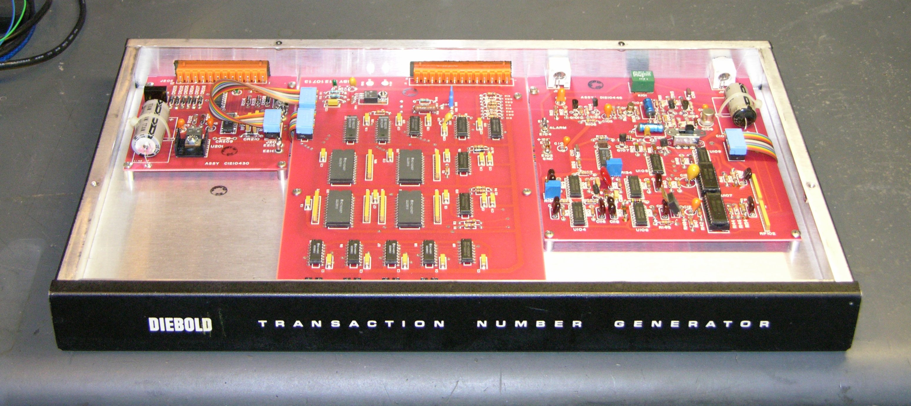
I’ve been swamped at work lately and it’s been spilling over to home, so I haven’t done much with CNC (or other projects) for several weeks. But I bought this Diebold Transaction Number Generator on eBay for $10, out of sheer curiosity to see what was inside. I have no idea what it’s supposed to do, and can’t find any information about it online, but industrial security and crypto equipment fascinates me.
My goal was not to reverse-engineer the whole thing, but to get a rough idea how it worked and look over the interesting bits. I think I’m not alone in that when I get a new electronic device, I like to look inside to see what they used to make it work.
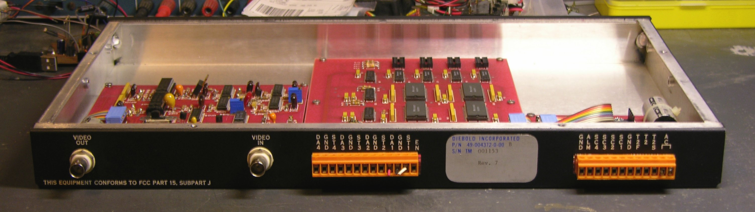
The back panel has video in, video out, and screw-clamp wire connectors:
(Nearly) all of my blog pictures are links to the full-resolution version, so you can click to zoom on this, but I’ll save you the trouble. Here are the labels over all the wire connectors:
| D A 4 |
G N D |
S T 4 |
D A 3 |
G N D |
S T 3 |
D A 2 |
G N D |
S T 2 |
D A 1 |
G N D |
S T 1 |
E N |
G N D |
A L M |
S C 4 |
S C 3 |
S C 2 |
S C 1 |
G N D |
T 2 F |
T 2 |
A C ⌈ ⌉ |
Okay, so I get what “AC” is, and “EN” might be enable, and “ALM” looks a lot like alarm, and there sure are a lot of ground lines, but the rest of the connections pretty much escape me. The DA-GND-ST triples make me think of some kind of balanced transmission, but wouldn’t a balanced transmission line have a shielded connector instead of a terminal strip?
And why video? Does this box generate transaction numbers and superimpose them on a video feed? I dunno. But it sure is pretty inside. Let’s have a look.

I really dig the red circuit boards (red solder mask). Green solder mask predominates these days, and I’ve seen blue and other colors, but I’m pretty partial to red.
The small board in the upper left appears to be mainly the power supply. The medium board in the upper right interfaces to the video feed, and the large board in the middle has some interesting digital logic on it.
Power Supply Board
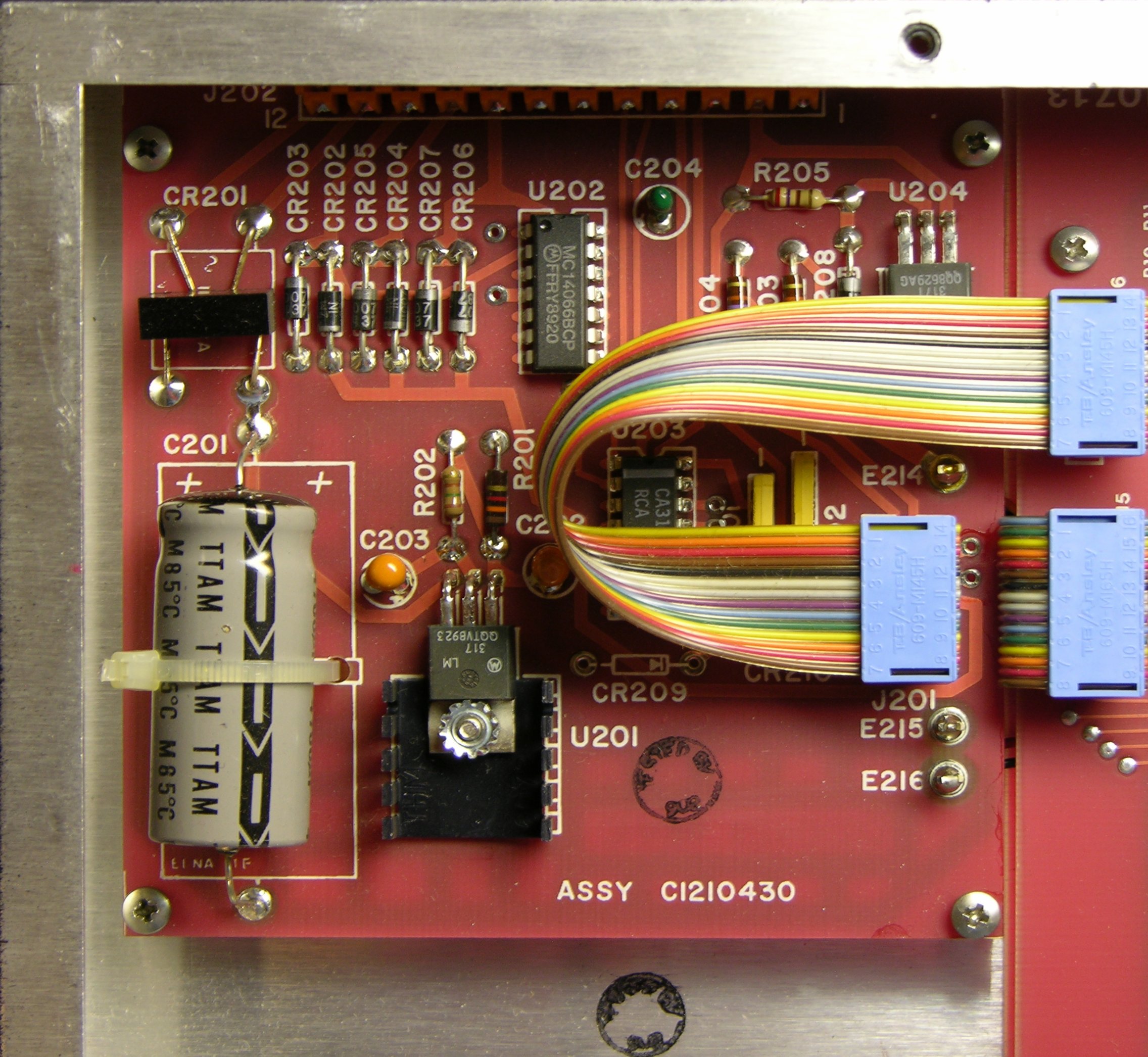
Here’s the power supply board. The bridge rectifier, CR201, connects to the main AC terminals on the back panel and feeds the LM317 regulator U201. U201 uses R202 (150Ω) and R201 (1.3kΩ) to set its regulated voltage.
The LM317 maintains a nominal 1.25V voltage across its reference terminals, across which R1 thus sets the reference current I1. The reference current also flows through R2, determining the regulated voltage. From the LM317 datasheet,
VOUT = VREF (1 + R2 / R1) + I1 R2
where
I1 = VREF / R1 = 1.25V / 150Ω ≈ 8.33mA
So
VOUT = 1.25V (1 + 1.3kΩ / 150Ω) + 8.33mA 1.3kΩ
≈ 1.25V * 1.87 + 10.8V ≈ 13.1V
With a bridge rectifier and capacitor-input filter, output voltage is approximately equal to peak input voltage, which is VAC / √2, so the box is expecting an AC supply voltage of not less than 18.6V; compensating for diode voltage drops gives about 20VAC. Knowing that, I could (if I cared enough) now power it up.
Note the bridge rectifier made of discrete diodes CR202-207 connected to external pins T2, T2F, and ground. CR206 and 207 double in two bridge circuits with CR202-203 and CR204-205, making me suspect that T2 and T2F are not meant to be used simultaneously, but as alternates. On the other hand, T2 heads off to the OUT1 (common) pin of the MC14066 quad analog mux chip. Kind of looks like it’s being switched to one of two different destinations.
Video Board
That’s about as much effort as I care to put into the power board, so let’s move on to the video board.
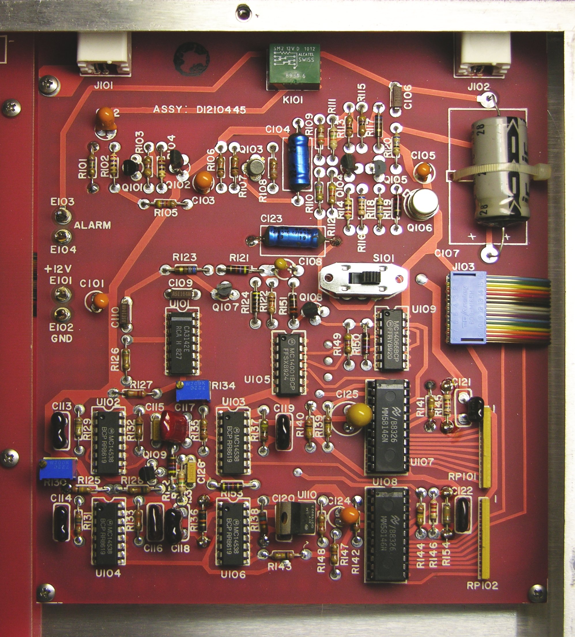
The four chips in the lower left are MC14538 oscillators, there’s another LM317 voltage regulator in the lower center, and the board has a mechanical relay up at the top. But the really interesting part is the two large chips in the lower right: MM58146 on-screen display drivers for television channel indicators. So this box is built to superimpose some kind of transaction numbers onto video. That’s interesting to know.
Logic Board
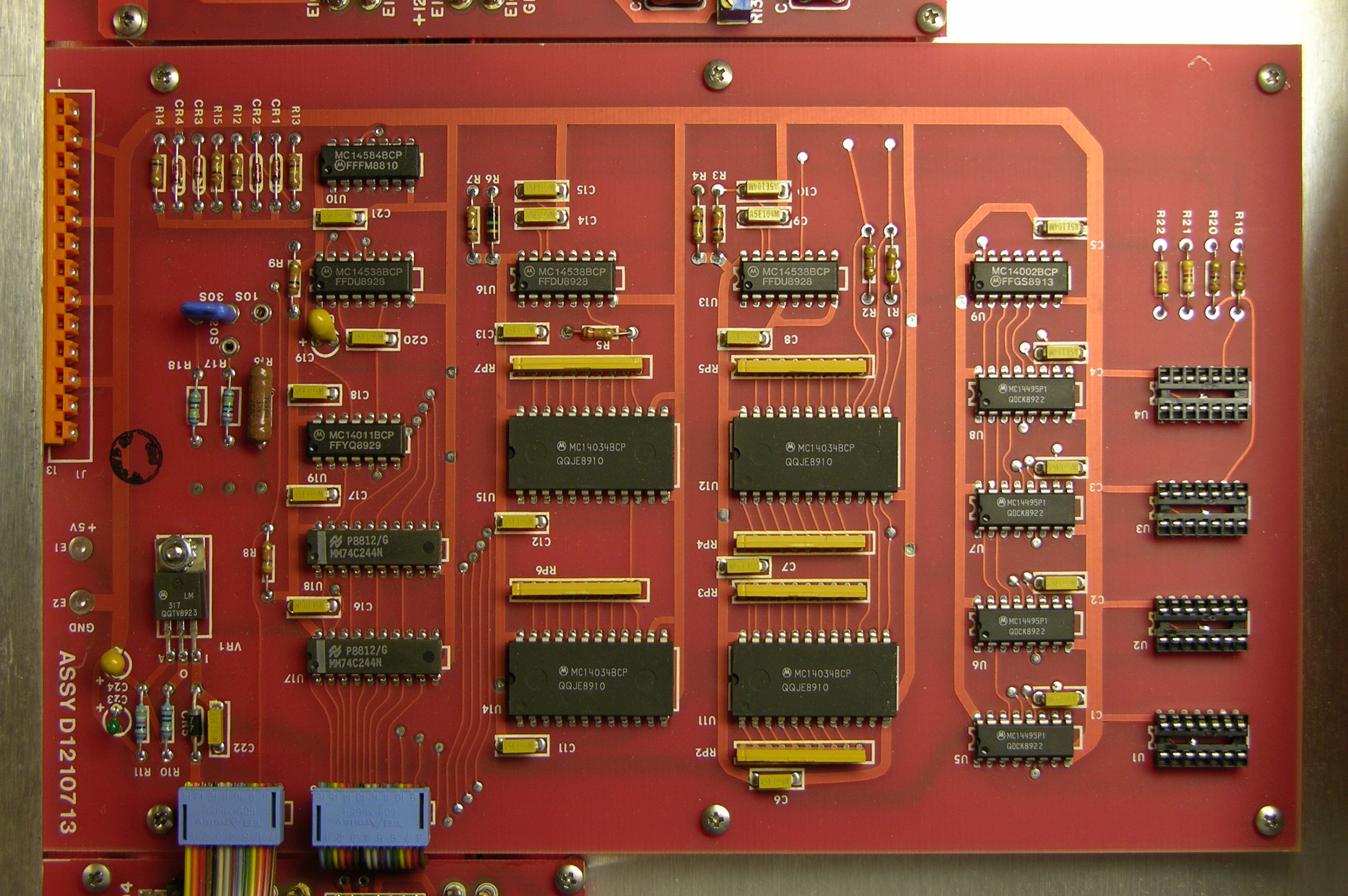
On to the logic board in the center, which I’ve rotated here to make the part numbers easier to read. The four chips U5-8 near the empty sockets on the right are MC14495 hex to seven-segment decoders. Whaaaa? I assume the on-screen display driver chips do their own character generation, so why decode binary to seven-segment? Maybe the four empty sockets U1-4 are for DIP seven-segment displays, to show the transaction numbers internally during testing or troubleshooting.
The four large chips in the middle, U11-12 and U14-15, are even more interesting. They’re MC14034 universal bus registers, permitting bidirectional transfer of data between two parallel buses, serial-to-parallel, and parallel-to-serial conversion.
The datasheet tantalizingly offers, “Other useful applications for this device include pseudo–random code generation,” but says nothing further about it. My guess is you’d wire them to shift and output bits, possibly with external inverters to shuffle things around at different stages, to make a hardware implementation of a PRNG algorithm.
You might even be able to wire them up to make a digital version of something like the rotors from a German Enigma cipher machine — but without spending a lot of time tracing pins on the bottom side of the board, I don’t know whether that’s how they’re being used here, or merely for more mundane purposes. It’s not quite worth it to me to figure out exactly how the MC14034s are used, so I’m pretty well done with my exploration.
Conclusions
I didn’t figure out a whole lot about the device, but it’s pretty clear that it takes a video input and superimposes numbers onto it. (One thing I wondered initially was whether it might be using video as a source of random noise to generate transaction numbers.) And it has some interesting bits inside, with logic chips I might be able to reuse for something else. That’s enough to satisfy my curiosity for now.
cool read!
comes in a cool enclosure too.
some point of sale video systems can hook up to the serial / parallel data from the register’s printer and then superimpose that over the video.
I emailed Mike to ask whether he could tell me more about it, and he wrote:
The device in Mike’s link overlays real cash register data (subtotals in different categories) onto the picture. I suspect that my Diebold isn’t that sophisticated, and instead just provides a transaction number (hey!) that correlates the register ticket with the appropriate spot on the security video.
Thanks, Mike!