The Theory
Sunday night, I read the MOSFET chapter in my semiconductor textbook several times, in preparation for beginning to build FET motor drive circuitry Monday. I took away these key points (some of which I already knew):
- Because MOSFET channels are very thin, their junctions are easily damaged by overvoltage conditions, not just overpower conditions. This is the reason for the standard cautions about static electricity and admonitions to store FETs in conductive bags or with foil wrapped around the leads, etc.–high voltage (even at a very low current) can destroy FET junctions.
- Because MOSFET gates are very high impedance, it doesn’t take much current to turn them on; thus it’s critical to tie the gates with a pull-up or pull-down resistor to keep them from floating and triggering wild dumps of power through the source/drain.
- MOSFETs like to have > 7V to saturate, i.e. turn completely on. If they’re not completely on, they’ll act as a resistive load and potentially dissipate a lot of power (equals heat, equals shortened lifespan).
- Read the datasheet carefully to determine which lead the heatsink tab is common with. On the ones I’m using, it’s the drain; so heatsinking to ground would short them out instantly.
The Circuit
I knew I wanted to design my bridge with complementary FETs (N-channel and P-channel), like I’ve done before with bipolars. There are designs available to do bridges with all N-channel FETs, but it takes extra work to bias up the upper FETs and their gate signals. It all seems very complex and nasty to me, especially when I have complementary FETs available: a large quantity of a couple of different MOSFETs, extracted from old printers’ stepper drivers. The IRF510 is a very common N-channel, capable of 5.6A; the IRF9532 is a P-channel that can do -10.0A.
Because the gate voltage should really exceed 7V to saturate the FETs, I didn’t want to feed the gate directly out of the LogoChip (or other TTL-like source). I have SN75452 peripheral drivers on hand, which buffer a TTL input into a high-voltage output. I’d looked at their datasheets before, scouring them over and over trying to find VCC2 (the high-voltage supply) on the pinout, to no avail. Finally I noticed that they have open-collector outputs (DUH), meaning the chips won’t source a high-voltage output, but they’ll sink an output that has a high voltage on a pull-up resistor.
Monday night, I started prototyping with a single IRF510 switching an LED on and off, to make sure I understood basic FET operation. I added an IRF9532 in a half-bridge configuration (the left half of the circuit below), and from their common drains wired one LED high and another low (with resistors, of course), then tested that the LEDs alternated as I applied a square wave to the gates. After demonstrating that the half-bridge worked correctly, I built the full bridge shown below, again testing with LEDs.
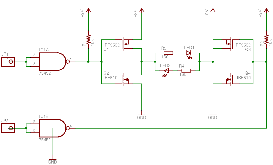
Note that the pin numbering on the 75452 is incorrect–EAGLE doesn’t have a definition for the 75452 and I haven’t made one yet, so I subbed a 7400-series chip with open-collector outputs. Now that I think about it, I probably have a 7400-series chip with high-voltage open-collector outputs that I could have used in the circuit instead. I’ll have to keep that in mind.
The Motion
None, of course. A single H-bridge is enough to drive a DC motor; but a stepper needs two, one for each coil. It was late enough, I quit for the evening knowing the bridge was driving LEDs okay, but without testing the motor.
Hello Keith,
I’m trying to build the H-bridge circuit that you have above and a little bit confused. For the SN75452 that you have below, which pin is connected to GND. I know it’s a dual peripheral driver with a total of 8 pins including the VCC and GND. So with the circuit above, if you use only one chip then all the pins would have been used since you have to power the circuit with VCC and GND. Thanks.
James.
James, the SN75452 has two two-input NAND gates with open-collector outputs, plus pin 4 to ground and pin 8 to VCC. Yes, the circuit uses an entire SN75452 per stepper coil (or DC motor).
You’d probably be happier with something like a 74*06 hex inverter with high-voltage open-collector outputs that could run as many as three coils from a single IC. Of course, you’d really be happier with something like an SN754410 or L293 or any of a host of other monolithic H-bridge drivers. The only reason I was experimenting with discrete circuitry was that I had the components on hand.
Thanks for the reply Keith. I have a 7406 that I can use. So according to the schematic above, you didn’t have to show the GND on IC1B of the 75452 since the VCC and GND of the 75452 will have to be connected anyway for the chip to be powered. Thanks.
James.