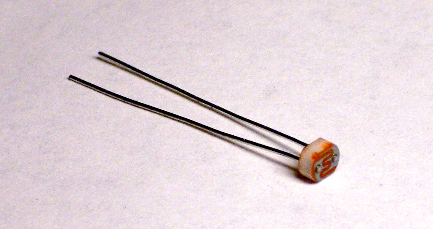
A cadmium sulfide (CdS) photocell is a passive component whose resistance decreases when light shines on it. CdS photocells can be used to detect when lights turn on, to orient things toward a light source (electronic sunflower), and to detect shadows passing across them.
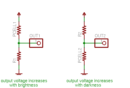
To use a CdS photocell, you put it in series with a resistor and put a voltage across them. This forms a voltage divider: the voltage at their junction is determined by the proportion of the two resistances. If you want brightness to increase the measured voltage, put the photocell on top; if you want darkness to increase the measured voltage, put the photocell on the bottom.
All that remains is to determine an appropriate value for the complementary resistor. Assuming you want output voltage to increase when brightness increases, the goal would be to make the output read as close to 0V as possible when it’s as dark as you expect it to be, and as close to your maximum voltage as possible when it’s as bright as you expect it to be.
To begin this calculation, I measured the resistance of the photocell (out of circuit) in light and dark conditions. With the photocell shown above, I found the following values:
| 450KΩ | in the dark (my finger pressed over it) |
| 36KΩ | in average light |
| 7.6KΩ | in bright light (under my fluorescent desk lamp) |
I discovered later that the photocell’s carrier PCB isn’t entirely opaque and a noticeable amount of light does leak in around the edges even when the face is covered. The resistance in true darkness would probably be even higher.
I decided to scale the photocell’s circuit to the range from darkness to normal room lighting, so calculating for a resistance range of 450KΩ to 36KΩ. Because this is only a single order of magnitude variation of resistance, I could already tell the voltage swing of the output wasn’t going to be as large as I’d like. I picked a 100KΩ resistor and estimated the voltage range:
5V * (100KΩ / (100KΩ + 450KΩ)) ≅ .91V
5V * (100KΩ / (100KΩ + 36KΩ)) ≅ 3.7V
So it has a swing of about 3V out of a 5V range. Not ideal, but it still provides a fair amount of resolution.
Finally, I connected the photocell to my LogoChip’s A0 input and confirmed its behavior by running print read-ad 0. I got a wide range of values out of the A/D converter, making this circuit quite usable for microcontroller interfacing.
I also posted a cookbook version of using the photocell on the TASD class wiki.
Don’t forget to factor temperature into the operating parameters. Cadmium Sulfide (CdS) is a semiconducting material, and most semiconducting materials have a current characteristic which may be quite sensitive to temperature.
Also, note that your finger is not necessarily opaque to infrared light, although this probably is of little concern to a CdS cell, since the spectral response is fairly poor in the infrared portion of the spectrum. That’s not necessarily the case for all photosensors. Silicon photosensors are quite sensitive in the infrared portion of the spectrum (unless they have an optical filter installed), and other photosensitive materials, such as Lead Sulfide, may be sensitive to even far infrared.
It’s possible to construct your own photosensor from a Silicon TO-3 cased transistor by carefully cutting the top-hat off. And, I have even seen plans for constructing your own photosensor from elemental Selenium.
Dave
Keith,
It looks like you know about electronics. I have a question for you. Before I ask my question, let me explain what I want to do first. I need a CdS photocell to build a device I learned how to make on a website. I would like to buy a quality photocell so, I think, the device will work better. Could you tell me where I can buy a quality photocell and how I can tell if it is a quality one. Thank you in advance.
Nick, I’ve never heard of different qualities of CdS photocells, and I can’t picture how that would make a device work better. Could you say more?
Keith, what I mean is that it can pick up weaker signals if it is more sesitive (meaning better quality) while a poor qulity photocell may not do the same. Thank you for your response.
Nick, sorry, I don’t have any experience with that. Off the top of my head, I’d try using a cell with a larger surface area, thinking that it might give you the same sensitivity but less noise, so you could amplify it further and get the effect of greater sensitivity. But I’d have to try it and see whether it really works that way.
hi. can you help me finding a way on how to design a circuit that detects the color of an object? i only need to identify 2 or 3 colors. our professor told us we’ll use an op-amp, LED (used as indicators when a color is identified) and LDR. thanks a lot.
Riel, why don’t you ask your professor for a hint? He or she will probably be happy to steer you in the direction he/she has in mind. And if not, then I don’t find it appropriate for me to solve the problem for you either.
Hello Keith. I am really interested in your article since I am a electronic student. I was working on a way to increase and decrease the speed of a motor with the light as an input. Just to make a bit more complicated I wanted it to have an inverted relationship. This means that as it gets darker the speed increases and vice versa. This is going to be my project for a simple electronic class. I just wanted to let you know about this in case a need some quick help or something. Thank you in advance.
Hi, Luis, thanks for dropping by!
So what class are you taking, and what are the requirements and components for your project?
Hey Keith, I am taking this class called Analog Electronics. It is a pretty interesting class, specially when I am as well taking Digital Electronics, in which I have another project to do later on. Not sure about the requirements you are asking for class? or project? We had bought a kit with parts which we have been playing with for a while now everyone got to do a project assigned individually. The one I explained you is mine. So far I have some sort of schematic which I just came up with. I am using CdS Photocell, a 555Timer, BJT and the 5V motor, plus other resistors and capacitor for the timer. the way I am going to make it work is to hook up the Cds where the ouput increases as it gets darker and vice versa. This output voltage is going to control the pin 5 (control voltage). this 555timer is set up in PWM in order to control the speed of the motor. Therefore the more voltage applied to pin 5 the higher the speed of the motor, since PWM setup increases duty cycle as pin 5 voltage increases. I am not sure if I can run the 5v 200mA motor just with the 555timer. If not I am planing to use the BJT to increase the current. What do you think about this. Does it make sense? I wish i could send you my schematic, but so far it seems to be ok in my head. I let you know how this goes. Thank you.
Okay so I found the first obstacle. I need to build my own pulse signal going to the trigger in the 555timer. I think I am going to use another 555timer. Unfortunately I cannot use a Function Generator from the lab.
Luis,
The 555 should not be used to drive the motor directly. Use the BJT as you mentioned.
As a hint… there is a way to do this with only 1 555 timer.
Hey i want to know how i would use this see im biulding a small robot and i want to make it work when light is shined on it so could you tell me?
Luis, I like your idea of using the photocell on the control voltage input. And as John notes above, you’ll definitely want to use the transistor to drive the motor.
Tanner, a photocell is not the same thing as a photovoltaic solar panel. A photocell changes its resistance in varying light; a photovoltaic panel converts light energy into electric energy, providing a voltage when light shines on it.
If you want your robot to be battery-powered and use light as a sort of activation switch, you can definitely do that with a photocell. There’s a nice example in the Jones and Flynn “Tutebot,” although I don’t know whether you can find information on that without buying their relatively expensive Mobile Robots book.
If you want your robot to be solar-powered, you’ll need photovoltaic panels, and you can find a ton of information by searching for BEAM robotics. Solarbotics sells kits for that, as well.
Hope that helps, and good luck with your project!
how would i be able to just use one 555, i need the astable one to create the pulse which is going to trigger the PWM one… is there another way to do this kuz i would be really interested in knowing? thanks
Luis,
There are a couple of ways to use just one 555.
I’ll provide another hint:
Use the 555 in astable mode where the output retriggers it. Put the variable resisor (photocell) in the section that controls the threshold and use the discharge output to control the output transistor (you’ll have to pull the discharge pin up through a resistor).
There is also a LM556 which has two 555s on the same chip.
Hi Keith
You may be able to get better dynamic range from your sensor by using a Wheatstone bridge. However, you’ll have to take a differential measurement, which makes the circuit a bit more complex.
I want to use a Cds for turning on a motor to move solar panel. What size do I need and how would I hook up for 12 volts.
Thank You
Ronnie
Ronnie, a CdS cell changes resistance depending on the amount of light received; it doesn’t produce a voltage. It would be possible to use the solar panel itself as both the brightness sensor and the power to run the motor, but that can get a bit tricky. It would be easier to use two CdS cells in a “photovore” configuration (you’ll find lots of example circuits online) controlling a separate power source for the motor.