I’m getting ready to collaborate with Cort on a project using ICs that aren’t available as DIPs; so I got some SOIC samples, and this weekend I hacked up some carrier boards to break them out to .6″-spacing DIP.
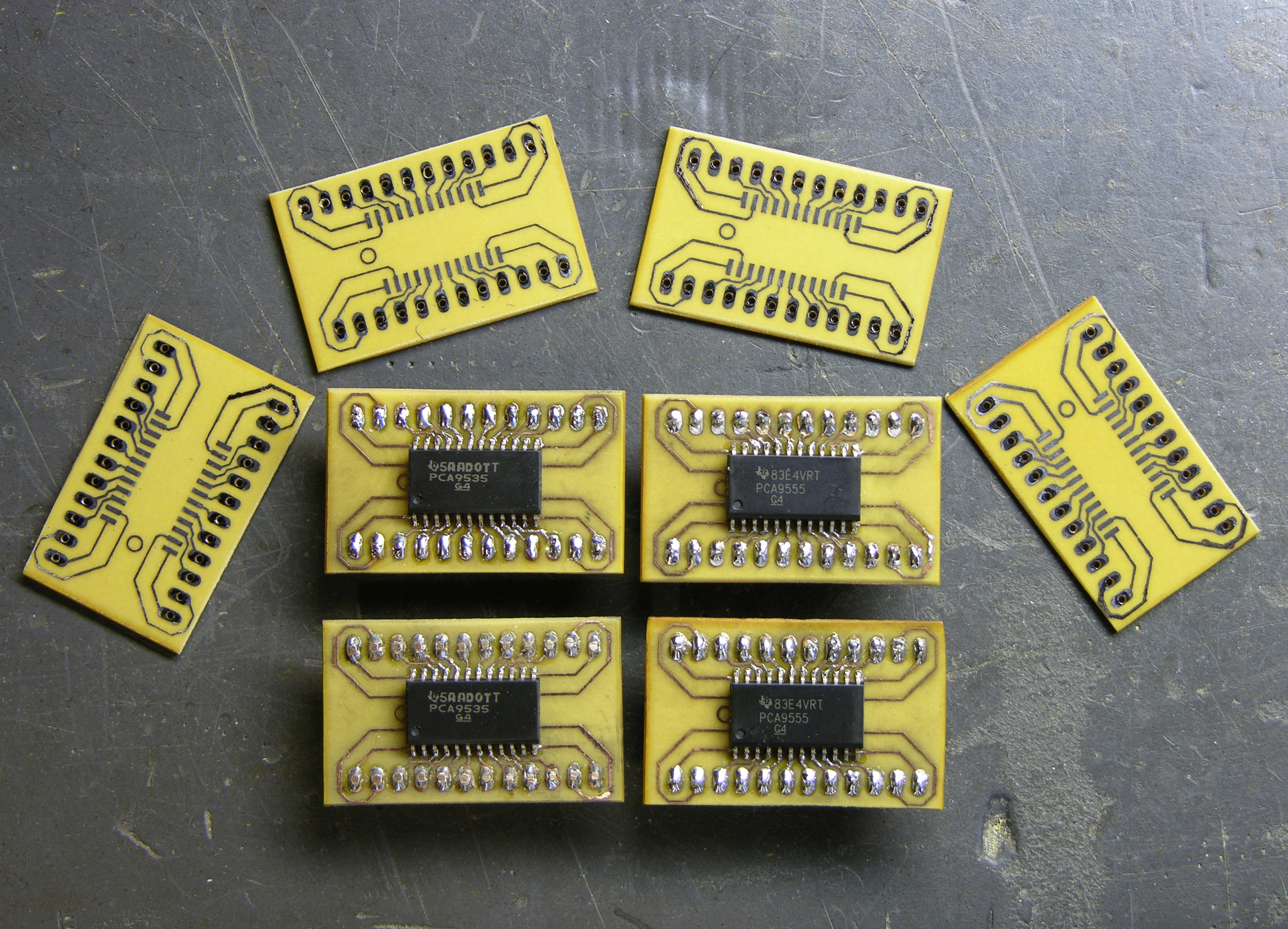
I made a few extras — as many as I could fit in my little etching tray — so I’ll be set for a while.
I also want to give the design away to anyone who wants it. It’s nothing special, but it might save someone else some time. So I’ve created a Free Circuits page where I’ll post things for free download under a  Creative Commons Attribution-Share Alike 3.0 Unported License. All the code I post here I do with the intent that it may be useful to someone else; but it’s nice to be explicit about it once in a while.
On to the Board . . .
I laid out the board, then panelized it as large as I could fit within free EAGLE, which turned out to be four wide by two high.
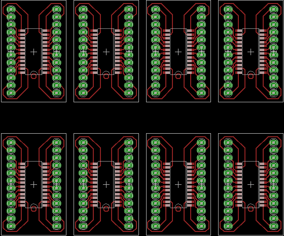
Here I’ve corrected it to put space between adjacent boards; but I didn’t think of that until after I’d etched mine, which made for some tricky separating.
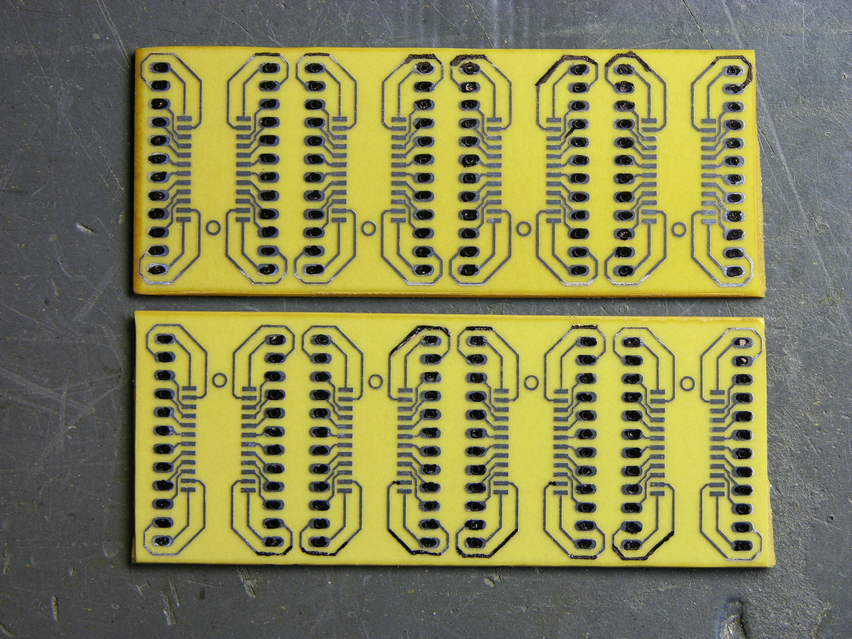
I did my usual toner transfer with the household iron, then used a Staedtler super-fine pen to touch up some spotty areas along the edges. The boards came out really well, in spite of using fairly tight spacing (12-mil traces with 9-mil separation by the middle pins). I inspected all the traces with a photographer’s loupe to be sure they had continuity where they should and separation where they shouldn’t.

Having stupidly left the individual boards touching each other on the layout, I wasn’t quite sure how I was going to get them apart cleanly. But I tried a new method, clamping them in my bench vise and using the jaw’s smooth edge as a guide to score front and back with the corner of my best $3 chisel. You can just barely see the score line above.
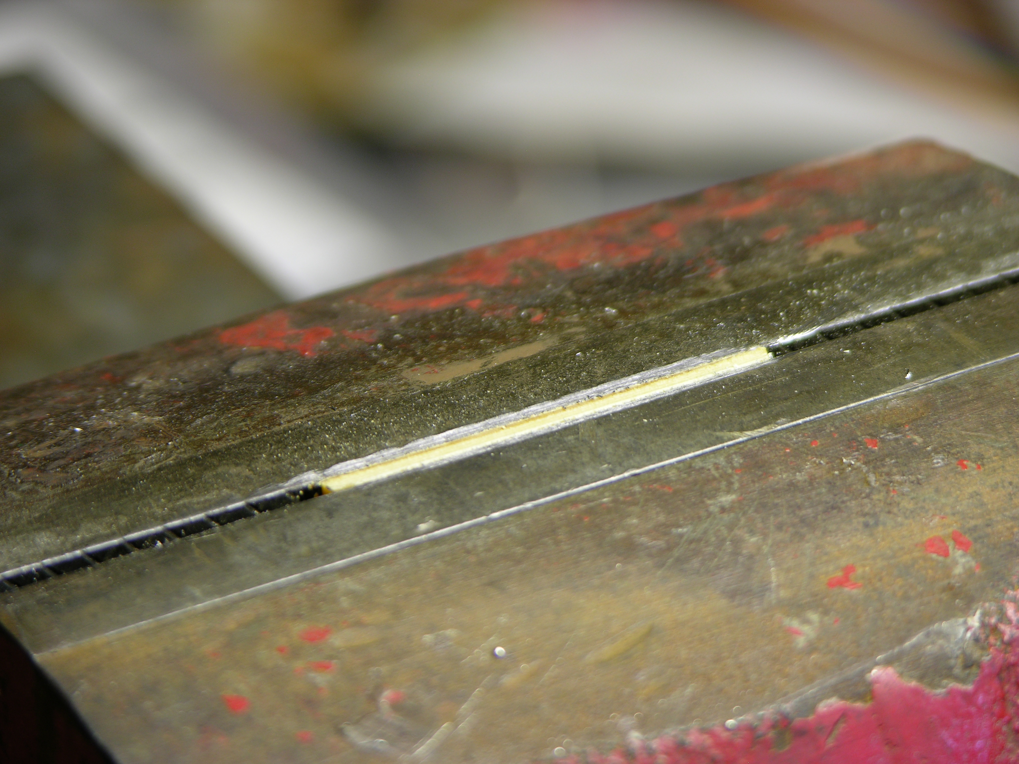
The boards snapped off clean as could be! I’ll definitely be using this method more in the future, even on boards I haven’t screwed up.
You have one of the best electronics blogs i’ve found. Great pics and interesting info…
Can you post instructions on how you did the panelization in Eagle?
TK, everything tricky I’ve learned to do in EAGLE is posted on my EAGLE tips and tricks page. Scroll about halfway down and there’s a link to where I learned about panelizing, plus my summary of how I do it.
Any chance you could share the eagle file (for at least a single board?)
Syd, yes, they’re linked from the article.
I did a similar SOIC breakout, though not as neat as yours.
http://www.elisanet.fi/entropia/picdump/vs1001k.jpg
Entropia, I like your pin labels!
What’s the wet-looking stuff on the board? Is that flux, or did you coat the finished board with something for protection?
Did you etch the board yourself? What method did you use for etch resist? It looks like you have very clean edges and good resolution — nicely done!
The wet-look stuff is indeed flux.
“I etched” the board at university (read: I looked as someone else did it for me), so I can’t really accurately comment on the process. The board was first printed on a regular laser printer and then exposed in a purpose-built PCB exposing machine. After that came the chemicals, I think it was the “regular” process. During the process the board stayed about 15 minutes in a blue chemical in a tank with an air pump in the bottom of it. Could that be the key to good edges?
At uni I usually tend to use the LPKF ProtoMat PCB router that’s also available. It’s a sweet machine that does 2-sided boards hassle-free and drills the holes too.
I design my PCBs in PADS Logic/Layout/Router since uni has licenses and (according to the profs) they use it in the industry too (I hope!).
It’s great!!!
I have some accelerometers with QFN (16) package, do you know if iexists these PCB for this kind of package ?
Thanks!!
Nacho
Nacho, I don’t know. But you should check out Sparkfun’s breakout board section.
Have you ever tried controlling a 8bit dac like a max517. I am all new to this unit and need to make something to control the 517 in about 8 different steps (from x00 to xff).
Nice work!