Cort and I are good friends and both interested in electronics, but have had surprisingly little opportunity to work on electronics together. He’s an amateur radio operator and very much into RF design, and I’m more interested in physical computing.
So when he started describing his receiver voter project and suggesting that I might be able to help out on some of the digital interfacing, I jumped at the opportunity. A radio repeater receives transmissions at one frequency and rebroadcasts them at a nearby frequency, effectively boosting the signal (by repeating it) without increasing transmission power over the legal limit.
The voter picks the best signal from several different receivers (possibly several miles apart, linked back to the repeater base) and routes it to the repeater. And Cort’s voter will have lots of pushbuttons, LEDs, and digital controls — more than he could wire directly to the Arduino he’s planning to use to control it.
That’s where I come in. Cort is very interested in learning the Arduino, but he hasn’t done much with microcontrollers lately and is to some extent playing catch-up with a decade’s worth of advances in technology. So I’ll pitch in and give him some ideas and programming assistance on the digital I/O.
I2C I/O Expansion
I started by looking for digital I/O expansion chips, and I did not start by looking for I2C. I’ve never worked with I2C before and I thought I’d find something with SPI, but oh no, that was not to be the case. Nearly everything I could find — and everything I could find that was readily available and affordable — used I2C. This is actually a good thing — I2C uses only two interface pins to talk to up to 127 devices, and SPI needs two pins for the bus plus a separate chip select line for each device — but it wasn’t what I was hoping for when I started looking.
So I ordered some samples, warmed up by trying to interface to an I2C EEPROM I had lying around (with no luck whatsoever, although I now know several things I did wrong and will go back to it soon), built some breakout boards, and got I2C communications up and running on the Arduino this weekend.
And the number of mistakes I made along the way was staggering. Not just little misunderstandings, but mind-numbing stupid mistake after stupid mistake, things I’ve know better since I was six. With a weekend like this, it’s a wonder I haven’t run over myself with my own car somehow.
So do what I say, not what I did.
Arduino I2C
First off, I had to get the Arduino talking to I2C. There’s not much online about doing I2C on the Arduino, and the most useful for me was Julian Bleecker’s blog post prosaically entitled Arduino and the Two-Wire Interface (TWI/I2C) Including A Short Didactic Parenthetical On Making TWI Work On An Arduino Mini.
It turns out there’s a Wiring library called Wire (why not, oh, say, I2C???) that operates the ATmega’s hardware I2C port and which has been incorporated into the Arduino software since version 6, so everything I needed was right there; I just had to figure out how to hook it together.
Between the Wire documentation being sketchy and not explaining how each function corresponds to an I2C function, its code examples being outdated and occasionally incorrect, my lack of familiarity with I2C in general, my not yet having a working I2C circuit to reference, and of course my many, many mistakes, this made for a bit of a vexing experience.
Let’s do it.
Give up analog pins 4 and 5
Analog pin 4 doubles as the I2C SDA (serial data) pin, and analog 5 doubles as SCL (serial clock), so you don’t get to use them any more. I like to put a comment at the top of my code to remind myself which pins I’m using and what they should be wired to, so:
/******************************************************************************
 *  i2c_gpio
 *  Keith Neufeld
 *  May 26, 2008
 *
 *  Prototype I2C interface to TI 9535 and 9555 GPIO expanders.
 *
 *  Arduino analog input 5 - I2C SCL
 *  Arduino analog input 4 - I2C SDA
 *
 ******************************************************************************/
Pull the Wire library into your project
#include <Wire.h>
This gets you declarations for the functions you’re going to be using, and magically tells the linker to look in the Wire library for functions you’ve referenced.
Set your I2C device address(es)
I’m an old C programmer, so I like to #define constants at the top of my program rather than hard-code them where they’re used. And the parens around each definition protect it from order-of-operation errors, since #defines are substituted lexicographically by the preprocessor, with no intelligence whatsoever about your intentions. (If this doesn’t make sense, don’t worry about it and just remember to put parentheses around numerical and variable #define substitutions.)
//  I2C device address is 0 1 0 0   A2 A1 A0
#define DIP_ADDRESS (0x4 << 3 | 0x0)
#define LED_ADDRESS (0x4 << 3 | 0x7)
[Update 03-Jun: The WordPress HTML monster ate my operators! Corrected DIP_ADDRESS and LED_ADDRESS to both be
<< 3 . Thanks, Kenneth!]
An I2C device address is seven bits. The I2C section of your datasheet will talk about the eight-bit address byte including the data direction bit (R/W), but this is a trick. ("Get an axe.") The Wire library will take care of the data direction bit for you automatically on each operation you perform, so you need to give it only a seven-bit address.
In my prototype, I'm using two different chips with the first four device address bits "burned in" at 0100 and the last three bits controlled by address pins on the chip, so you can use eight of these on one bus. I have one with all the address pins tied to ground (000) and another with all the address pins tied high (111), and I'm "OR"ing together the burned-in fixed bits and the values that I have the variable bits set to.
First mistake: Make sure you know how to convert from binary to hex (or decimal). It turns out that binary 0100 isn't hex 0x8, and it also turns out that the chips don't respond to an address that isn't their own. Seventeenth mistake: Make sure you remember how many hardware address lines you have. It turns out that binary 111 isn't hex 0x3, and it also turns out that chips don't respond to an address that isn't their own.
Sigh.
Initialize the Wire library
void setup() {
  // ...
  Wire.begin();
  // ...
}
Wire.begin() initializes the Wire library as an I2C master and reconfigures analog pins 4 and 5 as I2C pins. Wire.begin(address) (not used here) initializes the Wire library with the Arduino functioning as a slave at address address, useful if you want to use the Arduino as an I/O expander for another Arduino, build a BlinkM, or something like that.
Do some I2C output
From here on out, everything is specific to the device you're trying to control. Since I went 'round and 'round (what comes around goes around, I'll tell you why) on this before I got it working, and you probably won't be using exactly the same chips I am, I want to go through the datasheet and talk about how to translate the timing diagrams (correctly) into Wire code. And I'm going to cover writing to the device first, because curiously that's easier than reading.
One thing that's important to keep in mind throughout is which level we're discussing at any given time. Transmitting on the I2C bus is not the same as writing to a bus device's registers, which is not the same as causing a device to output on a pin. Unfortunately, all of these are called "write" by different documents in different contexts.
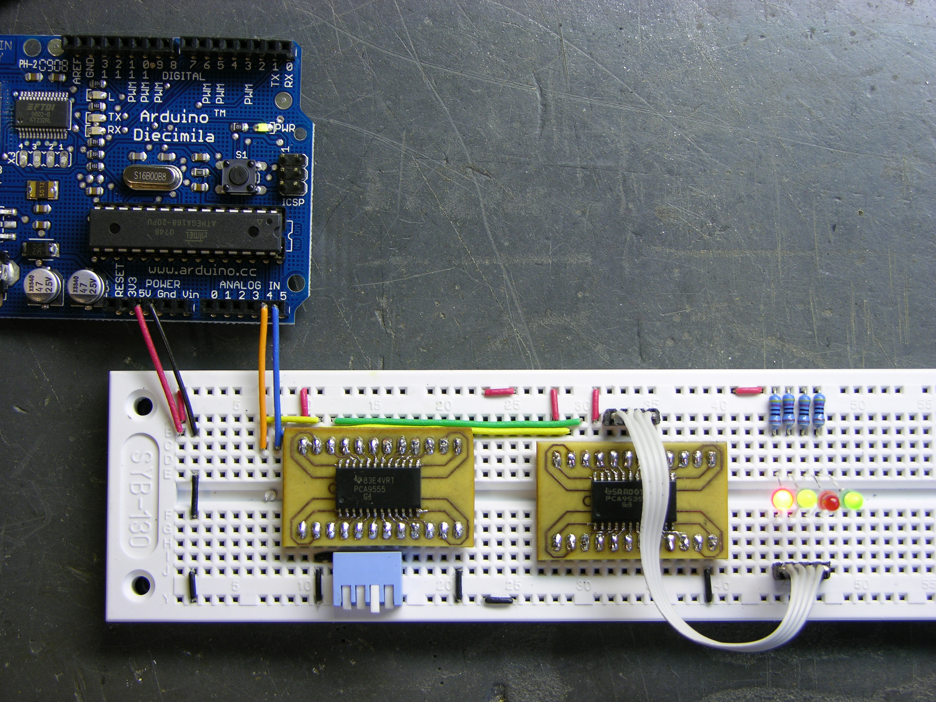
My samples that arrived first are Texas Instruments PCA9535 and PCA9555 16-bit I/O port expanders, so that's what I'm using. These chips give you sixteen additional digital I/O lines; you just supply power, three configurable address lines, and I2C. The chips are identical except that the 9555 has internal pull-up resistors, so I'm using the 9555 for inputs and the 9535 for outputs (where the pull-up is unnecessary and would add to the power draw when outputs are low).
The chips have eight one-byte registers, divided into four pairs for the sixteen bits' worth of input, output, polarity inversion, and data direction. To output data on the chip's pins, configure the pins as outputs by writing 0s into the data direction registers (they default to inputs), then write data to the output registers. To write to a register, send the chip the register address followed by the desired data. A write to one byte of a two-byte register pair toggles the register address to the other byte of the pair, so we can write both registers of a pair consecutively (in either order) without retransmitting the register address in between.
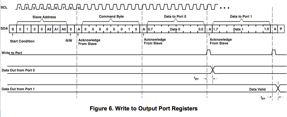
Working through the timing diagram one section at a time (open in another window if you want a bigger version to follow along), the slave address including the R/W bit is sent automatically by the Wire library when you call Wire.beginTransmission(address) . "Acknowledge from Slave" happens under the covers. The command byte is the address of the desired register, in this case 6 for the data direction register, which is transmitted by calling Wire.send(data) ; and again, the acknowledge happens automatically. Data to ports 0 and 1 is transmitted by calling Wire.send(data) for each byte desired. Finally, the transmission is terminated by calling Wired.endTransmission() .
Here's how it looks all put together in my code:
#define REGISTER_CONFIG (6)

void gpio_dir(int address, int dir) {
  //  Send config register address
  Wire.beginTransmission(address);
  Wire.send(REGISTER_CONFIG);

  //  Connect to device and send two bytes
  Wire.send(0xff & dir);  //  low byte
  Wire.send(dir >> 8);    //  high byte

  Wire.endTransmission();
}
Note that I'm sending the low byte first, then the high byte. I could just as well select the high byte of the configuration register (address 7) and transmit the high byte first, then the low byte, since the register address always toggles to the other byte of the current register. (It doesn't advance to the next register address as it does in some other types of chips.)
Having set the pins as outputs by calling gpio_dir(address, 0x0000), I can then output data on the pins with a gpio_write() function:
#define REGISTER_OUTPUT (2)

void gpio_write(int address, int data) {
  //  Send output register address
  Wire.beginTransmission(address);
  Wire.send(REGISTER_OUTPUT);

  //  Connect to device and send two bytes
  Wire.send(0xff & data);  //  low byte
  Wire.send(data >> 8);    //  high byte

  Wire.endTransmission();
}
Note that as these two functions are identical except for the target register address, they should really be abstracted into a gpio_register_write() function and two calls to the new function. For today, I just wanted to get a prototype up and running; for later, I'll build this into a proper object-oriented library that lets you create GPIO objects and call pinMode(), digitalRead(), and digitalWrite() on them like on the Arduino's native I/O pins (as well as still reading/writing them in bulk like I've done so far).
Do some I2C input
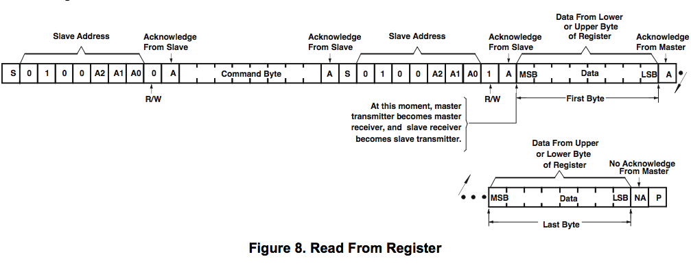
Assembly is the reverse of disassembly, right? Well, no. In order to read an input, you have to select the input register; and you select the input register by transmitting its register address.
So here's where I made mistakes five through sixteen; masked, of course, by the fact that I was transmitting to the wrong device address most of the time.
The first part is the same: send a device address by doing Wire.beginTransmission(address), and a register address (command byte) by doing Wire.send(data) . Then notice the "S" in there? That's another I2C start, i.e. Wire.beginTransmission(address) , and you have to do a Wire.endTransmission() first. (I tested lots of combinations before getting this right . . . and ultimately what I think I remember as my first hunch was correct, had I only been using the right device address at the time.)
Now send the device address again with another Wire.beginTransmission(address) , after which everything else is new. Instead of writing, we need to read; and the way to do that is Wire.requestFrom(address, numbytes) . (For the curious, as I understand it, the I2C master keeps clocking even during a read and the slave only manipulates the SDA line; so the master controls the number of bytes in the transfer and does need to know how many bytes are expected.)
Wire.receive() delivers the byte read from the wire, but the Wire library and the example code all show using if (Wire.available()) to check whether a byte was actually delivered before reading it. From my experimentation, I don't think this is actually implemented (or implemented correctly), and it's not like I can throw an exception if there's nothing there to read, but I'll go ahead and use it. (Laddie good boy!)
And here's mistake number somethin'-or-other (and the most embarassing one): Make sure that you actually return that value as the result of your function. If you just fall off the end of the function, you always get 0 back. Arrrrrgh.
All together now:
#define REGISTER_INPUT (0)

int gpio_read(int address) {
  int data = 0;

  //  Send input register address
  Wire.beginTransmission(address);
  Wire.send(REGISTER_INPUT);
  Wire.endTransmission();

  //  Connect to device and request two bytes
  Wire.beginTransmission(address);
  Wire.requestFrom(address, 2);

  if (Wire.available()) {
    data = Wire.receive();
  }
  if (Wire.available()) {
    data |= Wire.receive() << 8;
  }

  Wire.endTransmission();

  return data;
}
I/O Expansion in Action
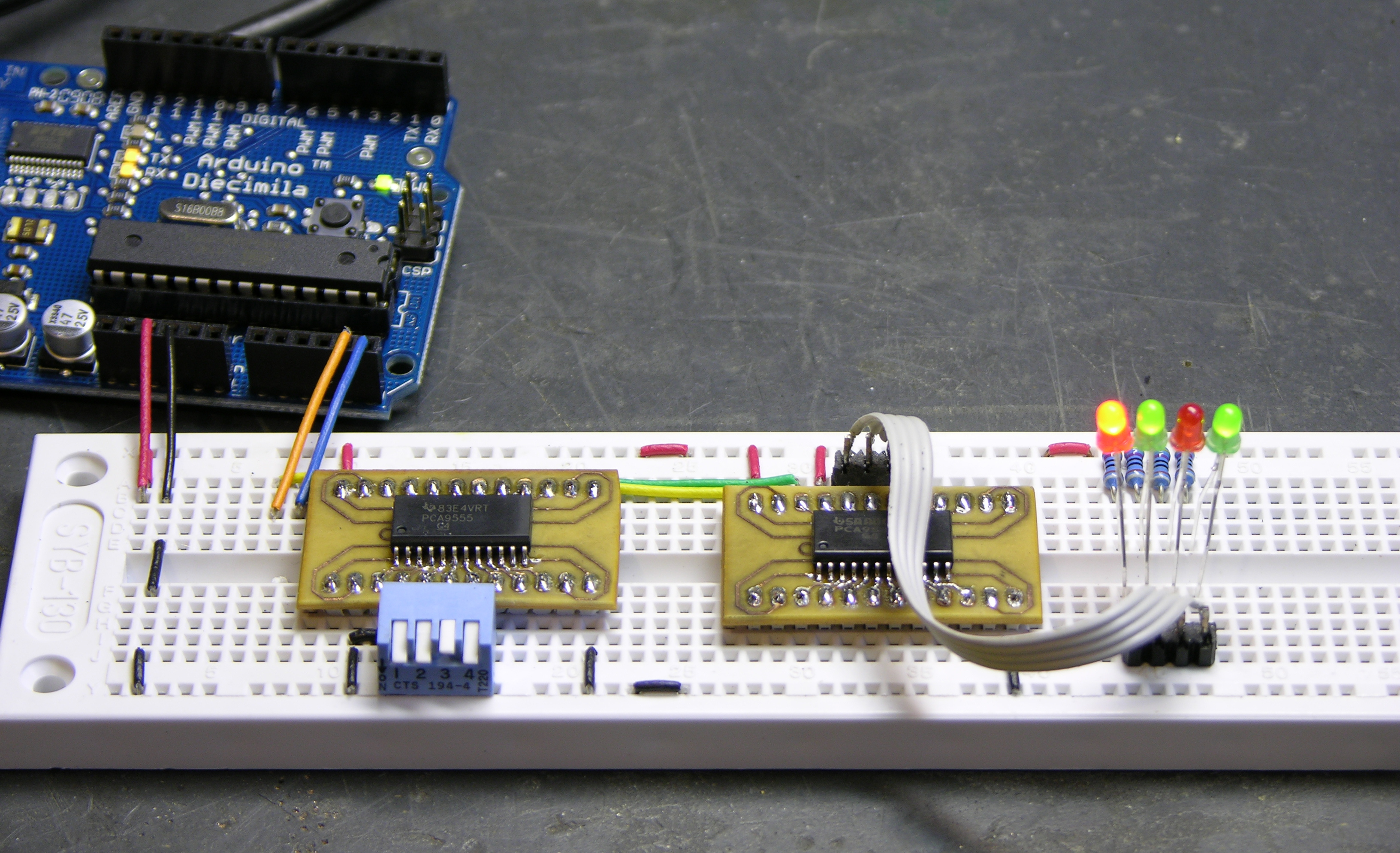
And thar she be. I'm reading a PCA9555 (has internal pull-ups) on the left with a DIP switch on port 0 pins 0-3 (left to right) and writing a PCA9535 (no pull-ups) on the right with LEDs on port 1 pins 4-7 (right to left). I deliberately put the LEDs on different pins of a different port in a different order to make sure I was successfully exercising every portion of the device. Flip the switches and turn the LEDs on and off, woo hoo, we're havin' some fun now!
All the Code
Here's the whole program: i2c_gpio.pde
I'll post a better version when I get it converted to a proper library.
Kozmik, I’m having the same trouble using Wire. Unfortunately, it’s giving me the same results with a MLX90614. I used an oscilloscope to look at the signals, and something is definitely not right. It looks like the master is pulling on SDA at a time when the slave should be acknowledging.
Keith, I have to echo what Simon says much earlier. beginTransmission just sets up the transmit buffer. endTransmission is what actually writes out the buffer, so in your code, it’s just doing an empty write after all the reading has occurred.
Re: http://www.neufeld.newton.ks.us/electronics/?p=241&cpage=1#comment-21778
You say that it’s lucky it works with a Stop/Start instead of a Restart like you wanted, but its by design.
First, you have already set up the register pointer. And second, you are in a Single-Master i2c bus. The entire point of Restart is really to keep control of a i2c session, so no other master will try to assert control of the bus. So you could setup the pointer on Slave X, Stop, work with Slave Y for a while, and then immediately read from Slave X without resetting the pointer.
The restart is just a way for a i2c master, in a possibly uncontrolled multi-master bus, to ensure the pointed register (or output data) does not change between write/reads.
Since it’s just your arduino and your designed i2c bus of two port expanders, restart is pointless.
Thanks for this great post. It helped me pass integers between 3 arduinos. Now I am trying to pass an array and experiencing trouble. I am using a multimaster configuration. I think I have narrowed down the issue to be on the receiving end.
void receiveEvent(int howMany){
while (Wire.available() > 0){
thisArray[6] = Wire.receive();
the above gets me the 6th value of the 1×6 thisArray. But I want to receive all 6 values.
thisArray[] = Wire.receive();
the above gives me an error message.
any advice would be greatly appreciated!
Psharma, it looks like you already got the
for()loop figured out on your own before I had a chance to get back to you. Glad you got that working!I’m trrying to pass integers between two arduinos
in the master I send the value:
Wire.beginTransmission(4);
Wire.send(myval );
Wire.endTransmission();
In the slave read the value:
while(Wire.available()) // loop through all but the last
{
tpo = Wire.receive();
}
And in the void loop print tpo
Serial.println(tpo);
But it prints 0.
so, what should i do to receive corrrectly the value?
Regards
bravo. i will def use this. saved me a headache.
I am reading through the Wire library files. can you tell me how to write a code, to scan devices on the I2C bus, without using the help of the Arduino Library?
very nice! Is there any way to get more than 8 on this bus? Perhaps another chip with a different “burned in” address? Any ideas?
it is very easy to expand to more than 8
one way :
http://www.maxim-ic.com/app-notes/index.mvp/id/955
or use MAX6956 (16 slaves and 20 GPIO per component)
Thanks!!! I love people sharing their trials with others. I just happened to buy this same 9555N chip and figured it would take me a while to get it working. I got it running in just a few hours thanks to this blog. Two silly things I spent time on:
1. I forgot that reading the inputs would show 0 for pressed instead of 1. I was ANDing with 0×01 to see if a bit was pressed. Duh.
2. I was using INT line to trigger interrupt on arduino with attachInterrupt() and was wondering why I always got an interrupt on the key release too. It’s because INT is reset when you read out the input bytes, and it goes low again any time an input changes, even if back to 1.
Ive run into a nasty problem…. I2C aparently is having some serious issues. Periodically my uno freezes. I can reproduce it just by shorting the scl and sda (which i did accidentally at first). I am using the proper pull up resistors and such with my pca9535′s … My uno just freezes. I’ve googled the issue and it seems that it may be a problem with the wire library (uh oh)… Ive based my code from the example here. Anyone have any thoughts to share or suggestions here?
Thanx in advance!
What’s the issue with the wire library – I ahve some code I think should work to use I2C connection between an Arduino Mini Pro and an accelerometer but the Mini Pro seems not to want to pull SDA or SCL low; the pin works for other operations and the problem is repeatable on different Pro Minis…
Not sure… Did u try a higher resistance on your pull up?
hope you are fine….i amusing sharp infrared sensors to arduino and then send this dat to master NXT……
BUT I AM STRUGLING WITH CODING ANY ONE CAN HELP ME PLZZZZZZZZZZZZZZZZZ
Hi
I have run into problems with a compass and a Arduino im using it as rov controller and compass is 12C problem it freezes my arduino deuliomive ?
Ideas i have loaded libary etc but now joy ? soon as i remove compass the coms are up again it just seams to cut out arduino
Thnx
just make sure you are using around a 10k resistor to your +5 on each scl and sda. Aslo my problem got loads better when i lowered my resistor ohms (was using like 50k)
Sir,
I am a ham and want to control clock generator CY27ee16 for my SDR radio project using Arduino. Can you please guide me to communicate with this device using I2C.
Thanks in advance-vu2iia
hy keith,
i’ve a generall question, i’ve order this device:
http://www.dorji.com/pro/sensor-module/Compass_pressure_sensor.html
and i wonder now if a arduino can handle the command sequence
they put a example program for a pic u-processor online and im not quite sure
if i can handle this with the wire commands
as example – when i understand that minimalistic datasheet right, i’ve to wakup the device and im not quite sure if the timing of the “data read” is possible with the wire library
as example a code snipped how its programmend for the pic u-processor:
unsigned char IIC_ReadByte(void)
{
unsigned char ucValue;
unsigned char ucIndex;
ucValue = 0;
DATA_SET = DATA_INPUT;
SysDelay(DELAY100US);
for ( ucIndex = 0; ucIndex < 8; ucIndex++ )
{
ucValue <<= 1;
IIC_SCL_LOW();
SysDelay(DELAY100US);
IIC_SCL_HIGH();
SysDelay(DELAY100US);
if(DATA)
ucValue |= 1;
SysDelay(DELAY100US);
IIC_SCL_LOW();
SysDelay(DELAY100US);
}
return ucValue;
}
they predefinded #defines are trivial and realy mean mostly 0 or 1
are u used to the wire library and how its programmed so could you tell me if its possible in generall to use this device with arduino and his wire library or do i have to go deeper into that topic and programm my own "wire-library" ?
would be great if you could help me
thx
vance
Vance, I suspect you could use the Arduino’s Wire library, but I’d have to try it myself with this device to be sure. Give it a shot and come back and let us know whether you got it to work?
Dear Keith,
Thank you for a very interesting and helpful site.
I am trying to use Arduino to read temperature sensor DS620.
I am unable to get temperature data.
Hope you could give guidance in this or provide code for Arduino to read DS620 using Arduino wire library.
Thank you.
Ahmad.
Keith, could you please explain in a bit more detail what de parenthesis do in the #define declaration? I know that normally the preprocessor simply replaces the first string by the second string.
Further I have implemented a couple of I2C-functions to controll an absolute barometer, an ad-converter and a high side current/power monitor without using the wire-library. My functions use “bit-banging”. This way you have more controll and smaller code. Probably at the expense of speed, but with most I2C-projects speed is not of the utmost importancy.
Thanks in advance, Pim.
Waaaay back when I learned C, I was taught to put defensive parentheses around macro arguments, as macros are expanded syntactically by the preprocessor, not semantically by the compiler.
By way of example:
#define mult(X,Y) X * Y...
a = mult(b+5, c+3);
expands into
a = b+5 * c+3;which is (with a change in whitespace to show order of operations)
a = b + 5*c + 3;which is unlikely to be what was intended. So I always parenthesize macro arguments in
#defines.Actually it is DS1620 not DS620, and the DS1620 uses a non-standard two wire communications method with a clock added that is similar to SPI so you’re not going to be able to use I2C methods with it.
Oh and their temp sensors are One-Wire devices, the DS1820 for example who are supported directly on the Arduino, after a fashion.
To Ahmad and Greg: As the Dallas-Maxim DS1620, the DS620 is also a Digital Thermometer and Thermostat. The DS620 communicates via a 2-wire bus with a protocol that looks identical to I2C. The DS1620 communicates via a 3-wire bus which is not compatibel with I2C nor SPI, but can easily be handled by ‘bit-banging’.
Correct. I just found the part number in their database for data sheets. Looks interesting but using it isn’t possible. I’m largely a through hole builder. I’ve used SMT stuff sparingly…
And about the unique DS1620 it is indeed like that. I recall using one with the BASIC Stamp.
The DS620 doesn’t use the I2C standard of course. It uses something completely different. Naturally the website does describe how the protocol methods and the ways to make it work.
hi i have one question.
how to write a data continuously for i2c,in arduino uno :
here my code: this code is interfacing a dac to arduino using i2c protocol
#include
#include
#define disk1 0xc0>>1 //Address of 24aa32a eeprom chip
//#define sda A4
//#define scl A5
char incomingByte;
unsigned int integerValue=4000;
void writeEEPROM(int deviceaddress, unsigned int eeaddress,unsigned int data )
{
Wire.beginTransmission(deviceaddress);
Wire.write((int)(eeaddress >> 8)); // MSB
Wire.write((int)(eeaddress & 0xFF)); // LSB
Wire.write((int)(data >> 8)); // MSB
Wire.write((int)(data & 0xFF));
Wire.endTransmission();
}
void setup(void)
{
unsigned int address = 0;
Serial.begin(9600);
Wire.begin();
}
void loop(){
unsigned int address = 0;
if (Serial.available()) {
integerValue = 0;
while(1) {
incomingByte = Serial.read(); // char
if (incomingByte == ‘\ ‘) break;
if (incomingByte == -1) continue;
integerValue *= 10; // shift left 1 decimal place
// convert ASCII to integer, add, and shift left 1 decimal place
integerValue = ((incomingByte – 48) + integerValue);
}
}
Serial.println(integerValue); // Do something with the value
delay(500);
writeEEPROM(disk1, address, integerValue);
}
OUTPUT: DIGITAL VAL=4000, MY VOLT =4.8V THE I2C IS WORKING FOLLOWING MANOR: S C0 A 00 A 00 A F0 A 11 A P
THIS CODE IS USED TO DAC. THIS WORKING PREFECT IN ONE TIME. that means the data write once in dac the dac provide equal volt. and next time arduino send stop bit the communication stopped here.MY AIM THE DIGITAL VALUE IS PROVIDE BY USING SERIAL SO I NEED WRITE DATA CONTINUES PLEASE ANY ONE HELP ME.
I WILL TRY ANOTHER METHOD for repeated start BY REPLACING THE LINE IN ABOVE CODE, THIS SEND DATA CONTINUES BUT IN THE DAC do not produce OUTPUT VOLTAGE. THIS MY PROBLEM.
THE CHANGES IS :Wire.endTransmission(false);
the output is:S SR C0 A 00 A 00 A F0 A 11 A SR C0 A 00 A 00 A F0 A 11 A ……. TO FOLLOW THIS MANOR. PLEASE any one HELP ME AM WAIT U R REPLY THANK YOU