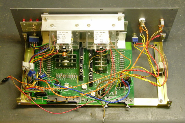
One of the electricians at work gave me a bunch of circuit boards from decommissioned equipment this week. It’s usually elevator stuff, so I hadn’t paid much attention to it other than to note the pretty colored wires.
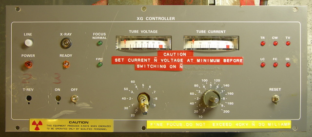
The I was taking it out of my trunk to put into a “process later” pile when I noticed the front.
“X-Ray.” 60kV tube voltage. “Fine focus.” Whaaaa???
Combined with the way all the front-panel switches and knobs are bent and broken off, I’m guessing this was in one of the laboratories, some unfortunate researcher accidentally stepped in front of the beam and mutated into a creature with superhuman strength, and in the resulting chaos demolished the equipment. Since it was destroyed, now I have it. Cool!
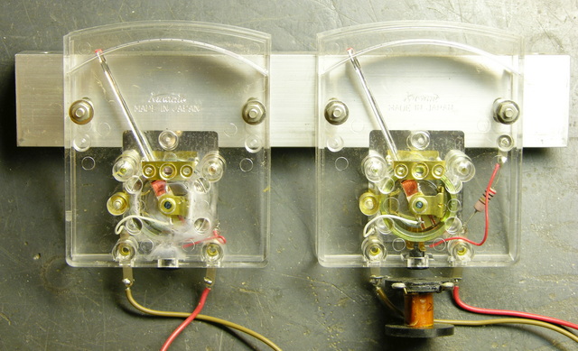
I went ahead and disassembled it tonight. Here’s a different view of the meters:
And there’s a big pile of connectors, resistors, and lovely wires on my workbench.
Cool Rotary Switches
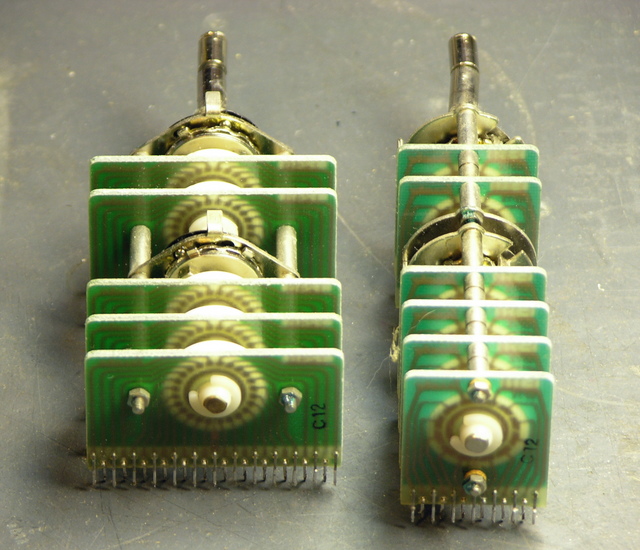
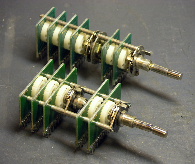
Here are the two rotary switch assemblies. Their knobs were broken off and their shafts bent, so they’re not working terribly well, but I’ve improved them a little.
They have circuit boards that are ganged together, with the inner shaft turning the back set of switches (of course) and the outer shaft turning the front set.
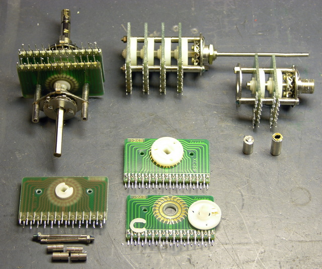
The mechanics of the assemblies are fairly intricate. You can click the picture (as always) for the full-resolution version if you want to follow along.
Clockwise from the bottom:
Every switch position is a separate trace on the PCBs, with 24 positions on the wide assembly, 12 positions on the rear part of the narrow assembly, and two sets of 5 positions on the front part of the narrow assembly. A wiper on the plastic rotor connects the PCB’s inner ring trace to each outer pad in turn.
In the upper left, you can see how the limits of rotation are set by two discs with tabs sticking out, which bolt onto the head end of the (sub-)shaft. The discs’ tabs stop against a rear-pointing tab on the head-end mounting plate, which is on the underside in this picture.
Shown at the top, the rear portion of the narrow assembly is still in good condition. It was pretty gummed up, but a few sprays of silicone lubricant got it turning nicely. The PCBs are mounted on a set of multiple threaded rods, threaded spacers, and unthreaded spacers. The rotor’s detent action is provided by the wavy disc on the back side of the mounting plate, a ball bearing sitting in a hole in the plate, and a leaf spring on the front side of the plate.
In the upper right, the front portion of the narrow assembly is okay, but the outer shaft that used to rotate it was sheared off at the base (shown immediately below it).
I had to saw the front knob off the narrow assembly’s shaft to get the assembly apart and make part of it usable. You can see that the kob appears to have been threaded onto the end of the shaft; but with a vise and a pliers, I was unable to turn it loose. The shaft had been pretty badly bent anyway, so I have no hard feelings about having to saw it off.
Idea for Rotary Switches
So I’ve actually been looking for rotary switches like this, and thinking of trying to make some myself. This unfortunately is not the form factor I need, but it shows the idea is sound.
The high school robotics team has strict rules they have to play by, and one of them is that the joysticks used to control the robots in non-autonomous mode must work like PC joysticks (I think the PIC that runs their control panel is charging and timing an RC circuit to determine the joystick position) and cannot have any supplemental power.
This wouldn’t matter, except that the linearity of the joysticks they have is poor; and with (apparently) only 8-bit sampling, there’s not as much they can do programmatically to correct the linearity as they’d like. So it takes a bit of programming effort to eliminate drift when the stick is physically centered; and then when they start to move the stick, the robot lurches into action with not much fine control over low speeds, and at high speeds is pretty much just maxed out.
Of course I assume if it were my robot, I could correct most of that in programming. ![]() Still, that’s a lot to ask of high-school kids who are already making amazing engineering accomplishments on a very tight timeline.
Still, that’s a lot to ask of high-school kids who are already making amazing engineering accomplishments on a very tight timeline.
So Ron (of the fundraising concert, and father of the team captain) would like to figure out how to build a new joystick that abides by the letter and spirit of the rules but gives finer control over low speeds and has really significant jumps up to maximum speed only when you floor it. Obviously he wants pots with an S curve response (log taper in both directions from center), and he hasn’t been able to find that commercially, at least not that he could retrofit into a joystick.
His idea was to do it discretely — come up with some sort of switching action, then connect that to a resistor ladder. He could play with the resistor ladder to his heart’s content until he got something that “felt” right for the application — make it pluggable and let the kids swap resistors until they got a response curve they liked. And he wasn’t too worried about the robot lurching as the joystick went from step to step on the ladder — he feels that relatively few values would suffice.
If these 24-position rotary switches could fit into a joystick’s gimbal assembly, they’d be fantastic for that! Reserve the middle 3-4 positions for a broad center band to eliminate home-position drift, then have ten more positions in each direction for different speeds.
Except I’m pretty sure the gimbal assembly has little 3/4″-diameter pots right there on it, and these big PCB things just wouldn’t work. Feh.
I thought about etching my own PCBs to replace the wafers inside a couple of sacrificial pots, but I hadn’t figured out quite how to route all the wires out.
Open to suggestions here.
Yuck! I can’t imagine using a multiposition switch for joystick applications. I’d think the wear rate, and contact noise problems would be severe. It might work, at least for a while, but I don’t think I’d want to design something long term using that.
The original IBM PC Games Control Adapter (GCA) used a variable resistance for each axis. The variable resistance was used to determine the period of oscillation of a 555 timer chip (I even have the schematics for the card somewhere; they were published in the Technical Reference.) (Ok, so it may have been the quad version of the 555; is that the 558?). If I remember correctly (and it has been about 25 years since I’ve looked at that thing), the 555/558 was wired as a monostable, and you started it off with a write to the GCA port, and then, the timer elements for each axis timed out as you were reading them in a loop.
Oh, one of the nice things about the IBM GCA card is that it had a prototype wirewrap area included on it, which could hold a couple of TTL circuits. It was pretty easy to toss a couple of latches on there, and use the address decoding on the card itself, to make an 8 bit output port.
One of the nice things about this technique (555 monostable timers) is that you can get as much precision as you want with such a system. It’s basically controlled by the software that reads the timing of the 555 chip (and the reference clock, of course).
Some applications included a joystick calibration routine that you could use to calibrate your joystick to reduce drift and define the limits. Another approach would be to use software to declare anything within so many units of the center as being “zero”, and then to scale the action based on a software defined slope from outside the zero range to the limit.
In any case, that should give you a LOT more resolution than trying to use switches, no matter how many positions the switch has, since any practical switch will be limited to well under 120 contacts on each size of zero (while, with the 555 monostable, and a sufficiently fast clock, you should be able to get many thousands of levels of resolution).
For the old timers here, some of us can remember some of the early joysticks, such as on the Atari games console of the 1970s. These weren’t proportional control, but were simply switch contacts for left/right/up/down. No matter how hard you pushed, the output was either on or off. Trust me when I say proportional control is much nicer.
As for the X-ray controller, I make it a habit of not messing with things that can make you glow in the dark. Of course, we all know that there’s not much danger from an x-ray system as long as it’s powered off (and the capacitors discharged). Still, it’s an interesting piece of equipment.
However, something is confusing me. Most x-ray systems don’t allow you to vary the tube voltage/current; most are fixed. This appears to be a rather specialized x-ray system. Ah, ok, here are some links:
http://www.csb.yale.edu/data_collec/yale/rigaku.html
http://www.mines.utah.edu/pyrite/xray/Rigakurun.html
This appears to have been the control panel for an x-ray diffraction instrument.
Dave
Dave, the supplied robot control system is presumed to use a similar RC timing circuit to read the joystick position.
As I noted, if I were doing the programming, I’d build in a dead band and correct the slope in software. (Already did, in fact.) But trust me when I say that those are some pretty fancy programming concepts for the kids.
It seems you are talking about BEST robotics. If so, you can’t add to whatever BEST gives. I’d love to figure out a way to add another remote to our robot. I had trouble with the drift as well.