I’ve been quiet lately because I’ve been too busy … hope to break free of that by mid-May and get back to some projects.
I’ve made time to do a little server work; I’m trying to build a more consistent set and get my servers all up to current OS versions. I have three nice rackmount server cases, and while scrounging ATX motherboards to put into them, I ran across this.
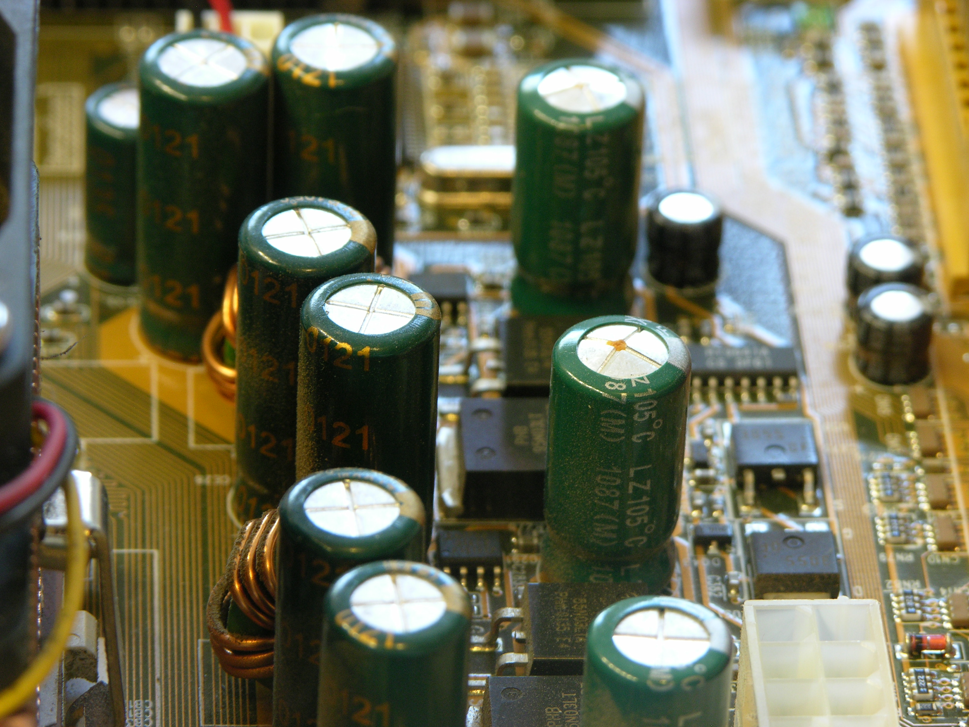
The electrolytic capacitor just to the right of the center of the image is seriously bulging, as is the out-of-focus capacitor behind it. They both test good with the Capacitor Wizard, but I wouldn’t trust either of them with power applied, at least not inside anything I care about. Always at least visually check electrolytics before you power up something that’s been off for a while.
Desoldering was easy — heat both leads and gently rock them out.
Cleaning the solder out of the through-holes was trickier. At least one of the holes was attached to one or more large copper planes and kept sucking away the heat — I had to add solder, keep it preheated with the iron so it stayed liquid through the hole’s whole depth, and quickly slip the solder braid into place. Heating solder braid on top of a topped-off through-hole wicked away the top solder before heating it all the way through.
And then I ran out of solder braid. Ended up drilling out the holes, which I’d wanted to avoid in order to avoid any risk of damaging the plating. But I picked a small enough bit that I didn’t even remove all the solder, and it worked out okay.
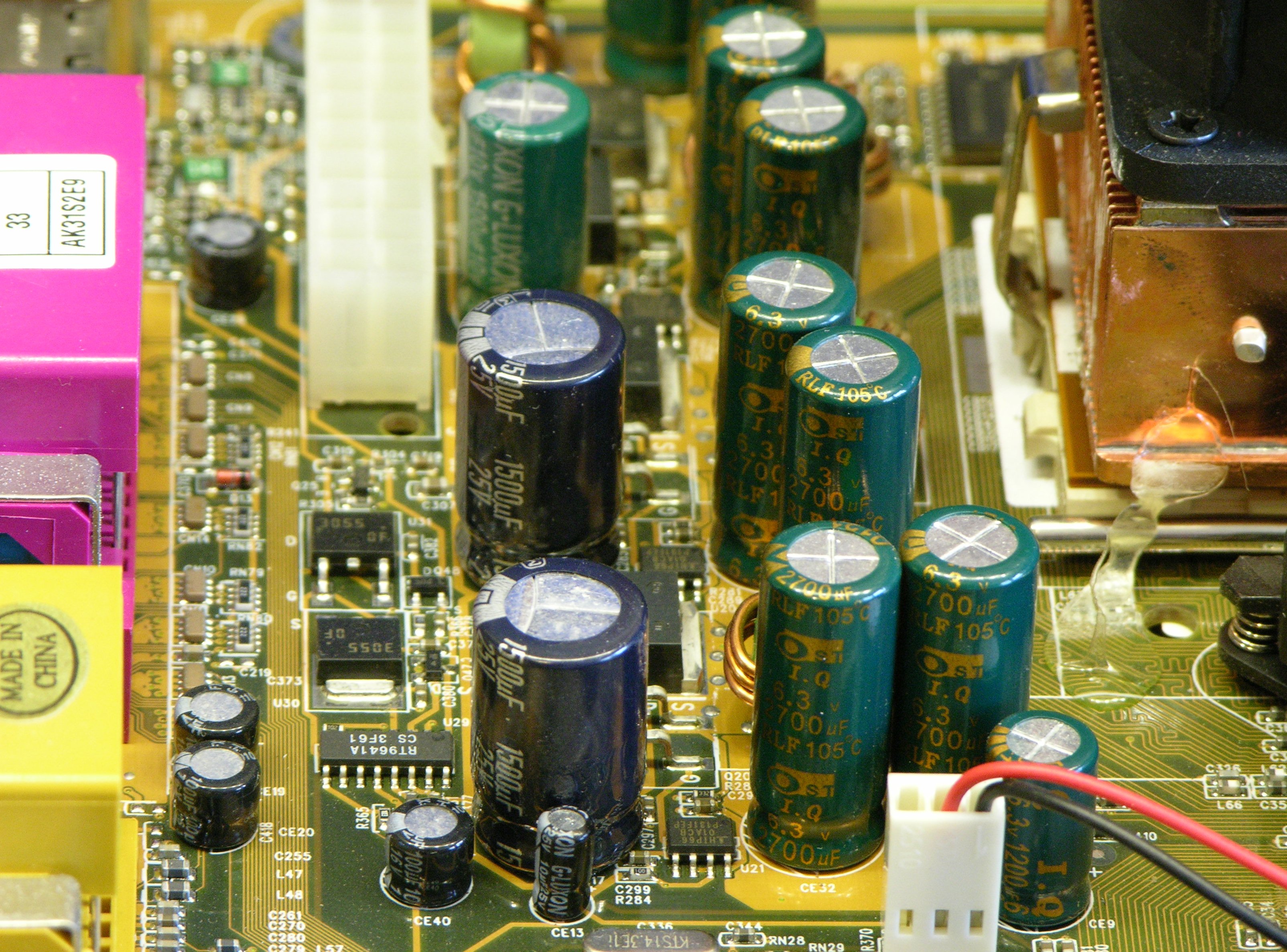
The replacement capacitors I had on hand were a little wider and crowd adjacent components, but at least are rated for 105°C like the originals. And they seem to work; the board is now cheerfully running my new backup server.
I did this a few years ago with a P4 board that had been seriously cooked in a poorly ventilated case.
My issue was a combination of difficulties working with RoHS compliant solder (I believe – but now you mention your copper plate issues, I’m not so sure) and densely packed capacitors.
I ended up solving the first by pouring a *lot* of heat into the area and applying my old-school solder to the area which seemed to make it easier to work with. The second problem I solved by using every last milimeter of the up-rated replacement caps’ leads to move them off the board and eventually hot-glued them on their sides a couple of cm away from their pads.
The board has been through a lot and is still running today =)
Nice work, I’ve done this a couple of times and it’s pretty satisfying to bring something back to life.
I used a solder sucker and had good results at clearing away the remaining solder (I had to add a little new solder to get things moving). Did you try a sucker after the braid? They’re normally pretty good at removing solder filling holes. I’m not really a fan of braid (except for SMD work).
More info on this (relatively enormous and ridiculously long-term) industry problem is here: http://en.wikipedia.org/wiki/Capacitor_plague
Whenever I do a cap replacement, I don’t stop at the failed units; I do them all. The other ones are almost guaranteed to fail given time, and sometimes they fail without bulging noticeably out of the top.
My most successful method has been putting a good solder sucker on one side of the board while heating the other. Still, it’s not an easy job. Fortunately, I’ve found that motherboards are more durable than they look and can actually take being heated up and cooled down again repeatedly.
Anton, I don’t have a good solder sucker, hence my various methods. In fact, neither do I have the coordination and dexterity to manipulate a solder sucker with one hand while heating the joint with the other.