Jeremy and I have been kicking around ideas we’d like to see in a 1U rackmount audio mixer. I’d like to be able to mix my synths and digital piano together with another audio source so I can play along with a CD to figure out the keyboard part, without having to have separate speakers for the keyboards as I do now. Jeremy would like to be able to listen to his own selection of background music while he’s playing (some) video games at his entertainment system and projector. I’d like to be able to record my synth output into my iBook without having to disconnect and recable everything — and without necessarily recording audio from the CD I might be playing along to.
Once we figure out the number and types of inputs and outputs we want, we’ll go shopping and see if such a mixer already exists at a price commensurate with our needs. If so, buy. If not, talk about building.
Meanwhile, we got distracted by Jeremy’s receiver. Some of his audio sources are digital, so we thought we’d need his receiver to decode them before going to an analog mixer. And his receiver doesn’t have an effects loop or tape monitor, so we’d need to use line or preamp outputs and an outboard amplifier for at least his main speakers. And he doesn’t have preamp outs, so I started talking about tapping his speaker outputs and at about that point this degenerated into a game of “okay can we just get his receiver to feed through one of my SAE A502 amps and power his speakers.”
The answer, of course, is yes.
And by the way, all of his digital audio sources have analog outputs right next to them that we can use for our analog mix, so all of this was completely pointless. ![]()
Tapping Speaker Outputs
My plan was to put a high-resistance voltage divider across his speaker outputs, taking a fraction of the speaker output voltage to use as a preamp input. I’m aware that certain topologies of tube amplifiers with output transformers can be damaged by running without a load or with an unexpectedly high impedance output; but the same problem does not exist, to my knowledge, in typical consumer-grade transistor amplifiers. Since his receiver is transistor based, we should be safe using this concept.
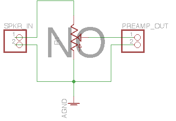
The simplistic approach would be to put the potentiometer straight across the speaker terminals. But then what happens if someone turns it up too far? Waaaay more power goes into the preamp input than is good for it, that’s what. Furthermore, it reduces the usable range of the potentiometer, making you fiddle with tiny adjustments at the very bottom end of its range.
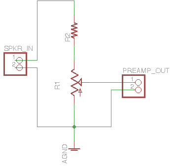
Instead, I built the circuit with a high-valued resistor in series with the potentiometer, limiting how much of the speaker signal can be sent to the preamp. And how much is that? Well, I had to figure out.
Resistor Values
I was guessing Jeremy’s receiver had 100W RMS outputs. My amplifier’s input specifications are for voltage, not power. So in order to know how to scale down the speaker signal to the appropriate preamp input voltage, I needed to find what RMS voltage was present at the speaker outputs — that is, in 100W driving an 8Ω load.
P = VI and I = V/R
so
P = V2/R
and
V = √PR = √100W * 8Ω = √800V2 ≈ 28V
That is, the receiver’s speaker outputs should be about 28V RMS when the receiver is playing at maximum volume.
Next, I needed to know the target input voltage of the external power amplifier. The A502 owners manual says its input range is 1V, and I decided to assume that meant RMS.
Dividing a 28V speaker output down to a 1V preamp input requires a 27:1 ratio in the voltage divider. If we do the calculation assuming that the pot is turned up to maximum, that means my 100kΩ pot needs a 2.7MΩ series resistor.
One final and very important point — I picked high-valued potentiometer and resistors knowing they’d be dissipating a very small amount of power from the receiver output. By way of comparison, a 1kΩ potentiometer placed straight across a 100W speaker output would be passing 28mA for about .78W power dissipation — a little high for a cheap potentiometer. With over a MΩ load, I could anticipate sub-mW power dissipation across my voltage divider.
Construction
I didn’t have 2.7MΩ resistors on hand; I only had 1.2MΩ (which I could series-chain to get 2.4MΩ) and 2.2MΩ.
Now, my calculation of 2.7MΩ was based on the potentiometer being turned up to its maximum setting. But I was well aware that I was making a lot of assumptions here about things like Jeremy’s amplifier output, RMS voltage versus peak-to-peak, interpretation of my amplifier’s input specifications, etc.
If I overestimated how much signal I needed to feed into my amp, the signal would be too high and the volume too loud, and we could use the potentiometer to turn it down (that being the whole point of using a pot). But if I underestimated and the maximum setting of the pot wasn’t loud enough, there’d be no way to get it louder.
With that in mind, and not feeling like soldering up more resistors than I needed to, I picked the 2.2MΩ resistors, giving a theoretical 22:1 ratio on the voltage divider and a theoretically correspondingly louder-than-calculated preamp signal going to my amp, theoretically allowing some room to turn the pot down from maximum and dial in the volume we wanted.
I now knew everything needed to gather my parts and start building.
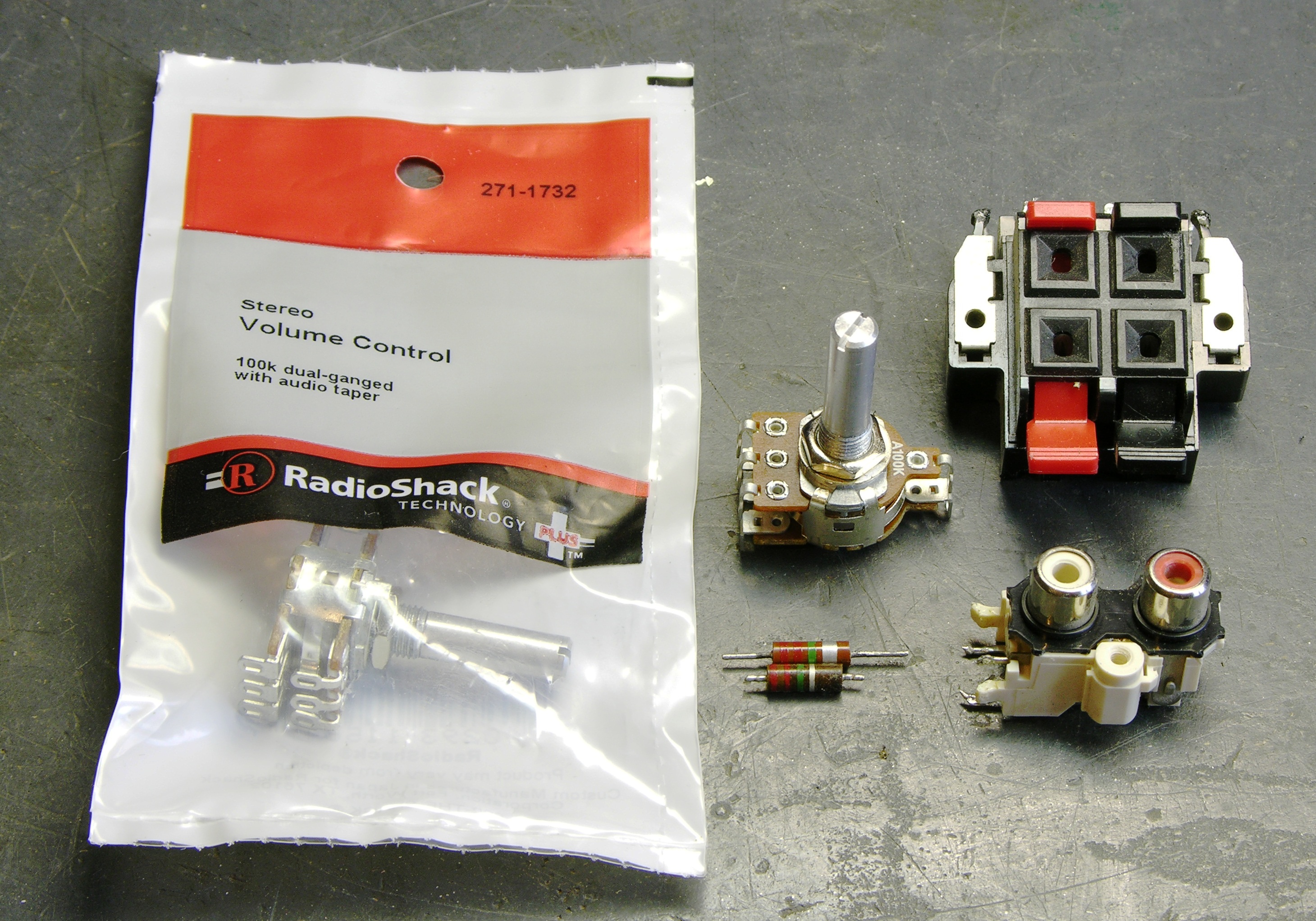
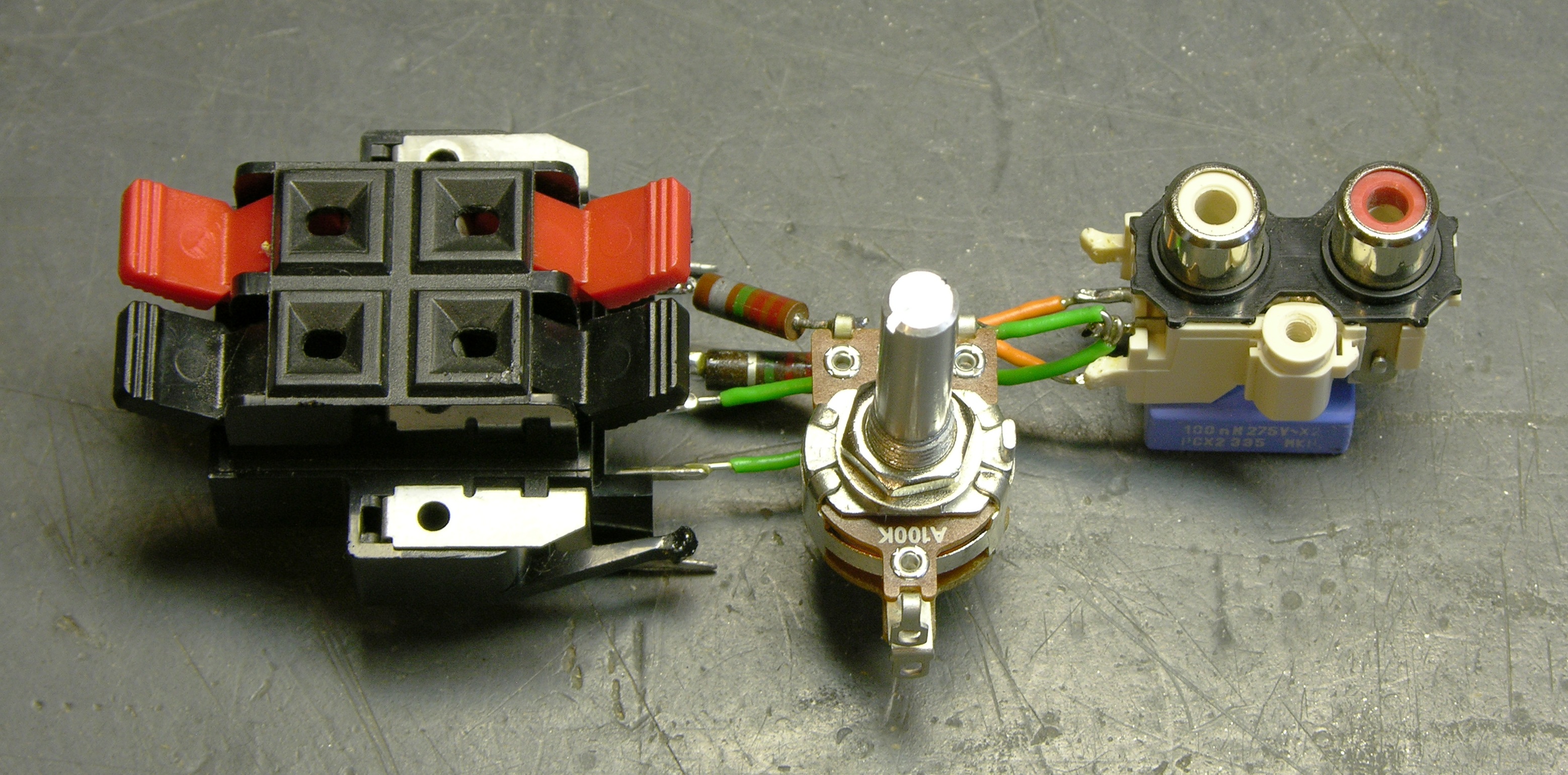
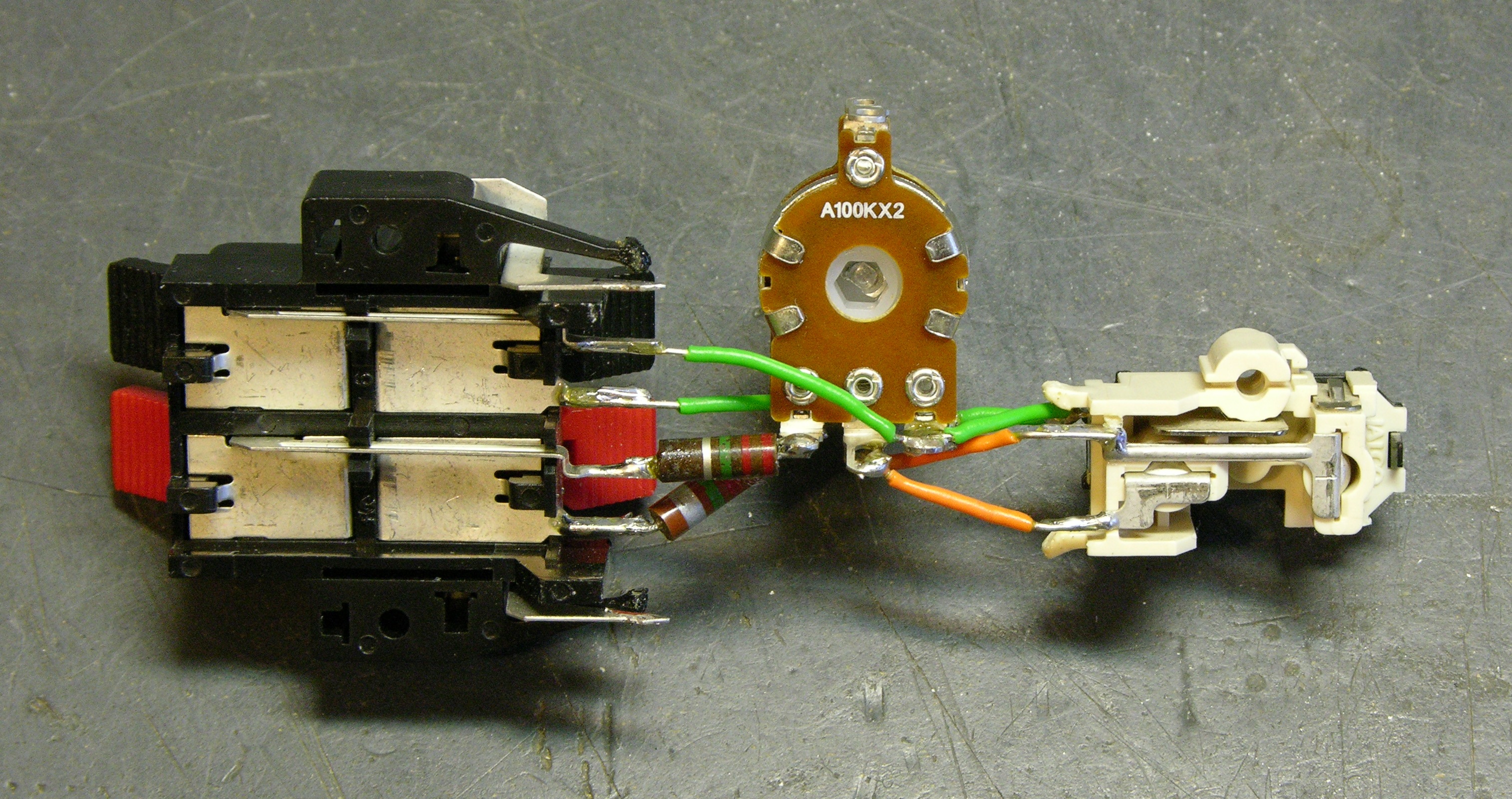
Stereo audio-taper 100KΩ pot from Radio Shack (can you believe I didn’t have any on hand???), speaker and RCA jacks from dead equipment.
I knew this was to be a temporary circuit for testing only, so I didn’t feel like finding a case to make it safe or anything. I just used the resistors to bridge from the speaker-jack inputs to the potentiometer and some wire to feed the “preamp” output RCA jacks.
Installation
On the way to Jeremy’s house, I stuffed the assembly in my pocket; and when I got there, not only was the cupboard bare, but one of my vintage resistors had got its end broken off.
Knowing I was going to have to rebuild it but wanting to test what we had so far, we hooked up the channel that still worked to drive Jeremy’s right speaker, leaving the left speaker powered directly by his receiver. This was actually a very good test, as even with the potentiometer all the way up, the speaker powered by my amp was a little quieter than the speaker powered by the receiver.
Jeremy had an even more limited selection of resistors, so I soldered up two sets of two series 1MΩ resistors and replaced both channels’ worth in the circuit. And then everything was hunky-dory — testing a channel at a time, we were able to dial in a volume comparable to his receiver.
And . . . no great moral to this story or anything. That was pretty much it. But it made for some brain work and calculation that I don’t do enough these days, and writing it up was a good exercise.
Oh, and Jeremy needs to figure out how to set the receiver’s bass cutoff frequency for his main speakers, because we’re both convinced that (regardless of which amp we’re using to power the speakers) we’re missing considerable bass that the receiver is misguidedly trying to send to a subwoofer.
Excellent write up, especially showing the “obvious” circuit that I would have started with and explaining why that would be a dumb move. I hate tutorials that pull perfectly formed circuits out of thin air and proceed to explain about 15% of why they work.
Solving real problems with bits’n'pieces. More please!
Hi, I keep an eye on your site, and by coincidence, an article on another blog http://synth-diy.blogspot.com/2009/02/it-wasnt-micas.html led me to a link that also discusses what you have achieved here http://www.musicfromouterspace.com/analogsynth/oddsandends.html#POTDIVIDER.
Keep up the good work. Cheers.
Depending on the capacitance of the preamp input and the connecting cable, lowpass effects could become considerable with such high resistor values used.
I’m told that some early solid state amplifiers could also have trouble with mismatched output impedances. Thus, if I were to build one, I’d probably start with a suitable high power, low resistance resistor to load the amplifier and go from there.
Of course, the early way of doing this was with an L-pad:
http://en.wikipedia.org/wiki/L_pad
And, if you needed to maintain both the input and output impedance, you’d use a T pad (This is especially true to minimize the high pass or low pass characteristics due to inductive or capacitive loading.). Building an adjustable T pad is, of course, not trivial.
Dave
Slightly off topic but I did find the following little mixer very useful and I think it may well do what you are looking for.
http://www.studiomaster.com/products/C3&C3X.htm
I’ve used it a number of times for corporate events where I don’t really need anything more than mixing a mic with a couple of cd players.
Appreciated sir, I need to know how many watts pmpo or rms the sae a502 shoots.
Many blown speakers… I am in panama
How I know which are the appropriate speakers.
I have to MTX bass.
Roberto, the A502 is rated for 200W per channel.