Back in May, I got this email from my friend J who works ER:
http://www.advancedcirculatory.com/CET/resqproduct.htm
I was at work last night and we had a code come in by ambulance. The Newton fire dept. now uses these when they code somebody. I saw that it had a circuit board and some LED’s and thought that you might be interested. It has been used but it I cleaned it up. Let me know if this is something that you want to take a look at.
“Code” is code blue, no respiration and no pulse. So J saved me a gizmo from a dead person, and “cleaned it up.” This is interesting. Wonder what it could be. I read the manufacturer’s web page and it doesn’t really enlighten me as to what kind of electronics are inside it.
I visit a few days later, and the gizmo looks like this:
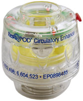
There’s a hole down the middle and a switch on the side. Turn on the switch and two red LEDs flash every six seconds. You plug the bottom end into a breathing mask and the top end into the CPR squeeze bag, and the lights tell you how often to squeeze for respiration for optimal (two-person) CPR timing.
A little bit of prying gets the case open, and the board pops right out.
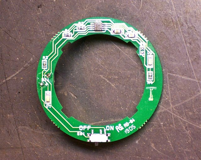
There’s not much to the circuit — the eight-pin chip is obviously what makes it work. My first thought is that it’s going to be a 555 timer, but it’s labelled “MBAC ZC5.” Google gets me nothing useful to identify the chip, so I draw out a copy of the PCB traces to see whether I can get anything out of the pinouts.
For my first pass, I place the components on the schematic corresponding with their physical placement on the board. (I actually did this on paper; when I translated to EAGLE, I didn’t have a library component for the mystery part, so I used a connector that had the pins numbered wrong. Heed the green numbers I added, not the grey ones.)
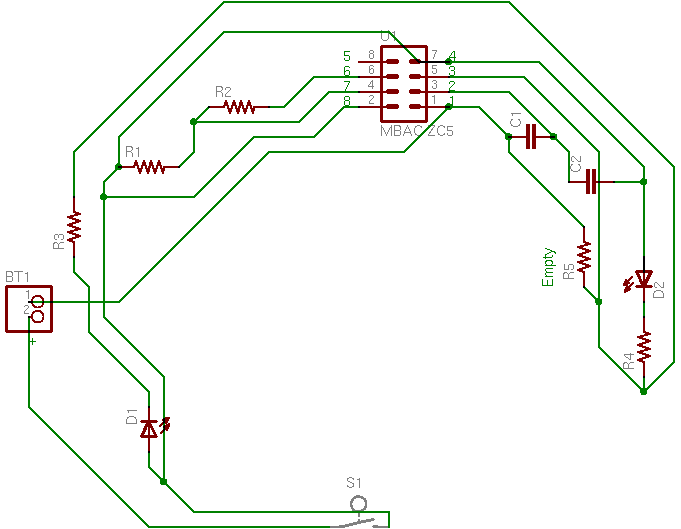
Then I slide things around based on a logical placement.
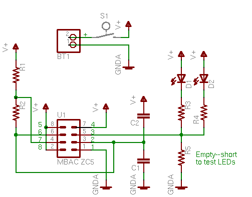
And this is starting to look awfully familiar — it is indeed the same pinout as a 555 in the astable multivibrator configuration, which makes perfect sense. In fact, the 555 circuit should have a connection from pin 2 (TRIGGER) to pin 6 (THRESHOLD) that I haven’t drawn — and when I look closely, I can see that it’s hidden underneath the chip.
So now I have a tiny SMT 555, a couple of red SMT LEDs, and a handful of SMT passives, plus a cell that’ll probably drive this thing for a long time. Cool.
The circuit causes a red LED to blink every 6 seconds. This is its sole purpose and is used to time ventilations. The device itself will work if the circuit is turned off. The device enhances blood flow to the heart, lungs and brain during CPR applied to a patient in cardiac arrest.