As mentioned previously, I was contacted this spring by Amanda McClellan of Coordinate It about an LED design project. Amanda is a civil engineer turned wedding planner and needs about a hundred lighted paper lanterns for a large reception on Labor Day weekend.
There don’t seem to be (m)any LED lighting solutions for paper lanterns, and Amanda was interested in the lower power consumption of LEDs without having to go around to each lantern to e.g. hook up LED throwies. She also indicated a willingness to advise me on packaging the system/solution to sell to other event planners out there, which sounds pretty good to me.
Between distractions, I’ve been working on a design for her. The prototype looks okay, and I think it’s about ready to send out to have boards manufactured.
Specifications
- Make LED drivers to power 10 lanterns with 2-3 white or warm white LEDs each, with some combination of parallel-series wiring.
- Cost should be not more than $2.50 per lantern, or possibly somewhat more if the system is completely reusable.
- Use constant-current drive, for the initial application in the 20mA range but ideally expandable to as high as 100mA.
- Ideally make the string(s) dimmable through optional analog and/or PWM input — but full-brightness when no dimming input is present.
- For Amanda’s use, pack 100 lanterns’ worth of drivers into a monolithic case for the sake of aesthetics and convenience.
- If easily done, make the same driver boards fit into fob-sized cases for smaller applications — Jeremy’s basement, interior lighting for CNC plastic-extrusion machines, etc.
- LEDs supplied separately. I don’t want to be in the business of soldering and testing LED strings that are going to get used by other people. It’s up to the customer to determine and meet their own LED requirements.
- If possible, run from 48VDC source, as I have several hundred 48VDC .38A power supplies I’d love to get rid of for the right price.
Driver Selection
I looked over a lot of LED string drivers before making my selection. Here are some drivers I considered and application notes I looked through:
- STCS1
- 40V max input
- no samples
- Maxim application note on high-brightness LED driver selection
- MAX16805/6 high-current linear drivers
- 5-40V input / 39V LED drive
- 35 – 350mA capacity
- I2C and analog dimming
- single string drive
- MAX16819/20 step-down drivers
- inductive step-down
- requires external inductors and MOSFET
- single string
- MAX16822A/B step-down drivers
- inductive step-down
- requires external inductors
- 6.5 – 65V input
- single string
- Maxim MAX16823 3-channel linear driver
- 5.5-40V supply
- 70mA/channel capacity
- per-channel PWM dimming
- 3-channel
- linear
- ultra-low external component requirement
- National press release
- LM3502 and LM3503 step-up converters
- inductive boost converters
- require external inductor
- 2.5 – 5.5V input
- single string
Given that Amanda wants 100 lanterns with 2 or 3 LEDs each, the 3-channel MAX16823 really leaped out at me. Even though some of the other drivers could support higher drive voltages hence more LEDs per string, the 16823′s three strings trump the higher voltages in the “power more LEDs per driver” category, hence providing a lower overall cost to drive large numbers of LEDs.
Because so many of the drivers have a maximum input of 40V, I gave up on using my 48V power supplies and looked for power supplies in the 24-36V range. I’m having a hard time finding power supplies in that voltage range whose price I consider reasonable, and it’s much worse for anything other than 24V, so it looks like that’s what it’ll be. I’d welcome suggestions on sources for inexpensive 24-40V ~1A power supplies, if you know of any.
With a white LED forward voltage drop at 3.4-3.6V and the MAX16823′s dropout voltage of .3-.7V, a 24V power supply could comfortably run 6 LEDs per string or 18 LEDs per driver. With 2 LEDs per lantern, that’s 9 lanterns; with 3 per lantern, it’s 6 lanterns per driver. It’d be nice to have an even 10 lanterns per driver, but I can live with this.
One nice thing about the MAX16823′s circuit is that it doesn’t require a fixed supply voltage or number of LEDs. Just leave a little headroom between your LED string series forward voltage and your supply voltage and you’re good to go. This means I can set it up for Amanda on 24V with 6 white LEDs per string, but Jeremy could use 12V with 3 LEDs per string, and someone with a 40V source wanting to power red LEDs at ~2V each could connect about 20 LEDs per string. That indifference to the details — as long as you don’t make the linear current controller sink way too much current — is really handy.
Circuit Design
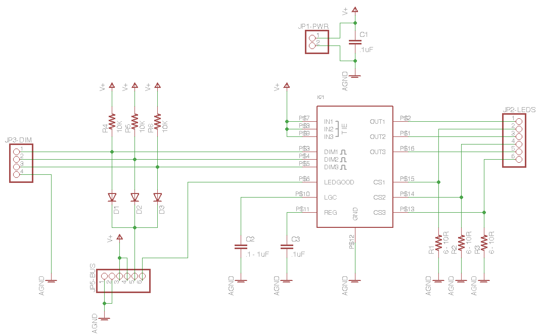
The schematic is pretty straightforward — some decoupling capacitors, current-sense resistors for the LED strings, and inputs for PWM dimming. Because I’d like the same board to work in a fob or plugged into a backplane in a larger case, I included dual power supply and PWM dimming inputs.
I figure if you have a large case of these (at least one I make), you’re more likely to want to dim all of the LEDs at the same time than to dim individual strings, so I used resistor-diode logic to tie the three dimming inputs together to a single dimming input pin on the backplane connector.
I also ran the “LEDGOOD” indicator output to the backplane, to invert and provide “LEDBAD” indicators on the monolithic case to show which strings are disconnected or having trouble. Having discussed it extensively with Jeremy (my first fob presale), I didn’t bother to provide LEDGOOD/LEDBAD indication on the board itself for the fob version — if you’re using the fob to power one to three strings, you can just look to see whether the LED strings are working or not.
Circuit Board
After laying out the circuit board, I tried my usual iron-on toner transfer to set up PCB etch resist, but I had much worse luck than usual and gave up. Tom McGuire graciously agreed to mill me a couple of boards at work and even provided pictures of their awesome commercial PCB mill doing its thing.
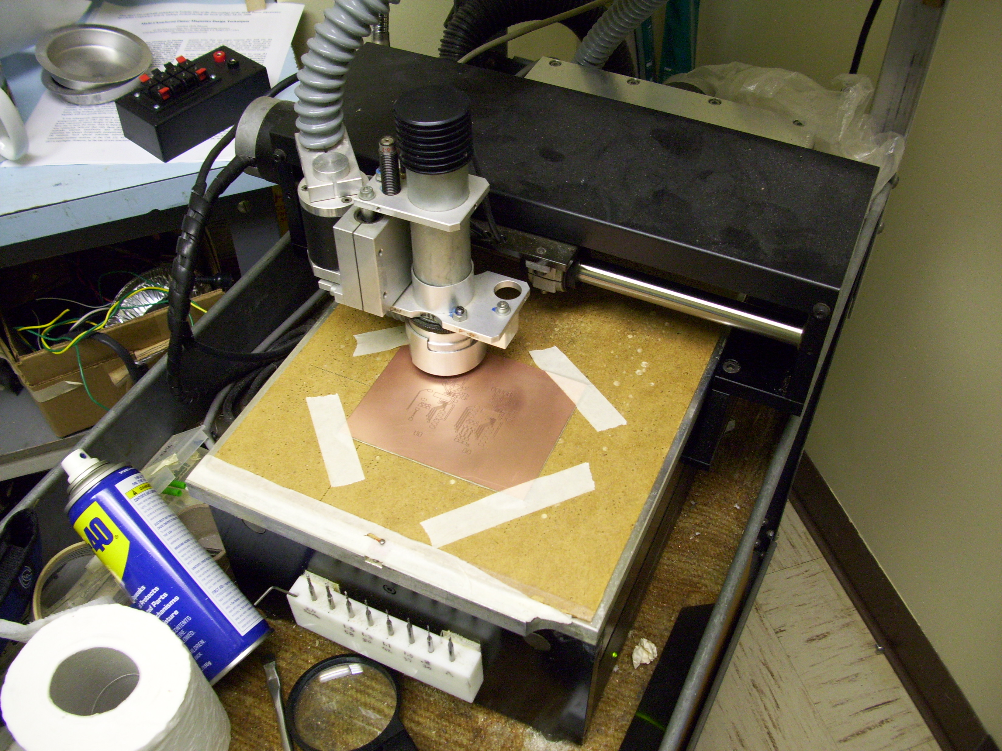
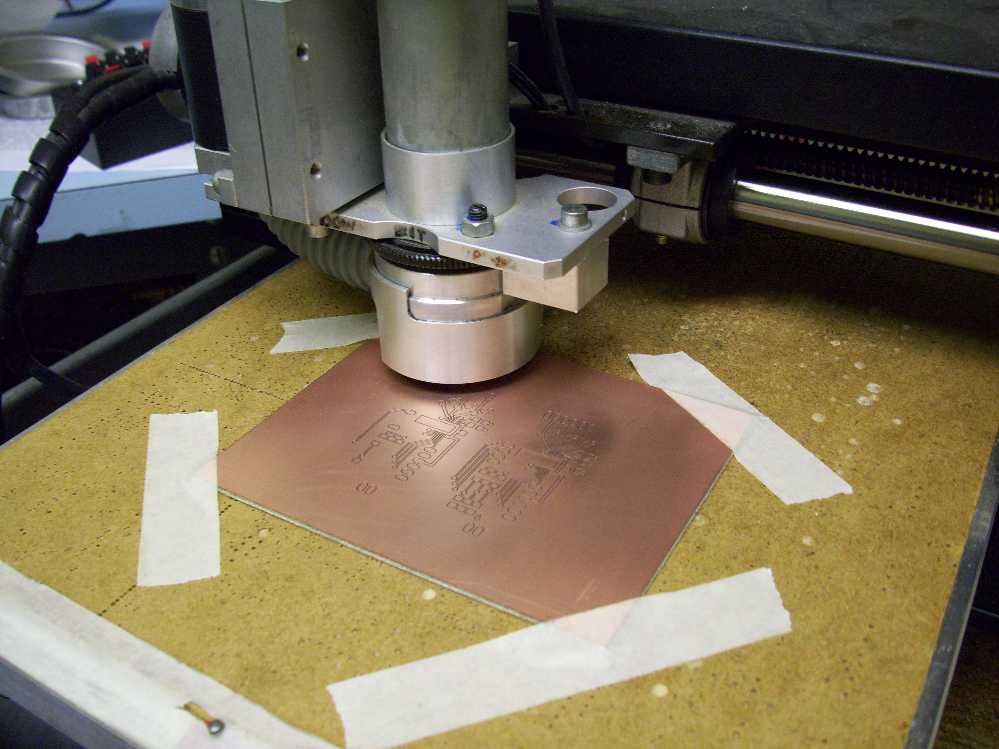
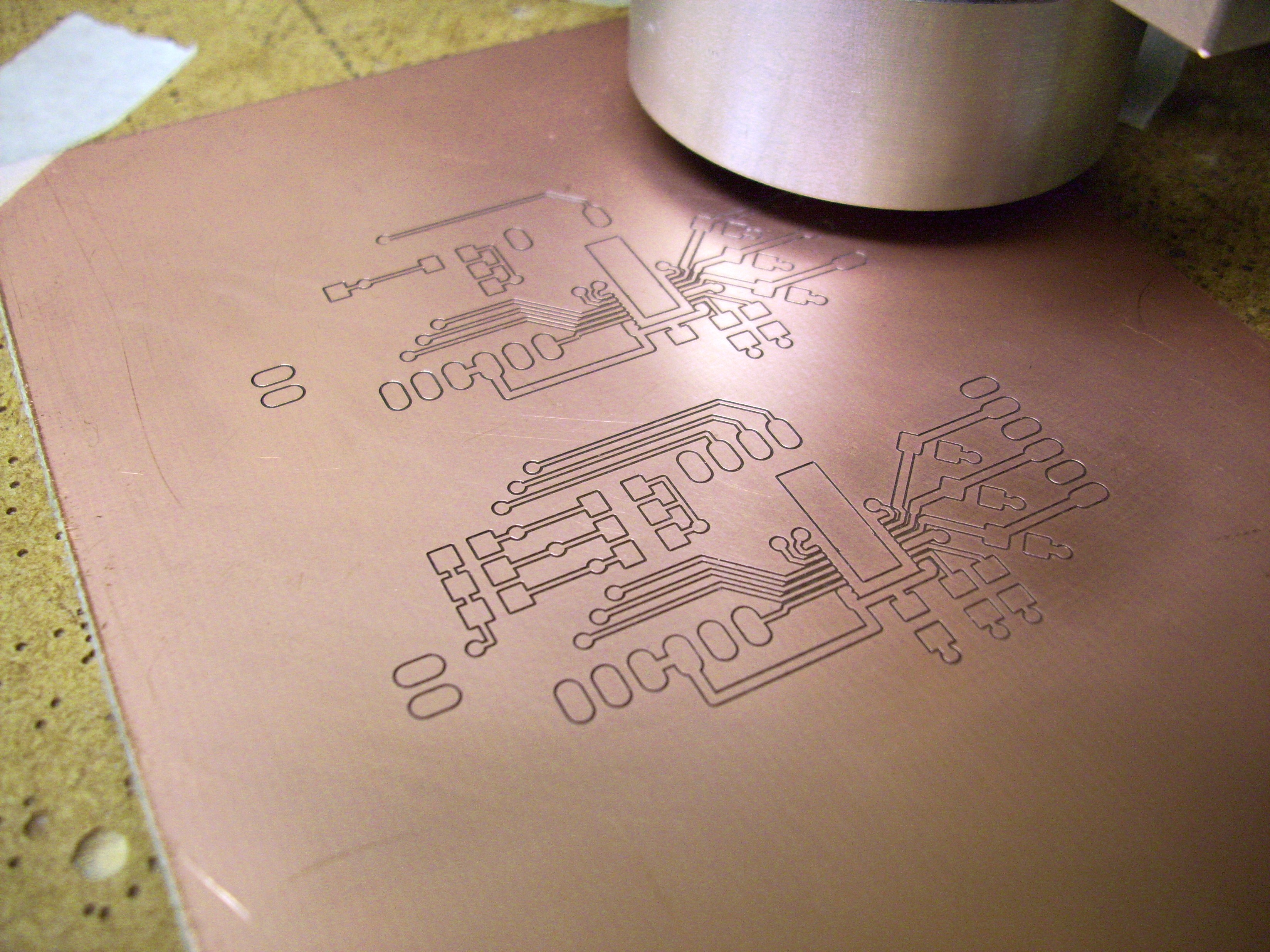
Here are my sad iron-on attempts shown next to Tom’s awesome milled boards.
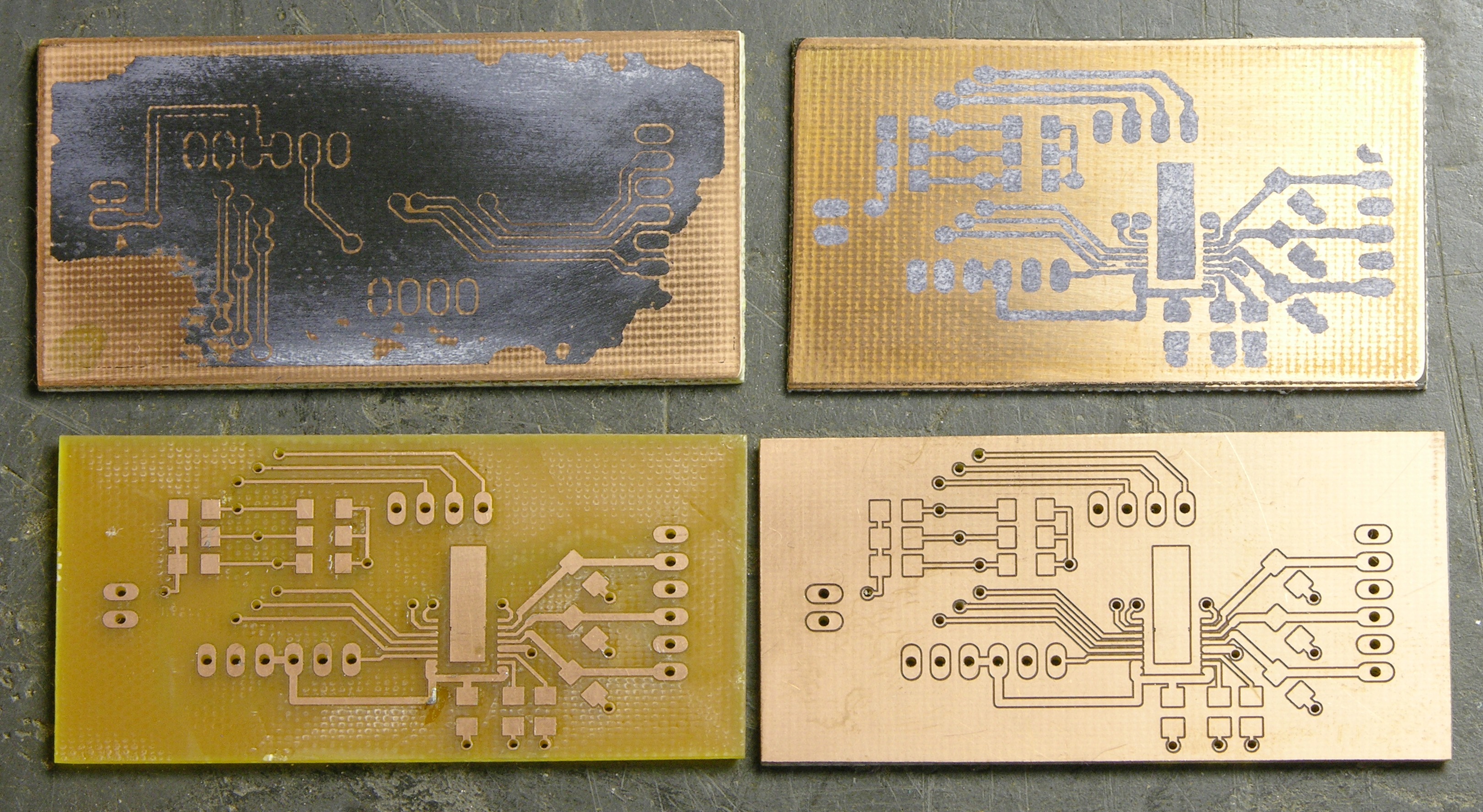
Tom “peeled” the waste copper from the top side of one of the boards, because he’s CRAZY.
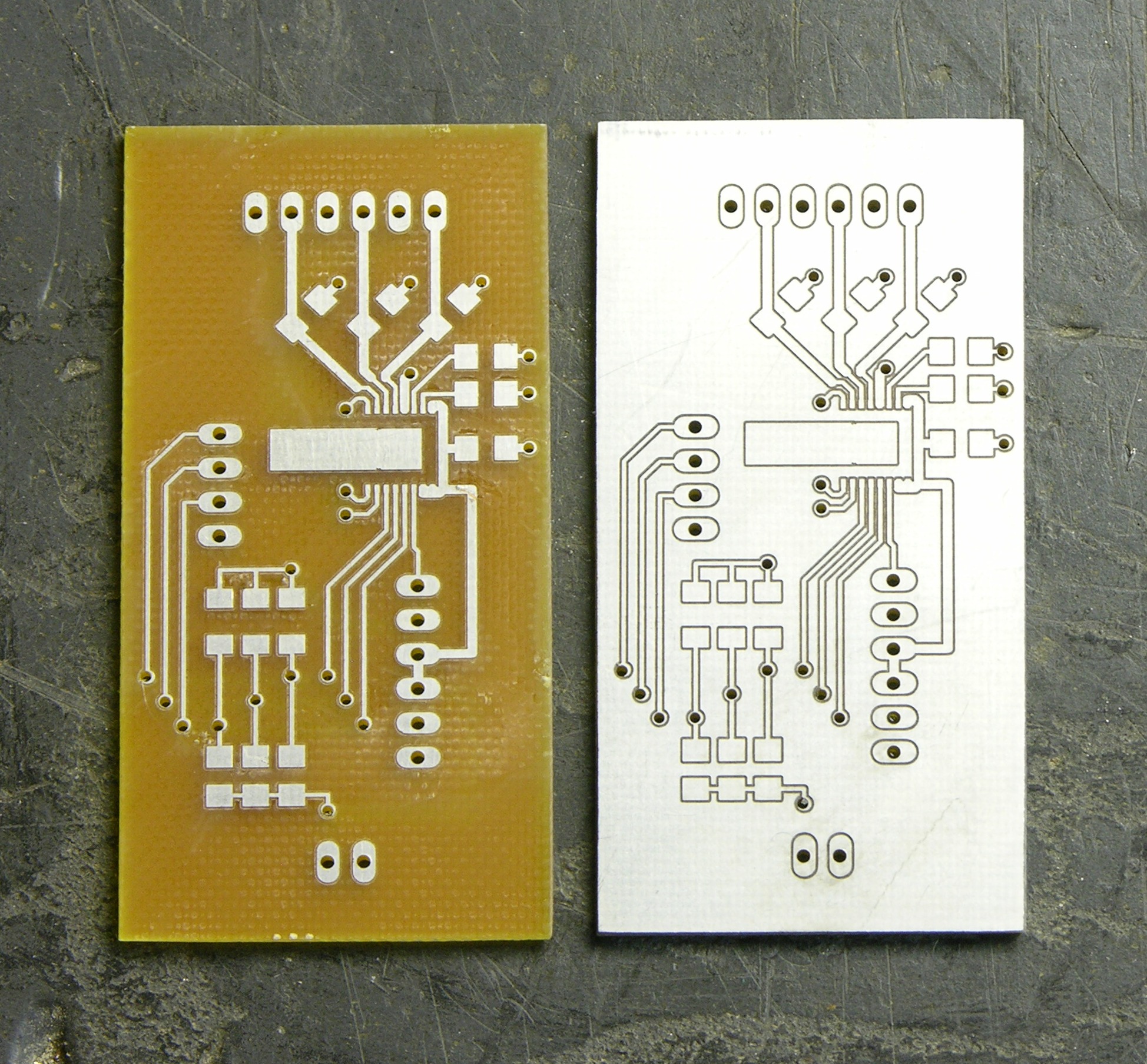
With Tinnit, verra nice.
Completed Prototype
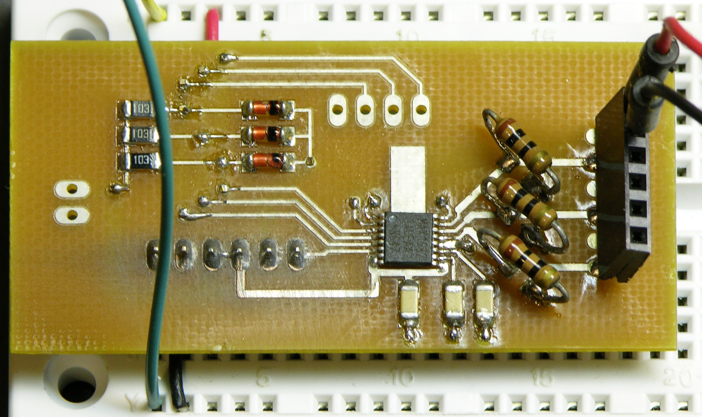
I assembled this a while back and actually don’t remember for sure whether I used the hotplate or hand-soldered and used braid to soak up solder bridges. Given the lack of waste flux around the driver IC, I think I did it on the hotplate.
I intend to use standard 1206 (or smaller) SMT diodes; but these cute round SMT diodes were on hand (salvaged from something) and they fit well enough. Sadly, I couldn’t find any .203V sense voltage / 20mA target current ≈ 10Ω current-sense SMT resistors in my bin; so as you can see, I improvised.
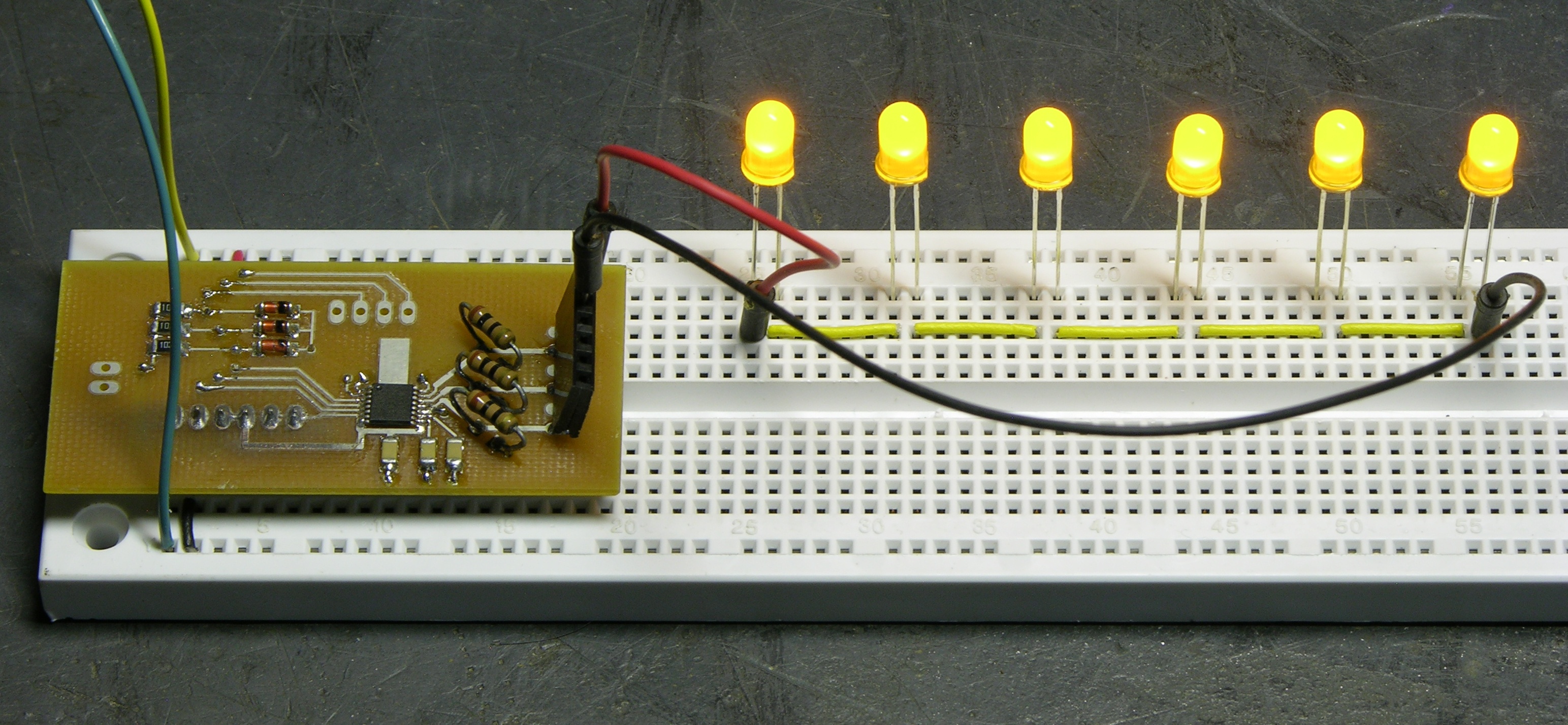
For now, I’ve populated only the connectors I need to test the prototype, and not even with the type of connectors to be used in the production versions. I bodged this together to work on a breadboard; but the real thing will have right-angle male headers for all the connectors.
The LEDs stay exactly the same brightness with a supply of 12-19V (as high as my slightly broken bench power supply will go),
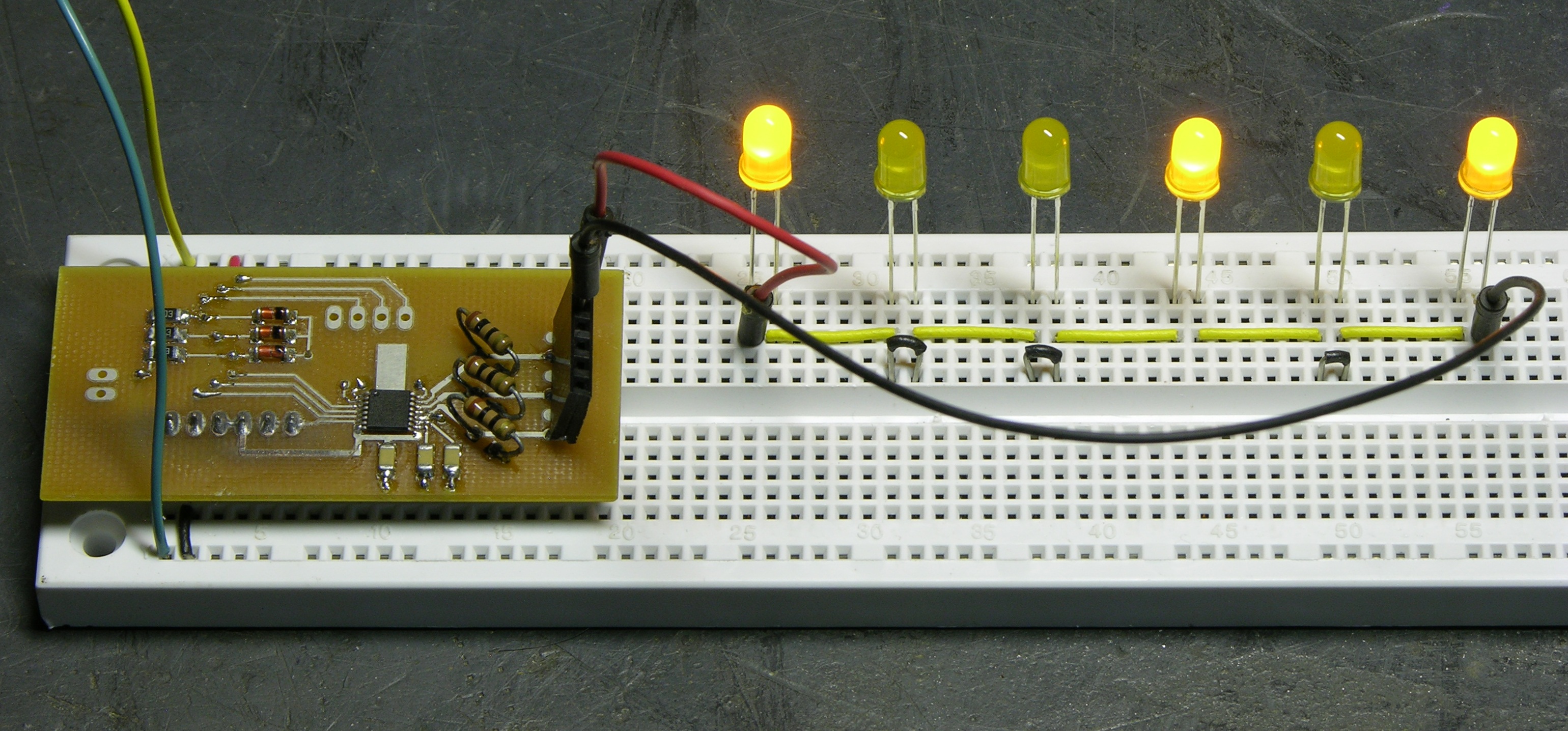
and also stay the same brightness with several of the LEDs shorted out to simulate a string of fewer LEDs. Looks like pretty good current regulation to me.
Next Steps
Right now I need to get boards built quickly for Amanda, so I’ll probably order a batch of 20 boards (enough for 120 or 180 lanterns) just like this, plus silkscreen labels for the connectors. But for the fob version, I want to include a power switch; so I already know there’ll be revisions coming.
I think when the time comes, I’ll print the fob cases using my CupCake.
Availability
I’d like to sell these to anyone who wants them, and I think they’re going to come to $20-25 each by the time I have the PCB, driver, passives, and connectors. (That feels like a lot to me; but in batches of 100, I think that’s about what it’s going to be.) I’m by no means ready to take orders, but I’d take a straw poll. If you think you might be interested, drop me a comment indicating
- likely quantity
- PC board only, fob version, or case with lots of boards
- configured for 20mA drive, something else, or you want to supply your own current-sense resistor
- or “$20-25 is just way too darn much for an LED string driver”
I promise I won’t hold you to it, unless you give me answer #4. ![]()
Hey keith,
Is there a way to measure the specifications of LED Strings — at least just enough info to start making a driver? (forward voltage, etc.)
To story here is that I am trying to find a DIY-friendly/cheap solution to drive the backlight portion of various aftermarket LED LCD panels. When I say DIY-friendly, I mean either off-the shelf ~20$ board or not to difficult to build from someone that just got himself an iron from radio shack (no TQFP soldering please).
For example, the following LCD Panel (the iPad screen):
http://www.beyondinfinite.com/lcd/Library/LG-Philips/LP097X02-SLA3.pdf
This one has 6 strings (of 6 leds). We have access to the “cathode” of each strings (and a “common anode”). The datasheet is not very verbose in terms of specification or they are not very clear.
Thanks!
——-
Side question: I recall that some LED driving circuit uses some sort of high-frequency to drive leds (for efficiency reasons)? Did I day-dream this?
Bernard, white LEDs have a forward drop of about 3.4V, so your strings of six probably want about 20.4V. Since you have a parallel-series arrangement, I’m guessing there’s a resistor in series with each series string and you just need to provide the appropriate drive voltage. Can you check whether there is, and what its value is?
I do not have the board in my hand (yet) but I know someone that has (just that it has difficulty probing it — it is 0.4mm pitch connector and this is its first time using a multi-meter.) He says the reading is not making sense (MM is not auto ranging and he tried many Ohm ranges without making sense of the reading).
I was reading on (W)LED drivers and I never see resistors with the leds in the app notes. The LED Strings are connected directly to the chip. For example, the O2 Micro one (which some believe is close to what is in the iPad circuitry) OZ9956C http://www.o2micro.com/prods/o2m_int_ltg_brochure.pdf
If you feed the appropriate voltage and current to a LED String and then you start lowering the voltage, will the LEDs dim equally?