In order to show off the ADXL202 tilt sensor, I want to hook up two LEDs that brighten and dim in response to the tilt. Because the sensor is +/- 2g, my PWM duty cycle is only varying from 25% to 75%, which isn’t enough to see the variation in brightness of my LEDs. Somehow, I have to translate that into a range that varies down to near 0%.
My ultimate plan for the tilt sensor involves controlling a motor (duh), and I expect to experiment with several different drive logic configurations. Regardless of how I end up driving the motor, though, it’d be nice to have indicator LEDs to demonstrate what decisions are being made and fed to the motor–so even if I don’t need any additional circuitry for the motor drive, I’d like to get the LEDs working.
I had previously considered, and am now looking carefully, at using a phase-locked loop (PLL) to help decode the PWM signal. A PLL locks onto the input frequency and provides an output signal of the same frequency–but with 50% duty cycle. A Type II PLL is edge-triggered, so it provides an in-phase output. (A Type I PLL’s output is nominally 90 degrees out of phase for a 50% duty cycle input.)
So if I can manage to get a PLL to work, I can use it to lock onto the fixed frequency of the tilt sensor’s output, and give me a reference signal that goes high at the same time as each pulse of the sensor, but goes low at exactly half of the signal period, while the sensor’s signal is going lower earlier or later depending on its tilt. Then instead of looking at the raw sensor data with a duty cycle range of 25% to 75%, I can compare the sensor to the reference and get “left” and “right” signals with duty cycles each varying from 0% to 25%.
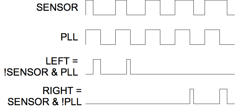
That means the LEDs would both be dark when the device is level, instead of each varying from dark to bright over the whole range–but I can live with that. It also means the LEDs will give a very direct representation of what I need the motor to do.
So I picked up a couple of 4046 PLL chips, and I’ve been reading the datasheets. Many, many times. After three or four readings, I understood that they were really going to do what I want with their Type II phase detectors. After another three or four readings, I think I have a pretty good idea how to select external components to set the frequency capture range I need. I don’t think I’m stupid–I’ve just never worked with these before.
I’m itching to try it out.