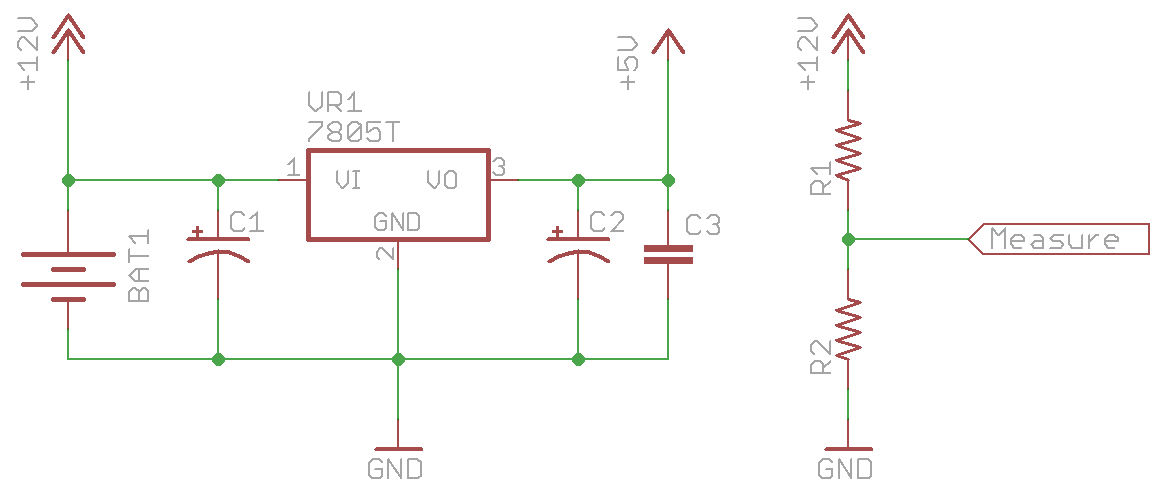
Hey, real EE types out there, is there any reason I can’t monitor 12V battery voltage using a simple voltage divider into an A/D input of a microcontroller that’s powered by a voltage regulator on that same battery?
This seems straightforward, but I ask because there seem to be a lot of fancy circuits and devices out there for monitoring supply voltage. It seems to me they all revolve around monitoring the device’s own VCC and where to get a reliable AREF when you don’t trust your own supply.
In the case of monitoring a battery voltage that will always be much higher than the dropout of the voltage regulator powering the microcontroller which generates its own AREF, I can’t think of any reason to get fancier than this.
I would Just Do It but I don’t have a good test setup for this and I’m getting ready to commit it to a board layout.
Note: I’m not a Real EE™ so these might not even be real issues.
It’ll probably work ‘good enough’. The only thing that I’d worry about with that is is the mico’s input impedance and I suppose the (admittedly low) power lost in the divider. Just take the input impedance into account and I don’t see any real problems with it.
If you really wanted to you could hookup an opamp with a negative gain, but that’ll probably waste more power anyway.
You can, but you have to remember that the voltage the battery puts out will vary with how much current is being drawn. At 10mA you might read 5V, at 20mA, 4.8V, and at 30mA 4.2V (these values are mostly made up). The point is, to get a realistic impression of how much charge there is left in a battery, you also need to have some idea of how much current is coming out of the battery at the same time you are measuring the voltage.
More importantly, a drained battery under no load will put out a voltage very similar to a fully charged battery under no load. In other words, you don’t know a battery is drained or not until you try and use it.
If you are using a micro-controller, you can either measure the average current draw at certain points in your program, or have a “battery test routine” that will draw a fairly constant current and then you can measure the voltage during that time. After that, find an approximate battery drain curve and bingo, you have an estimate of how much charge you have left in your battery.
Google for data on a battery discharge curve similar to one you are using.
Vanquish, all good points; thanks for identifying that my question was too general!
This is a 7.2Ah sealed lead-acid battery feeding a microcontroller-and-LED circuit drawing about 20mA most of the time and about 400mA (I don’t remember the exact amount) once in a while.
My goal is to shut the sculpture down into an ultra-low-power mode when the battery is too discharged to be useful anyway, so we stop having to take it out of the gallery for a day to charge it when the gallery staff forget to charge it overnight and leave it on for several days straight anyway.
“Hey, why’s that red light flashing and it’s not doing the usual things?”
“I dunno, did you forget to charge it again?”
I can make a point to sample when it’s quiesced. Since the current draw then is about C/360 — or if I measure between LED pulses, probably < C/10,000 — I think I'll be close enough to open-circuit voltage to get a meaningful measurement. Fair enough?
Vanquish said everything I was going to say but I wanted to comment on a cheap and dirty way of testing a battery. You can connect a low value resistor (to pull a load on the battery) in parallel to your voltage divider then connect these both to a to a FET. When you want to check the battery voltage just turn of the FET for a few milliseconds, check the battery voltage then turn off the FET.
Your most meaningful measurements are under the highest load, not the smallest.
Think of the battery like a spring – the more charge that is in the battery, the stiffer the spring. If you push really hard on really stiff spring (or load a fully charged battery with a high C), it’s only going to compress a tiny bit (or drop a little of it’s nominal voltage). But as the battery drains, it weakens. If you apply the same weight to a weaker spring, it compresses much more. But, when you take the weight off, both springs are exactly the same height (assuming they started off the same height, of course). You can’t really tell which is the weaker spring (battery) just by comparing their height (voltage) when there is no weight (load) on them.
What you are really interested in is how much oomph the battery has left in it, so you want to apply a fairly substantial known load to your battery, and measure how far from the nominal voltage it drops. This will give you an indication how far along the typical discharge curve it has progressed.
Vanquish, Luke –
What you say is certainly true for load-testing a battery, which I think of more when asking where the battery is in its overall lifespan (is it worth continuing to charge and discharge) rather than how much is left of a particular charge. I’m interested in how much of the current charge is left.
I’ve seen a couple of apparently-reliable online sources that claim a lead-acid battery’s % charge can be determined quite accurately by measuring its unloaded voltage. This was what I was aiming for with the quiesced system.
If those claims are bogus, I can always turn on all the lights and take a voltage reading with the system as loaded as I can get it.
I hope this works as it’s what I have in mind for a much bigger battery. In particular, I want to track the voltages of individual cells in a 24 V battery for an off-grid house.
One tweak I’ve considered, which I’m not sure is worthwhile, is to have a zener diode in series with R1 so that the voltage at the measurement node more directly tracks, with an offset, the battery voltage to make better use of the ADC’s range. Selecting suitable zeners for each cell-pair connection node would allow broadly similar levels of measurement precision across the cells of the battery. I worry about temperature effects on the zeners, though.
Ed Davies: A Zener in itself is not really “stiff”, so the zener-voltage will depend quite heavily on the current going through it. As you want to run as little current as possible through the zener, it will not regulate well. Also keep in mind the variations with temperature that also will be different for z-diodes with different nominal voltages.
(an exaggerated U-I-graph is on http://hyperphysics.phy-astr.gsu.edu/hbase/solids/zener.html )
Just use a voltage divider made up from precision resistors (and a trimpot to adjust away the remaining variations) and go into a differential ADC. If the remaining leakage current is too much cut the line with a simple mosfet when not in use.
Chris
Sounds like for what you are doing its a suitable solution (and obviously already been debated). The only consideration I will suggest is what kind of lead-acid you are planning on using? Most are only suggested to be discharged up to 50% of their capacity which with this topology would be quite difficult to predict. If you want to get really fancy you might be able to look into a coulomb counter (or add a differential across a small shunt). Assuming you aren’t too worried about the depth of discharge I think you can reasonably approximate monitoring your ~C/360 point through trial and error (this could be affected by C1 depending on the magnitude). If you want to maximize your ADC range you can just buffer the output with a unity op-amp.
Some years back, I wrote the software for a solar/SLA powered installation desgined by a “real EE” that did exactly that.
Worked for us, and I’ve always done it the same way since.
Another thing to be careful of (as if you didn’t have enough to consider) is that ADCs “like” a relatively low input impedance. If you are using a potential divider with high values to minimise current drain, you won’t have that. This is particularly a problem if you are using a multiplexer so you can read several inputs. In this case, you have the capacitive load to consider as well. As mentioned above, a op-amp buffer will solve that for you but at the cost of more power and complexity.
I like Luke S’ idea of using a FET to turn off the divider when you are not using it. That way, you can have a “stiff” divider that doubles as a battery test load and still keep minimal (average) battery consumption.
VRLA’s are fairly well characterized – the open circuit voltage (Voc) correlates with the state-of-charge (SoC) and with temperature. There is a memory effect whereby Voc will be mis-read if the battery was previously under load – need to wait some time with no load. Keep in mind that the internal impedance increases with discharge (and Voc drops with discharge). If your load is well characterized, other than temp comp, you just need to know the terminal voltage. Lead Acid tempco is roughly -30 mV/°C. See: http://www.panasonic.com/industrial/includes/pdf/Panasonic_VRLA_LC-R127R2P.pdf and http://www.altestore.com/howto/Batteries-Measuring-State-of-Charge/a81/
Most gadgets these days either don’t monitor SoC or use some type of coulomb counter (aka current integrator). This would require a low-value resistor (limit measurement loss) in the current return path and a jellybean opamp (with rail-to-rail capability… not so jellybean I guess) with some gain/lowpass for your ADC.
In my opinion (not a EE) your circuit will work. If you consumption is repetitive and you can draw your discharge curve (easy with a mc: http://www.google.es/search?q=battery+discharge+curve&tbm=isch), you only need to set the Idle-mode point in a voltage before the “knee” of the curve.
Regards.
I agree with Andrés, you should get adequate results with your system. I did some basic tests with a similar set up (lead acid battery, charged by solar) and it was accurate enough to give a rough estimate of available time left before shutdown.
Most cheap electronics use something similar but built into an IC. Might be worth looking for some battery monitoring chips.
You don’t say what uproc you are using but AVRs have a couple of useful features. The first is protection diodes on the pins which will prevent damage to the AVR if the voltage is too high (assuming low enough current!) which can be handy when you want to charge the battery in circuit. Many also have an analogue comparator that you can use to measure voltage drop over a resistor to calculator current draw. If cost isn’t an issue then a hall effect sensor and op-amp to scale it is a better option though.
Came to this late, but wanted to post one nugget now that I found it.
Use the voltage divider approach, but to minimize current when you’re not measuring, ground the bottom of the divider using one of your micro pins (held low). When you’re not using the divider, hold that pin high, and no current is wasted when not measuring. Voila!
Or rather, less is wasted (your micro’s high isn’t as high as the battery’s)…
Or this, three small resistors, two pins, and no residual drain:
1. VBATT–>5K ohm–>(Pt A)–>5K ohm–>(Pt B)–>100K ohm–>VBATT
2. Connect (Pt A) to your A2D port
3. Connect (Pt B) to an open drain output (hopefully you have one) of your microcontroller.
If you drive (Pt B) low with your open drain output, you can read 1/2 VBATT at (Pt A). When (Pt B) is high impedance, no current flows (both ends of the chain are at VBATT.