Background
Steve Wilson is a graduate student involved in WSU’s CRATEL (Center for Research in Art, Technology, Education, and Learning) program, and his video synthesizer was sponsored for further development in last year’s BETA (Bridging Entrepreneurship, Technology, and the Arts) competition.
One of Steve’s challenges for his video synth, and an interest in general, is creating expressive interfaces to electronic instruments. He describes it in a post to the Technology: Art and Sound by Design class mailing list. Basically, it comes down to the idea that acoustic instruments offer an immense amount of control over the sound that comes out through physical manipulation, and electronic instruments tend to offer much less control, and through mechanisms mainly like knobs and sliders.
While brainstorming with Steve about his synth, several of us came up with the idea of an interface like a plasma globe, which you control by moving your fingers over the surface. A cheap videocamera inside could watch what was happening and control the action.
Apparently a group of engineering students have been working on the globe subproject for six months without much progress to report. Although their difficulties seem to be mainly lack of organization and lack of time, others of us had talked about how clear an image might be obtainable on the camera with the globe lighted from the inside or outside.
Finally it occurred to me (while driving home from work) that gloves with LEDs on the fingertips would make lighted spots that should be very easy to see from the inside of the globe. Different colored LEDs on different fingers would allow the driver software to identify the different fingers; and pressing the LED against a translucent surface will produce a sharper point than holding it further away, so it might even be possible to determine approximately how near a fingertip is to the globe’s surface. And if made properly, the glove could be worn without impeding other use of the hand–just adding lights for the globe.
Time to prototype.
Gloves
I was hoping to find a cheap lycra glove to make something like the original Dataglove. (Yes, I have a Dataglove system. No, you can’t play with it.) What I found instead was certainly cheap, but knit cotton instead of lycra. Heck, for 96¢, it was good enough.
When I put the gloves on, I could feel that they’d been assembled somewhat sloppily. Inside-out, it was easy to see that there was a lot of extra fabric inside the fingers outside the stitching:
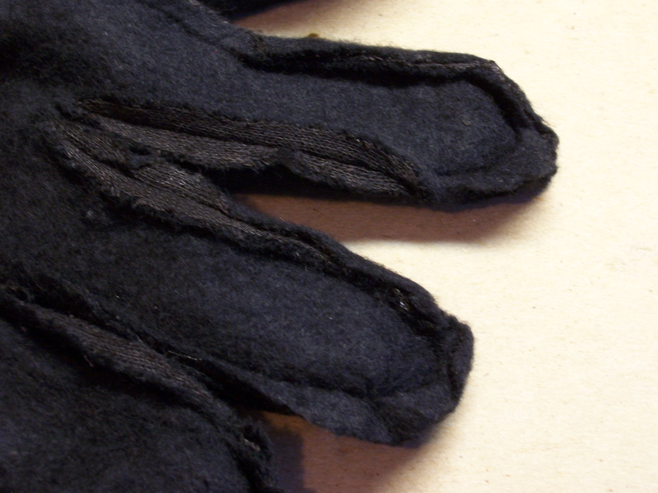
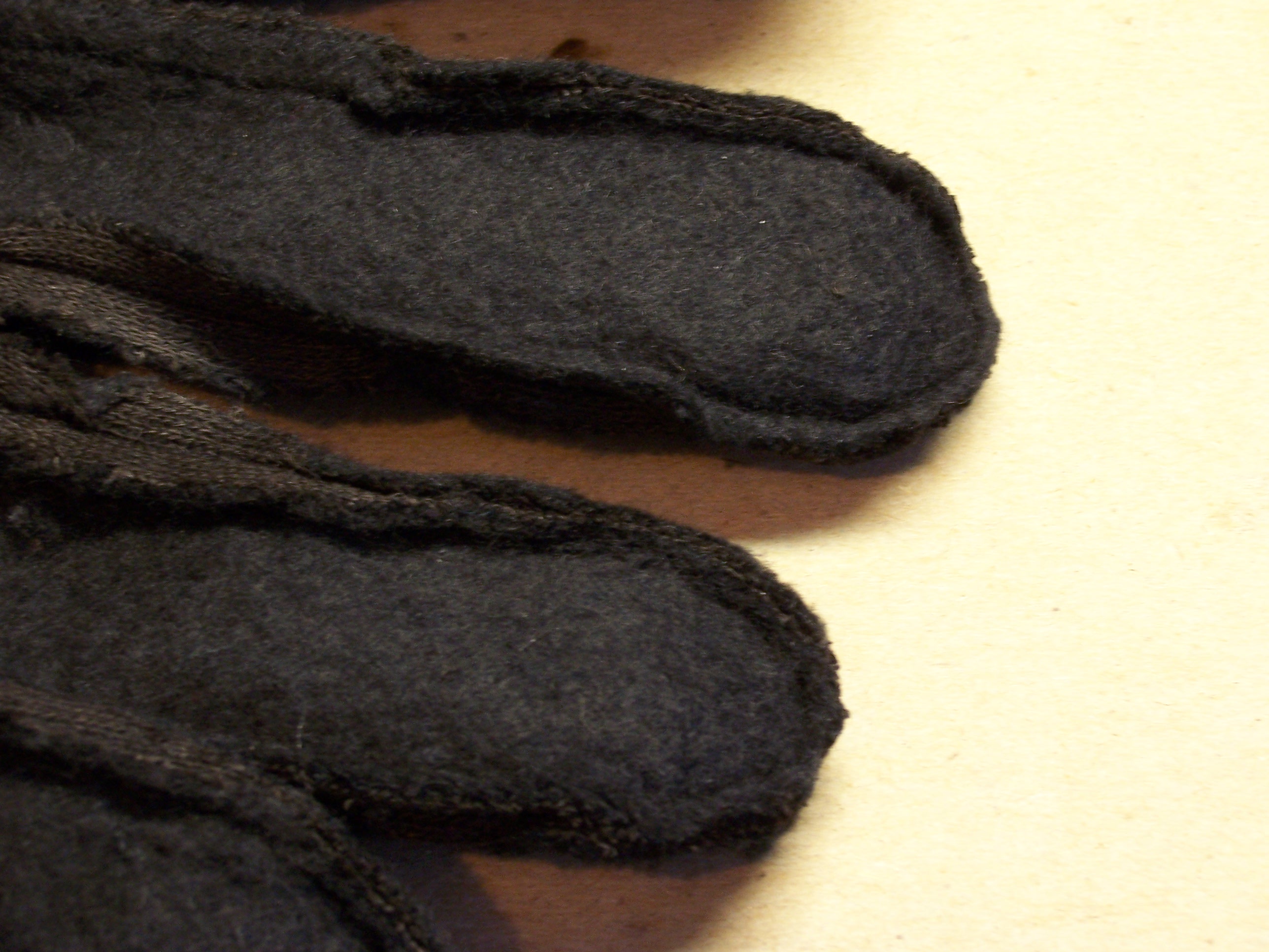
So I trimmed it a little closer and more evenly around the fingertips, for better fit and comfort.
LEDs
I wanted to use surface-mount technology (SMT) LEDs, so they’d fit flat against the glove surface. The ones in my stockpile are out of broken digital office phones, used to light up beside the line appearance and feature buttons.
I wanted to be sure I knew the polarity before I started attaching things and soldering them together, so I tested first with my meter. The LEDs actually lit with the small amount of current it supplies, which was kind of cool. Curiously, the green LEDs have the anode on the end with the cut corner, and the red LEDs have the cathode on the end with the cut corner. On each LED that I identified, I marked the anode end with the color of the LED. (The ones on this sheet are tinted to indicate their color, but the ones I’d already removed weren’t.)
The phone flex-PCB has a 300Ω resistor in series with each LED, so I tried out a couple there on the strip. Nice and bright.

Soldering the LEDs
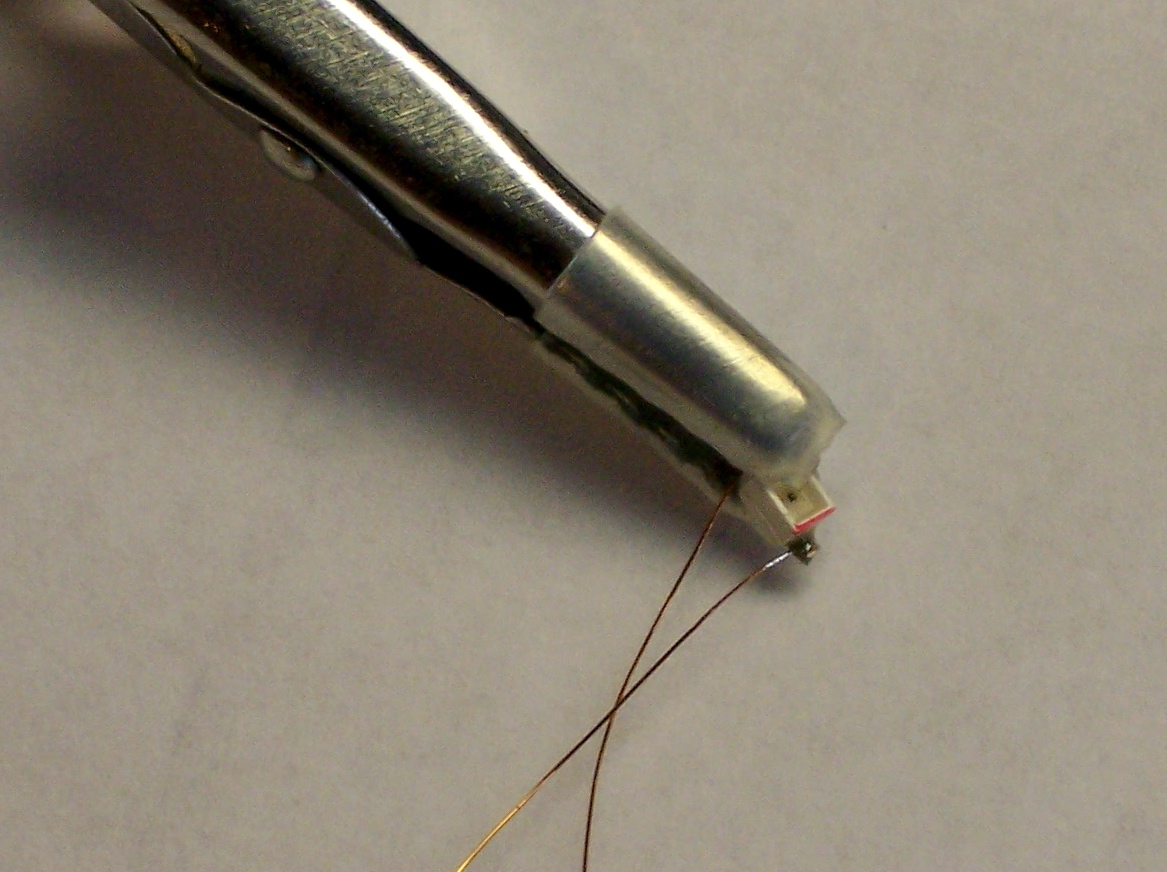
My plan was to solder wire the LEDs, then sew the wire through the glove to the back side, where I wanted to attach a battery holder. I got out some fine wire, scraped off the enamel insulation, wrapped it around the fly leads on the LED, and soldered it up.
Sewing
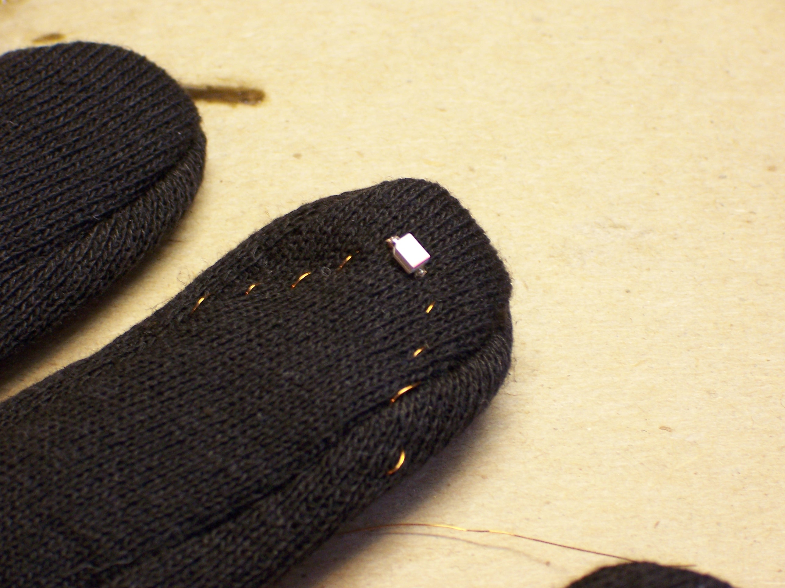
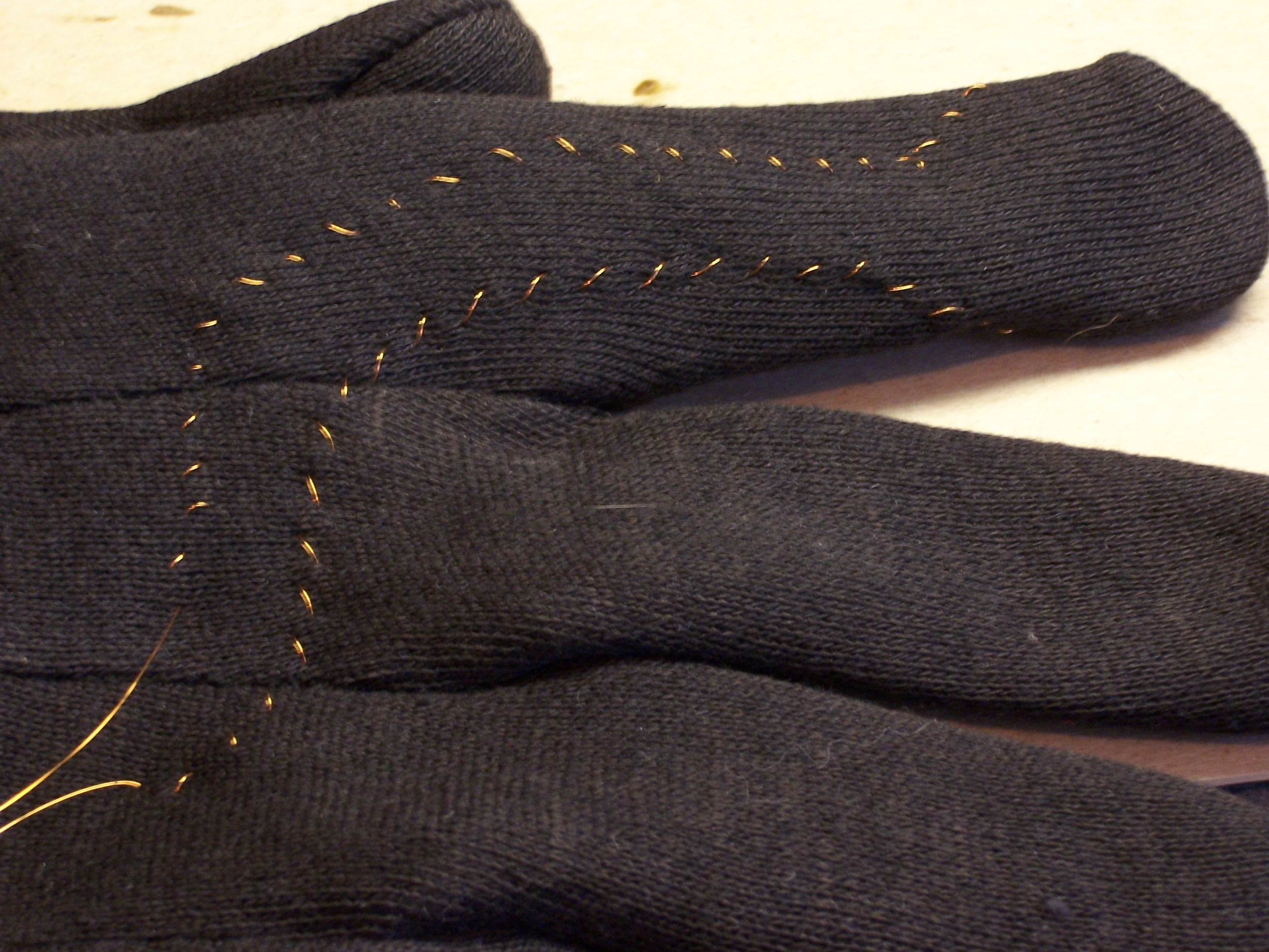
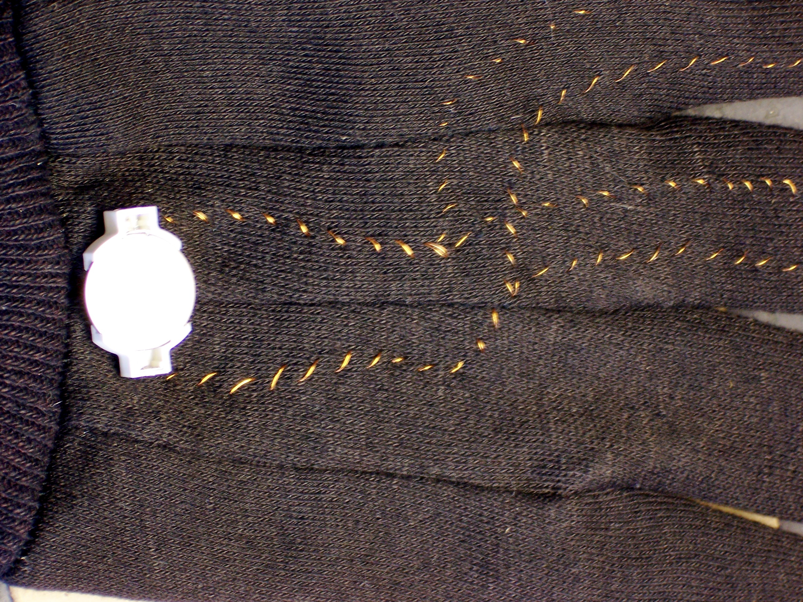
After I had both wires soldered to the LED, I threaded one at a time through a needle, held the LED about where I thought I wanted it on the fingertip, and started sewing. The goal was to get the wire from the tip of the finger to the back of the hand without leaving any large loops that might snag on anything, and without reducing the stretchiness of the glove. The latter factor called for a zig-zag stitch, which with a single thread looks like a running pattern of slash marks.
Once I got the wire stitched around to the back side, I followed along the back of the finger and then curved toward the center of the back of the hand.
Glue for Protection
I needed something to protect the LEDs on the fingertips so they wouldn’t snag. When the wires were safely stitched around out of the way, I got out the hot glue gun, put on the glove, put a dot of molten glue over the LED, and pressed the glue into a perfectly-shaped dimple in a USB serial connecter that I lifted from the CRATEL lab. It soaked into the fabric a bit, adhered very well, and made a nice smooth bubble over the LED.
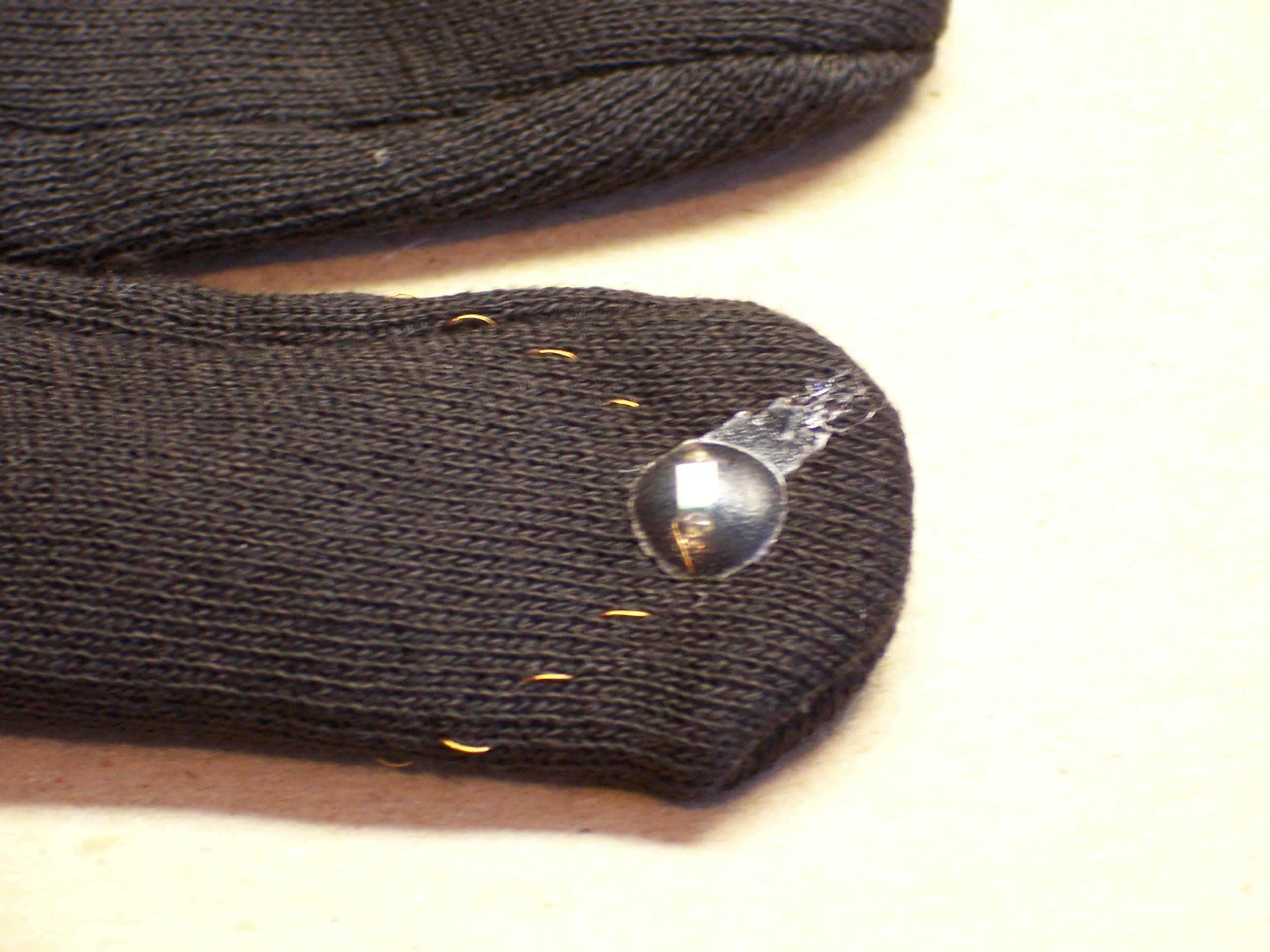
Well, mostly nice and smooth. Hot glue tends to stretch like pizza cheese, and I made a little boo-boo.
Battery Holder
For now, I settled on prototyping just two fingers, because I have only two colors of SMT LEDs, and because it seemed like enough for a proof of concept. I steered the appropriate wires onto the same paths and ran them up to where I wanted the battery holder.
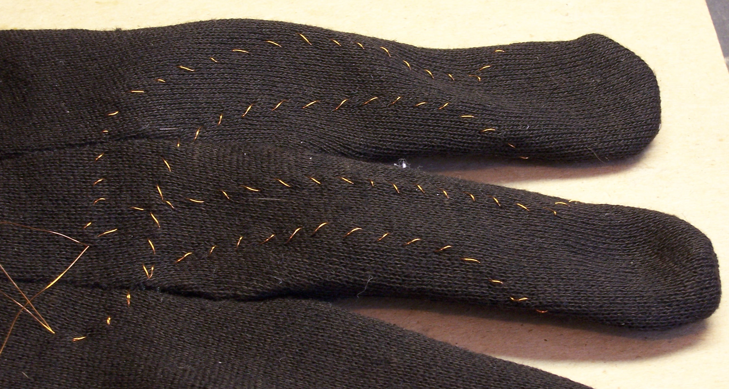
Then I clipped the wires short, scraped the ends, folded the glove over to get room to work, and wrapped the wires around the leads of a surface-mount coin-cell holder salvaged from a PC motherboard.
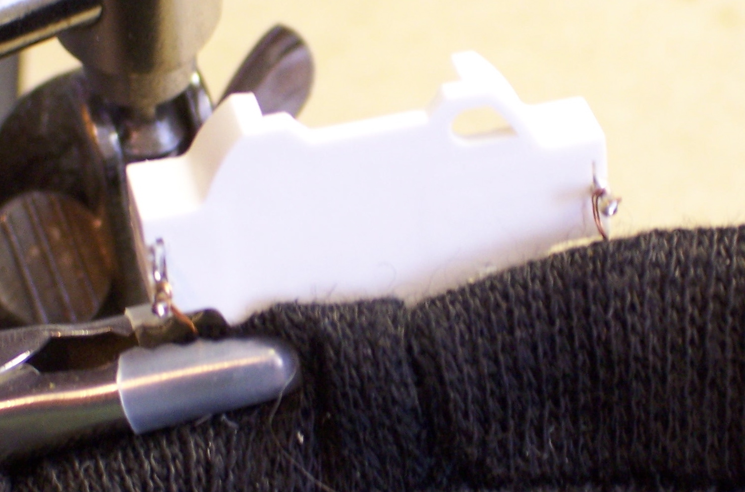
I soldered them on, then folded the battery holder leads underneath so they wouldn’t poke through the glove and scratch up the hand. Laid back out, it looked like this.
The Lights
I didn’t bother with a switch on the prototype–just pop in the coin cell and the LEDs come on. And because I’m using an old, small battery, I didn’t bother with current-limiting resistors–the internal resistance of the battery seems to be enough to limit the current to the LEDs.
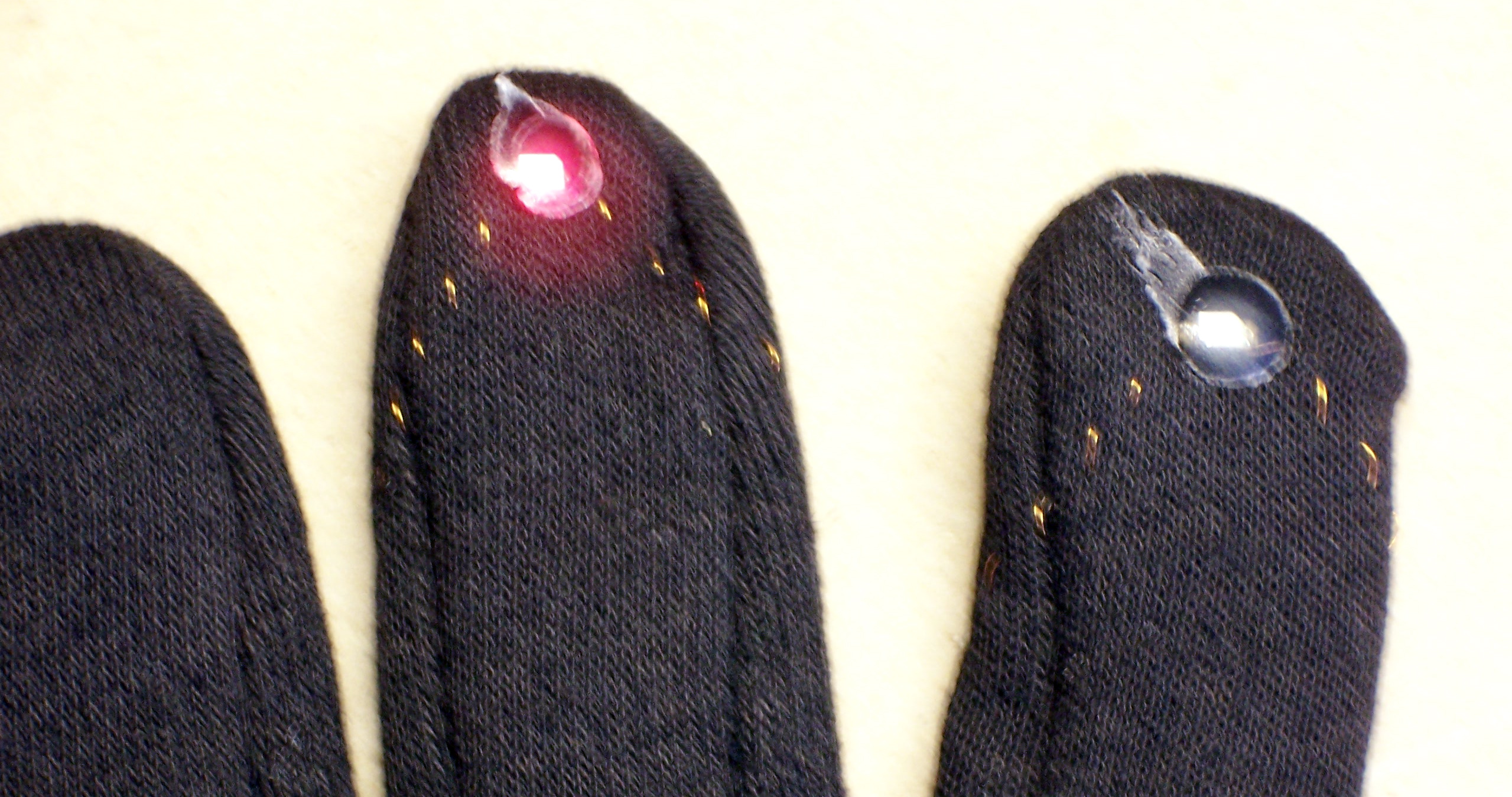
Due to the idiosyncracies of my digital camera, the green LED on the index finger doesn’t look very green in this picture, but it really is. It’s a lot dimmer than the red LED, though; and I’m not sure why that is. Before going beyond a prototype, I’d want to pick current-limiting resistors to more closely calibrate the brightness of the different LEDs.
I don’t have a translucent globe to use, but I borrowed a hemispherical Tupperware bowl from my friend Lawrence’s daughters. (Don’t ask my why the girls have their own set of Tupperware–I really don’t know.) It works well enough to demonstrate the idea:
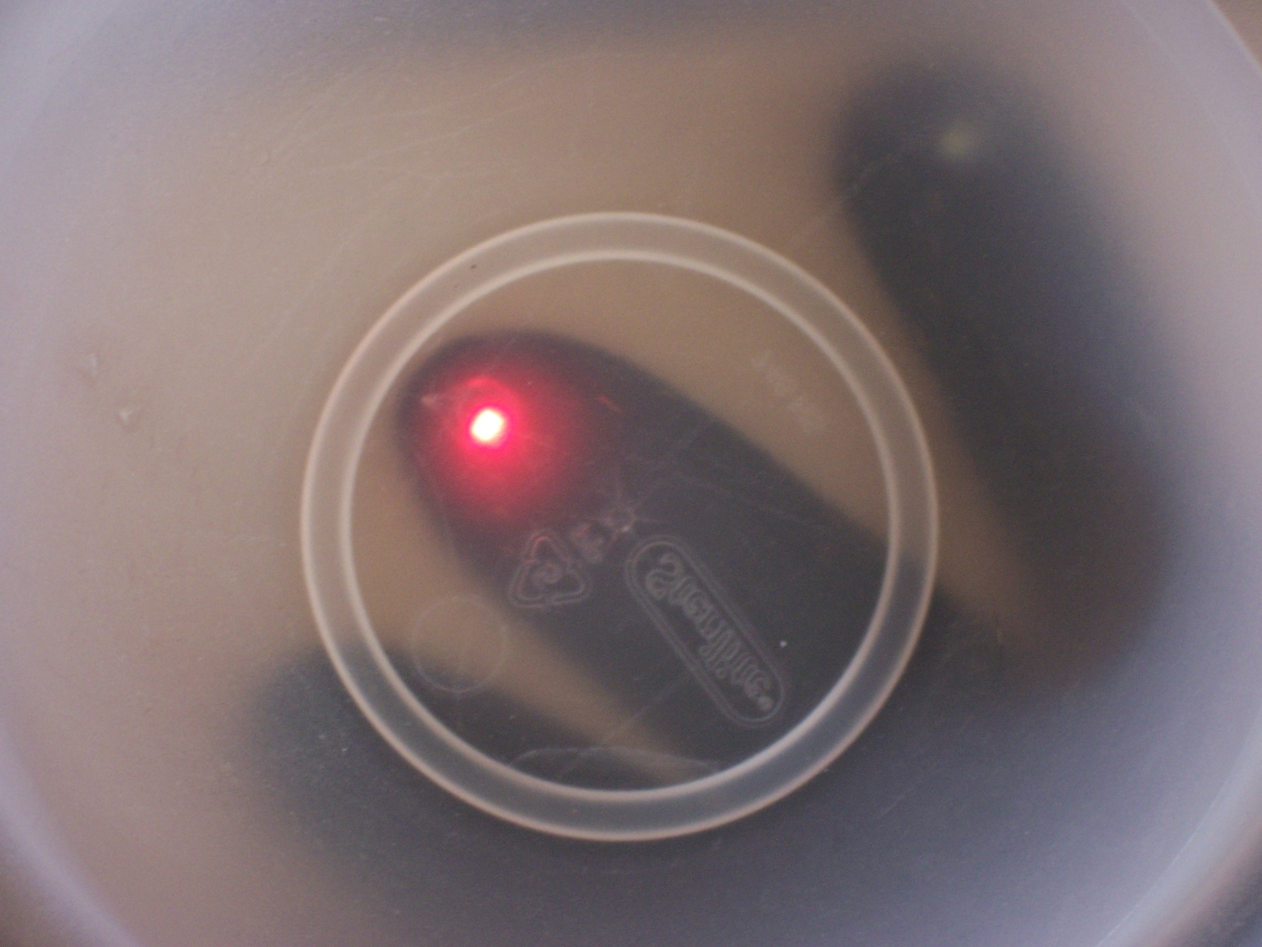
You can clearly see where the red LED is touching the bowl. Now all we need is a videocamera, some fancy software to track the lights, and an interface to a video synth. ![]()
Seriously, all of those things are Steve’s domain. I just wanted to see whether I could throw together a working glove, and I think this’ll do.
Oh–and when you want to shut it off, you take out the battery and drop it into the thumb.
“So I trimmed it a little closer and more evenly around the fingertips, for better fit and comfort.”
You know, I thought to myself the second I put the glove on, “boy! this is the most comfortable, well-fitting LED glove I’ve ever had the pleasure of wearing!” Thank you for your consummate sartorial professionalism.
This looks great. However, I’m having trouble finding a wire that i can thread the glove with. Is there a specific size i should buy? Did you use a needle to sow it?
Thank You.
Zaid, I’m not sure about the gauge of the wire I used, although if I could find it, I could measure it with calipers. Somewhere in the 30s. And yes, I did use a fairly large needle, and sewed it just like thread (although being more careful not to tangle it).
It was wire made for winding magnetic coils of some sort, for transformers or instrument pickups. If you like to salvage things, you could find a small transformer from inside a dead CRT monitor; or you might be able to use the 30-gauge wire from Radio Shack’s magnet wire assortment.
Also definitely check out the work of Leah Buechley, a pioneer in making wearable circuits. I know she has information somewhere on her site on the conductive thread she uses.
Thank you for the quick reply! Now that i know what i’m looking for, i can get right on it. Excuse me for my ignorance, I have not worked with electronics before; I have been trying to create an LED glove like yours so i can do some image processing. I found your post very informative and if you don’t mind i have a few more questions:
Would i need to calculate the amount of voltage i need, or should i find a battery holder like yours? (I need 6 LED lights on the glove, – one on the palm) Are resistors necessary?
What would be the best design for that many LEDs, series? parallel? a combination perhaps?
I have noticed that the lights get hot quickly, do i need to worry about that or would the glove be enough protection?
Thank you very much for you time Keith.
P.S The link to Leah Buechley was very useful.
Zaid, LEDs (almost) always need current-limiting series resistors. I knew I could get away without them because the battery I was using was very low capacity — it’s described as having a high “internal resistance” — that took the place of an external resistor, at least for a short-term demo. But that’s not necessarily how you want to do it for real.
What color LEDs are you using? Different colors have different voltage drops, and I can show you how to calculate the resistor you’ll want to use. For this application, if you’re using all the same color LEDs, I’d suggest one resistor and all the LEDs in parallel behind it. If different colors, probably a separate resistor for each.
The resistors will take care of the overheating problem, too.
Keith, the LEDs I’m using are all green with the following specs: 2.1V – 25mA – 6.3mcd. I have a battery pack that holds four AAA batteries; also, i can make a pack myself with AA batteries, however, i would prefer using the pack since there is a switch and is already pre-made.
I will follow your advice and use the parallel design with one external resistor. However, I’m not sure how to calculate the amount of resistance i need for the circuit to work as intended.
Thank You.
Zaid, the 4xAAA pack will be great for this — it’ll give you a lot longer life than the little coin cell I used.
Okay, let’s figure out the resistor. First we need the battery voltage. I’m going to assume you’ll be using NiMH rechargeables, both because you’ll be playing with this a lot and because they’re better for the environment. They’re nominally 1.2V per cell, although for this application they should still be quite usable when they’ve drained to 1.0V per cell. So you have a supply voltage range of 4.0 – 4.8V.
I don’t know how much electronics you know and how much you want to know, but the supply voltage is going to be split between your LED(s) and your resistor. Your LED specs say the LED will take 2.1V, so the remaining 1.9 to 2.7V (depending on battery charge) will fall across the resistor.
Now we want to calculate a resistor value that gives 25mA at 1.9 to 2.7V. Given that I (current) = V (voltage) / R (resistance), you can rewrite to get R = V/I. So
So a 108Ω resistor would be perfect when the NiMH cells are fully charged and a 76Ω resistor would be perfect when they’re a bit discharged. If you want to run the LEDs at the full 25mA, I’d compromise and use a widely-available 100Ω resistor.
That said, I’m guessing you won’t want the full 25mA / 6.3mcd. I think you’ll get lens flare on your videocamera at that brightness, and in my experience I think you’ll actually want something closer to 10mA. Assuming you can make sense of the equations above, I’ll leave those calculations as an exercise for the reader. Plus you can always get some different sized resistors in the 100 – 1000Ω range and just try them.