I went to Radio Shack yesterday for some patch cords and discovered three 3′ MIDI cables for $13. Score! Bought ‘em.
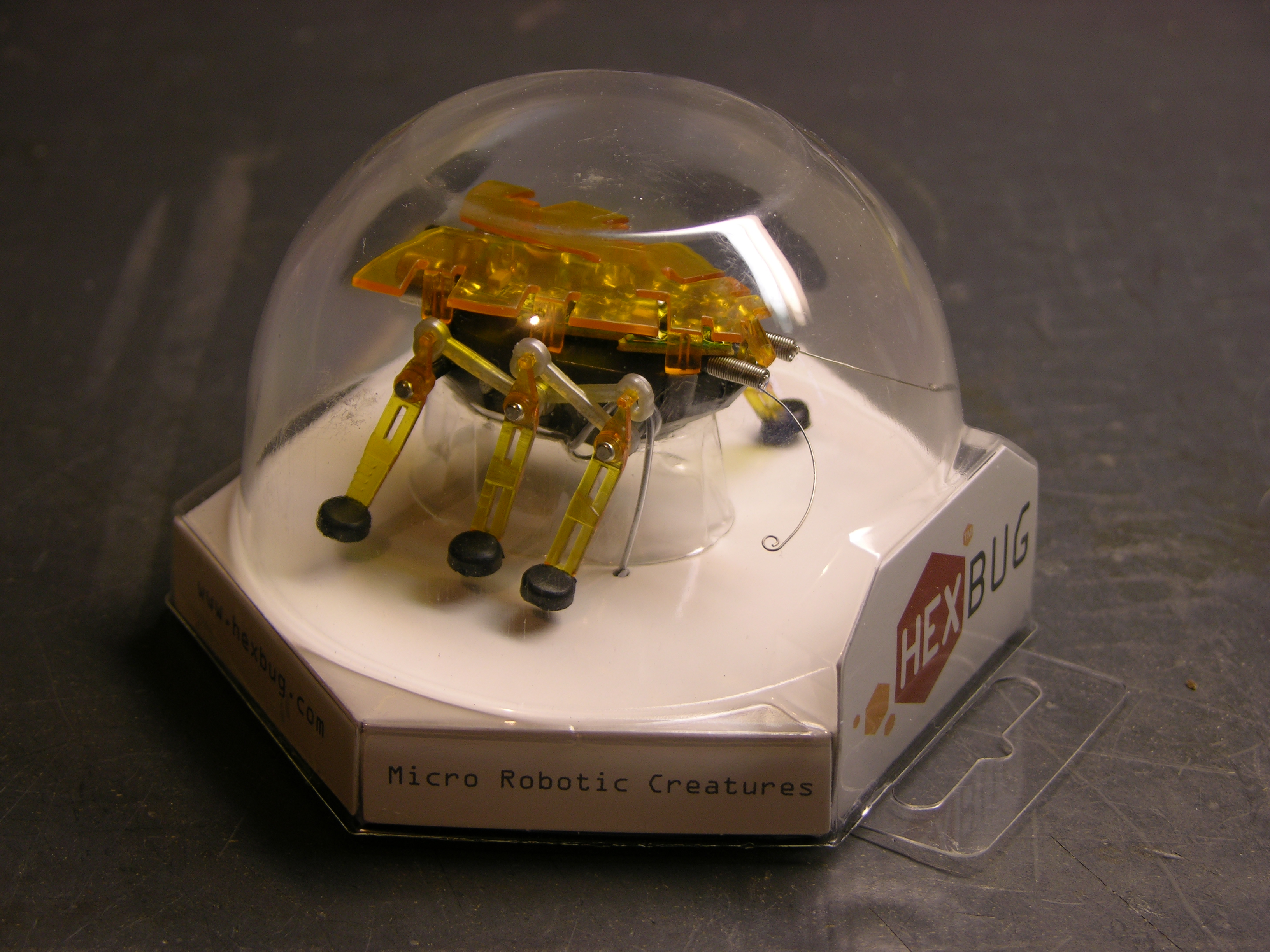
At the checkout counter, they have these cute little motorized bugs for $10.
I was afraid it’d be lame; but I played with it a bit. When its feelers hit something, it backs up and turns. It sure looked like two motors were being used to control the forward / reverse-turn behavior. Turns out I’m the one who’s lame for getting fooled; but we’ll get to that.
$10 was about my threshold for a bug with two motors and two touch-sensitive antennae. It’d take some tricky rewiring or maybe making a new circuit board, but it should be possible to make the bug a lot smarter. Plus I didn’t really care about the microphone and response to loud noise, and I figured that accounted for a lot of the circuit board, which I could disable or remove.
Plus it’s really compact. The body is only an inch wide and about an inch and three-quarters long; that makes it really cute.
Bought one. Took it apart today.
Pre-Operative Impressions
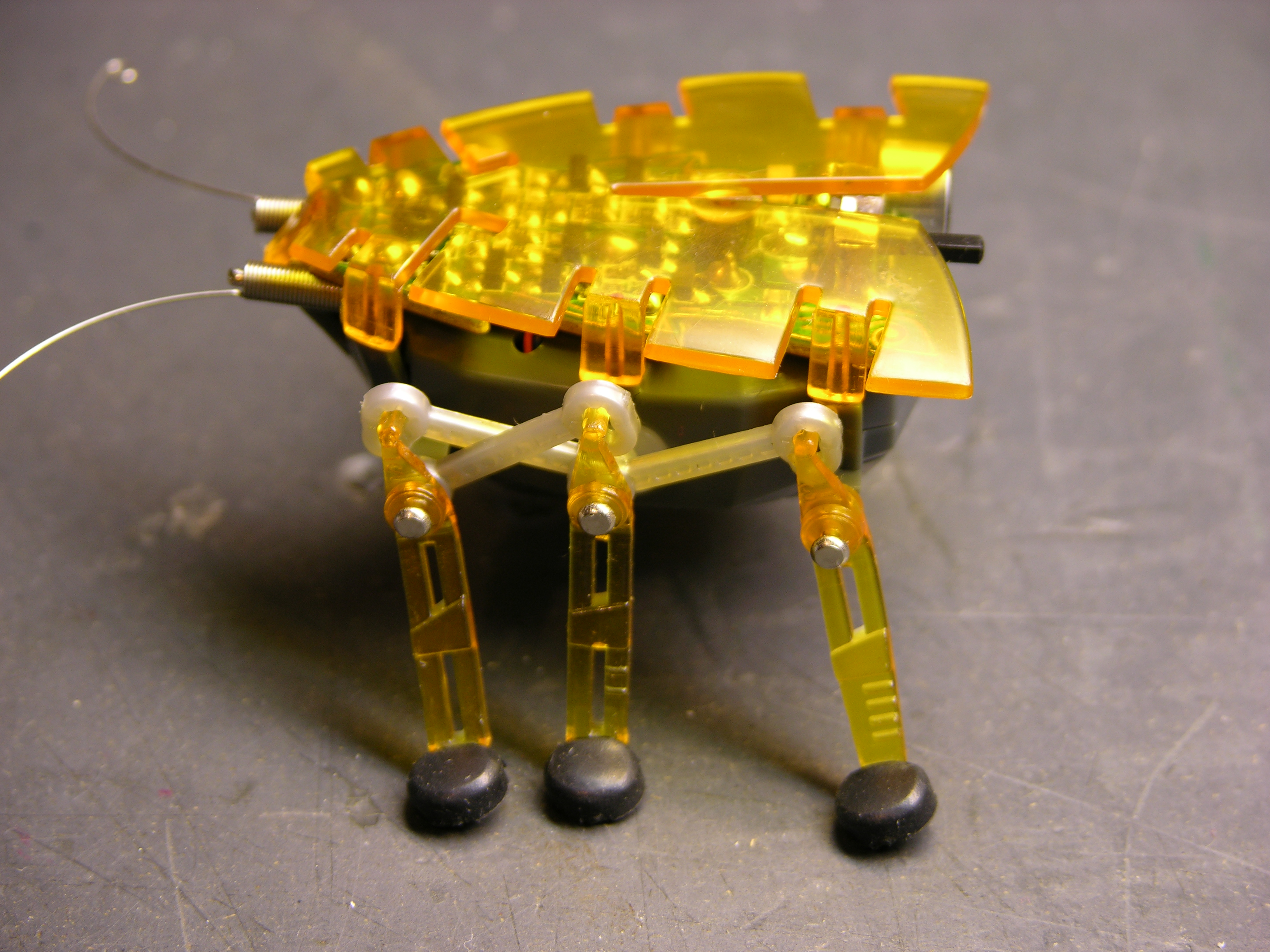
The Hexbug is what I call a faux walker — it doesn’t shift its balance to place its center of mass over alternating feet, and each side’s legs only have a single degree of freedom. It’s incapable of falling over, and it could just as well have treads or wheels. It’s still cute — I’m just being clear that I have no delusions about its level of sophistication. Except how many motors it has.
Each side’s legs are powered by a single rotating shaft, shown below. The linkages in the picture above transfer that motion. The front and rear legs move in sync, and the middle leg moves in the same direction but 180° out of phase.
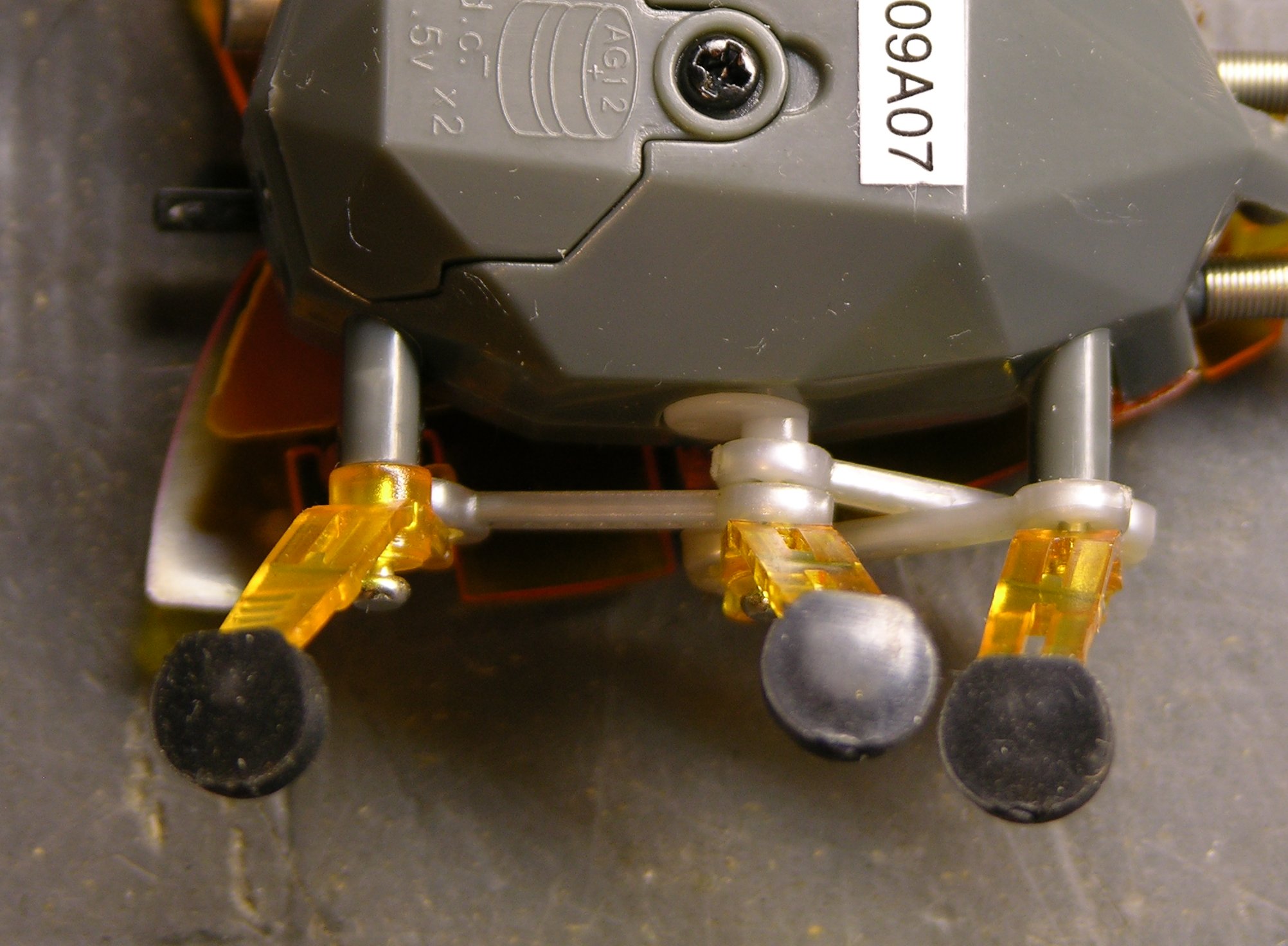
With the bug upside-down, you can see the rotating shaft coming out of the bug body, with an eccentric knob driving the linkages.
The outer legs’ axles are stationary, so the legs just swing back and forth. The middle leg’s axle is attached to the eccentric peg on the rotating shaft, causing the middle leg to move up and down while turning; this is how it lifts its foot to move without dragging.
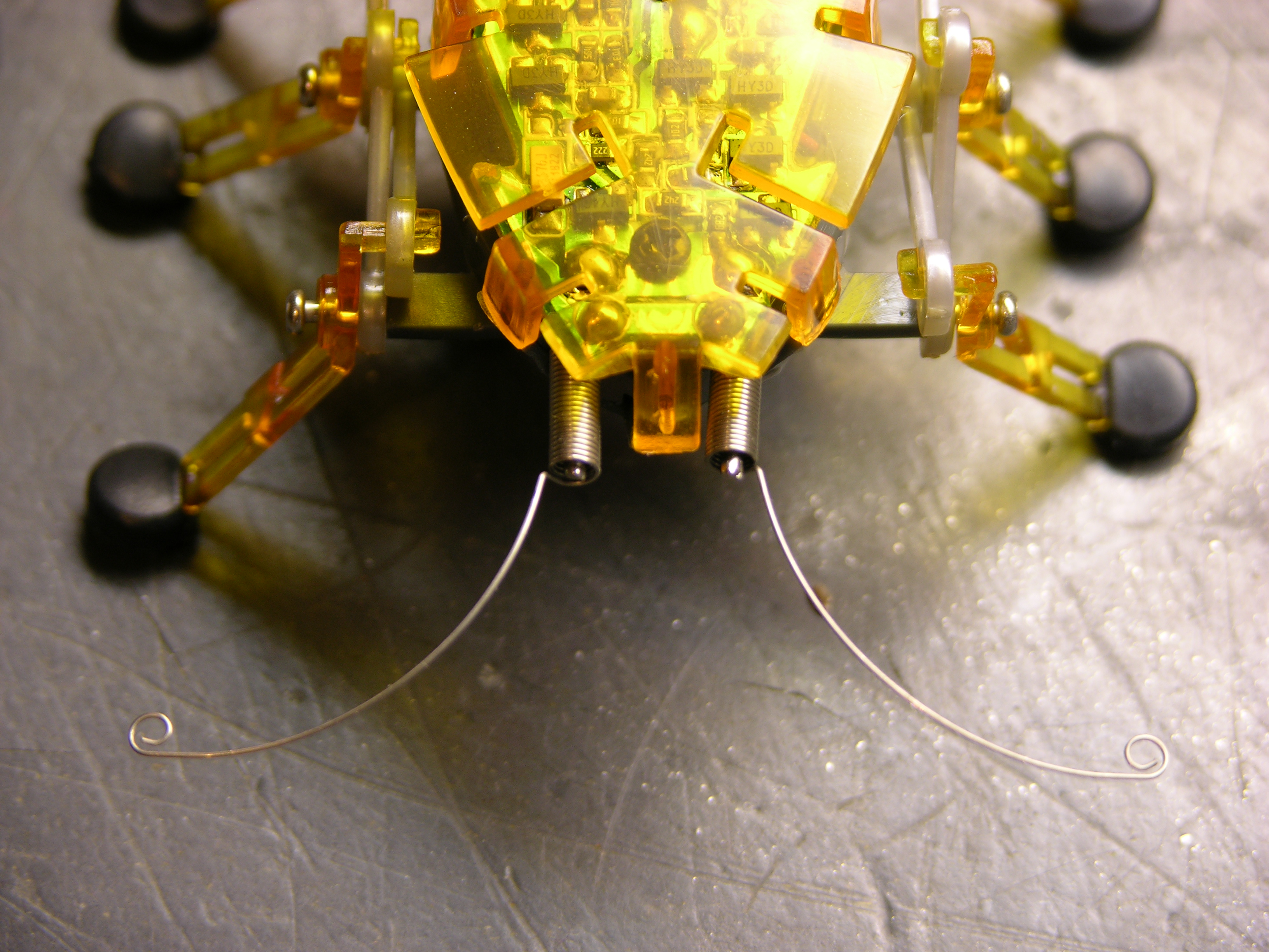
Finally, before beginning disassembly, the antennae are coiled springs positioned around stiff wire, with feelers protruding at the ends. When a feeler presses against something, the coil portion of the spring contacts the wire, closing a circuit and telling the bug to reverse and turn. These are actually more nicely done than other wire feelers I’ve seen — they do a really good job of retaining their shape and position.
Now to Operate . . .
The orange wing is press-fitted on, although more tightly than I expected. Each of the six side flaps that bend down, plus one on the front, continues in a peg pressed into a mating hole in the body. I put a flat screwdriver between the PCB and the wing and twisted to loosen each peg, being careful not to crush anything on the PCB in the process.
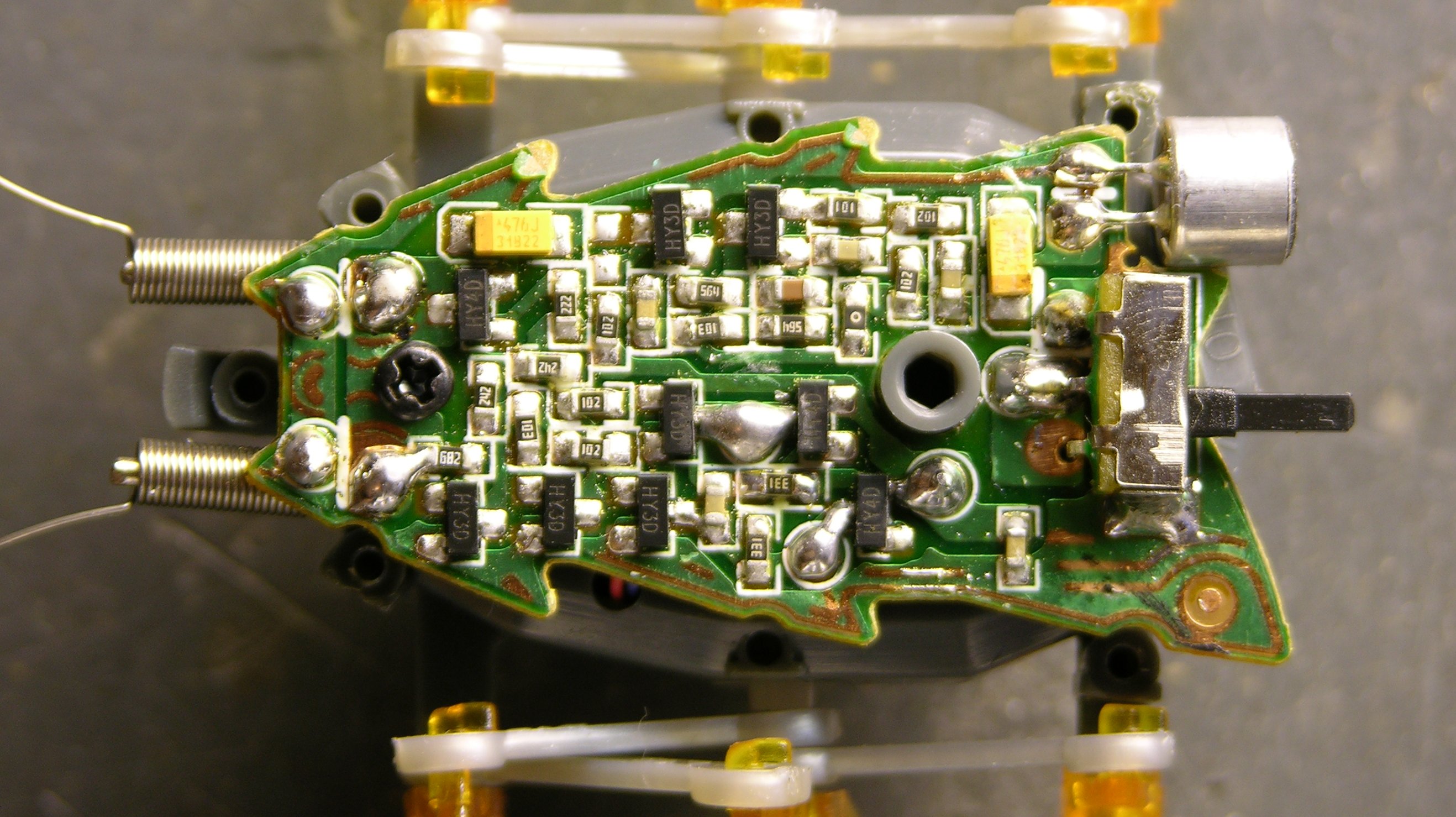
There’s the brain. I haven’t traced the circuit, but I can make a few observations. The solder blobs below and to the right of the grey standoff in the middle of the board are the battery connections, the blobs at the front are obviously the antennae connections, and the blobs in the center of the lower half of the board are the motor leads. Two leads. One motor.
The top of the board looks like it’s audio processing, running from the microphone in the back toward the antennae at the front (since a loud noise and an antenna hit perform the same function) and feeding into the motor drive on the lower half of the board.
Motor and Drivetrain
Removing the screw from the PCB and pressing in a latching tab at the back end of the bug (I did it with the batteries already removed, but this might not be necessary) allows the bug’s body to split open, revealing the motor and drivetrain. Motor. One motor.
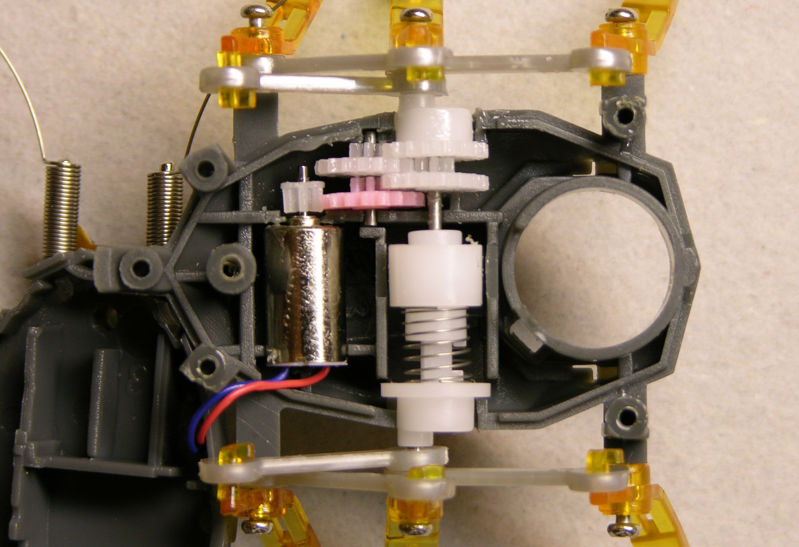
Look. It’s one motor.
Duh.
The motor leads aren’t very long, so the upper half of the bug is tucked under the front end of the lower half of the bug in this pic.
When the motor is turning “forward” and the white gear at the top of this picture (right-side legs) is moving with its upper teeth going forward, the coil spring at the center is being turned in the direction that makes it “unwind” and expand in length. This forces the cam at the bottom of this picture (left-side legs) to turn with.
When the white gear at the top is moving with its upper teeth going backward, the coil spring is being turned in the direction that winds it tighter, making it contract. This releases pressure against the bottom cam and causes the spring to slip against it instead of forcing the cam to turn.
What Next?
So now I don’t know what to do with this dumb bug.
- Be a good little consumer and let it wander around my desk until its batteries die or it falls off and gets crushed. Not my style.
- Mod it for two motors somehow — stick another motor in (hard!) or buy another bug, rip the left legs off both of them, glue their left sides together, and have a double-wide bug with two motors. But that’d require another $10 bug, and one $10 was the max I’d spend for a two-motor bug.
- Figure out something else cool to do with it. Dunno what.
OR
- Give it a smarter behavioral system that, within the capabilities of its lameness, emulates a two-motor bug.
The last one is actually kind of intriguing. Right now, when it hits an obstacle, it backs up enough to do about 90° of clockwise turn, regardless of which antenna made contact. So “reprogram” (rewire) the bug to discern which antenna was hit and turn 90° CW or 270° CW accordingly. Because it rotates about its left legs rather than its center, 270° CW is not the same as 90° CCW would be, but it’s as close as we can get.
With a tiny microcontroller on board, it could get more sophisticated yet, turning at other angles, and even doing quick reverses during normal forward travel in order to move in forward curves.
Thoughts?
I’d lean toward the latter – adding a microcontroller and hacking it to behave a little more intelligently.
Radio Shack fooled me several times as a kid. There was Armitron, a RS rebrand of a Tomy toy.. a fully articulable “robot” arm that ran on a single hobby motor and a masterwork of a transmission. I also had a “Robot Banker” that resembled an industrial robot arm and ran through a very convincing sequence of apparently multi-motored motions, again on a single motor. The first time I saw a description of an automaton, I immediately recognized what I had, but it wasn’t until later that I truly appreciated the cleverness of the engineers who created these things.
As for the bug, it might make an interesting BEAM subject, though mechanical efficiency is clearly a weak point.
25 or so years ago, RS had a robotic arm. It had up/down; rotate CW/CCW; clasp; an elbow; and a wrist that could also rotate. It also had exactly one motor!! I was, and still am, in awe of the designer(s) who conceived of the gear-trains!
the_captn
Matt, Neil, you hit on a good point when you reference the amazing engineering that went into making some of these things run off a single motor, and I thought about expressing appreciation for that in my post.
Heck, I can’t even visualize the behavior of the connecting rods in this bug; I have to trace it out step by step, waving my hands in the air and looking daft. I remember bump-and-back cars from my childhood with a single front wheel whose axle had one end mounted on a pivot and one end loose, so the idler wheel would swing from straight to turning when the car backed up. Whoever first thought that up was, in my opinion, a genius.
I never had a Furby, but I vaguely remember that robotics hackers were sorely disappointed when they opened it up and found far fewer motors than they expected. I think the whole thing ran off a single motor and an astonishingly clever set of cams. That meant that programming new behaviors into it relied on running the motor back and forth through a particular range of motion to trigger the cam back and forth, rather than individually controlling separate motors as they had hoped.
I was wondering if there was a way to hack or modify it to make it aware of edges. That one feature would make it a much better product in my opinion. As is it is a glorified 1 function RC toy that uses clapping instead of a remote to make to go back and to the left (or right which ever).
I am not skill with the electronics, but that one feature (cliff avoidance) would be good.
Thomas, it should be fairly easy to add a down-facing optoreflector for cliff avoidance. If you have in mind simply keeping the current back-and-left behavior, you could probably add a tiny daughterboard and wire it in parallel with the existing whiskers. If you’re thinking of building a new board entirely to house a microcontroller, it’d be even easier to integrate.
I wish that I had seen this website BEFORE buying one of these. I had left robotics for about two years to pursue astronomy. I would occasionaly glance at SERVO magazine when Night sky or ASTRONOMY were not available. When I saw the ad for the Hexbug (and @ $10.) I thought” Hey…maybe I should get back into robotics!). I think I hear one of telescopes calling me.
The only thing I wanted to do with mine was to locate low current pulses on the PCB that I could use to trigger AMT LEDS. These firing under the plastic “wings” would make it more interesting on my office floor after dark. Too much work is my excuse for not having pursued it, yet.