When I want to know what value current-limiting resistor to use with an LED, the easiest thing to do is assume 5V supply / 15-20mA / old-school LED / 220-330Ω resistor, like we all learned from Forrest Mims in the 70s and 80s.
And then I tweak the resistor until the LED is as bright as I like, by trial and error.
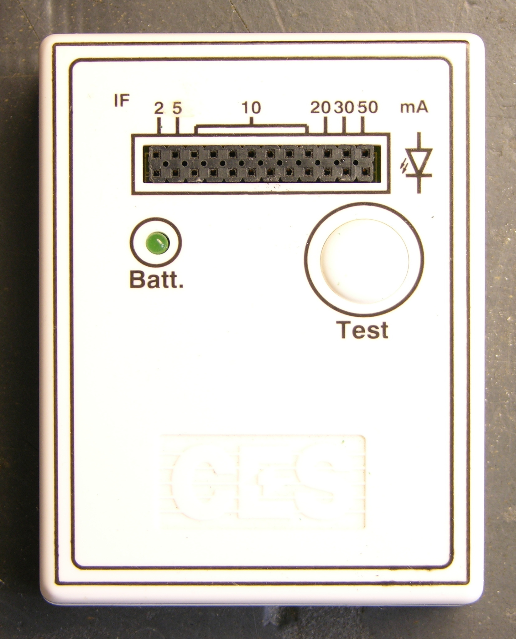
Oh, most of the time I use my LED tester to estimate the current I need for the brightness I like. At $6-10, it’s indispensible. Also double-checks anode/cathode pinning and tells me if an LED is burned out.
But running on a 7.2V supply (NiMH “9V” battery) with fixed current-limiting resistors designed for a 9V supply and low-forward-drop LEDs, it’s not really representative of what’s going to happen when I put a newer-chemistry LED with a 3.5-4V drop into my 5V circuit. So it’s back to trial and error.
I want a microcontroller-based LED tester/calculator that:
- has a socket for the LED
- has controls to set the target-circuit supply voltage
- has a current knob to turn until the LED is at a brightness I like
- displays on an LCD the target circuit supply voltage, the LED voltage drop, the LED current, and the value of resistor to achieve that current with that supply voltage
(That is, all the facts about the LED I’m testing, and the resistor value I need to use in the target circuit) - is about the size of my existing LED tester
Note that the tester need not be running at the target circuit’s voltage; we can calculate resistor values for arbitrary voltages once we know the desired LED current. It does need to have a higher supply voltage than the forward drop of new-fangled LEDs, and I’m inclined to run it on a 9V for compactness and simplicity.
I’ve been kicking this around for quite a while, and I’d really like to make one. And publish the plans and code for DIYers and make circuit boards and kits for kitbuilders.
Is that the right feature set? I personally never put LEDs in series, but should the tester be able to calculate for that anyway? What else?
Keith,
While your LED tester is a great project as-is, the goals for the advanced unit are even better. I agree with you about using 9 volts.
Please consider proposing an article about this to NUTS AND VOLTS magazine. If they are not interested, I am and will be glad to publish the plans for your present unit in THE CITIZEN SCIENTIST ( http://www.sas.org/tcs ) which I edit.
Forrest M. Mims III
Keith,
Consider a current source made with a transistor. The uC could read the current applied and the voltage drop on the LED. With these two parameters you could calculate the serries resistor needed given the supply voltage. You could have the uC display the resistor value as the pot is adjusted if you knew what the desired supply was.
I show a current source made from two transistors at the following link. You could use a simpler version for this applicaiton.
http://www.uchobby.com/index.php/2006/11/12/current-limited-pc-power/
Keith,
Instead of using a uC you could use a bench DVM as a display. Output the current as a voltage that is read by the DVM. The tester circuit could be very simple, just a small box with connections for the LEDs and a knob. The current could be output 1:1 (1 volt=1 amp) and a switch could select between current and diode voltage drop.
Keith,
You might also add a photo detector to measure the brightness of the LED with the uC and get a measure of relative brightness. Along with voltage drop and current you could find efficency. One issue would be calibrating the photo detector. I would like to know of a good way to do this. Perhaps a diode with known specs would work for this. You could also plot light output vrs current and find the efficent sweet spot for the LED.
Hmmmm, I am thinking a microcontroller with a A/D can do what you want, is it evil to change the User-interface to use 2 buttons instead, one for brighter, and another for dimmer? And then only have one LED socket?
The circuit can start in “dimmest” first, and then use the 2 buttons to adjust brightness up/down as desired.
When the brightness buttons are left un-touched for say 5 seconds, the microcontroller can spit out your answer directly to your USB port, serial port connected to your PC and display there.
But that’s not simple enough, the microcontroller should give a read-out on the LED under test or via 8 LEDs arranged in a binary-code? I hate to complicate it with a 7-segment display, because you need at least 3 digits, so maybe a USB port to your PC is the solution? The big advantage to a solution that runs off your USB port is that we can give resistor values for any power supply in a tiny GUI.