During the installation of “Organic Energy Cloud”, right after one of my fly wires turned bright red and dripped off the breadboard, I stopped being able to upload programs to the Arduino. As it was five minutes before the gallery opening, I didn’t want to take the time to replace the Arduino with a spare (that I’d had the foresight to bring along); and the Arduino was still operating with the last program I had loaded, which fortunately was sending a random twinkling pattern to the LEDs.
So I left it be and made a mental note to check it out later. Since the ATmega was still working but I had no communication with the board, I already had a guess that the FTDI FT232RL USB-serial chip was burned out. And I happened to have one on hand that I had ordered for testing LED puck USB control — which has been waiting for a year and can afford to wait a little longer.
Diagnostics
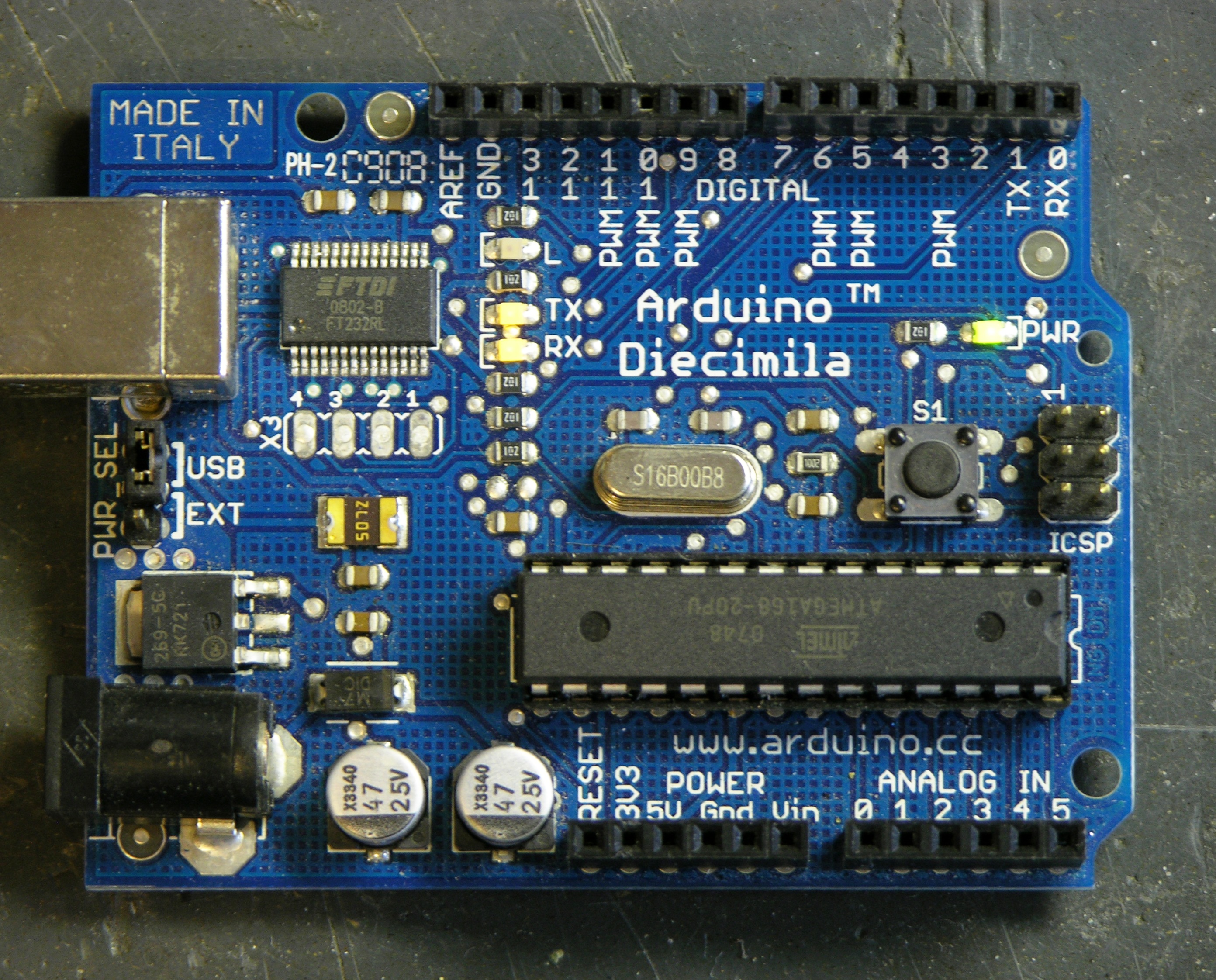
I hooked it up this morning and found that the TX and RX LEDs stay on solid (which my CoolPix doesn’t capture well) — not a good sign.
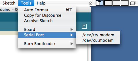
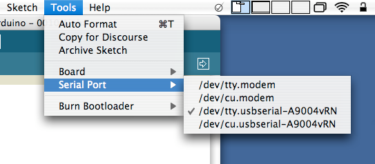
And the IDE’s serial port selection menu doesn’t list the USB serial connection as an option, further confirmation that the FTDI chip is toasty.
Removal
Removing SMT chips would be a great job for a hot air pencil. Since I don’t have one, I blobbed solder across all the leads on one side, then heated the solder mass with the iron while gently prying up that edge of the chip. It came up quickly and with little resistance, and I repeated the trick on the other side, then mopped up the excess solder with solder wick and brushed off the inevitable flux with rubbing alcohol.
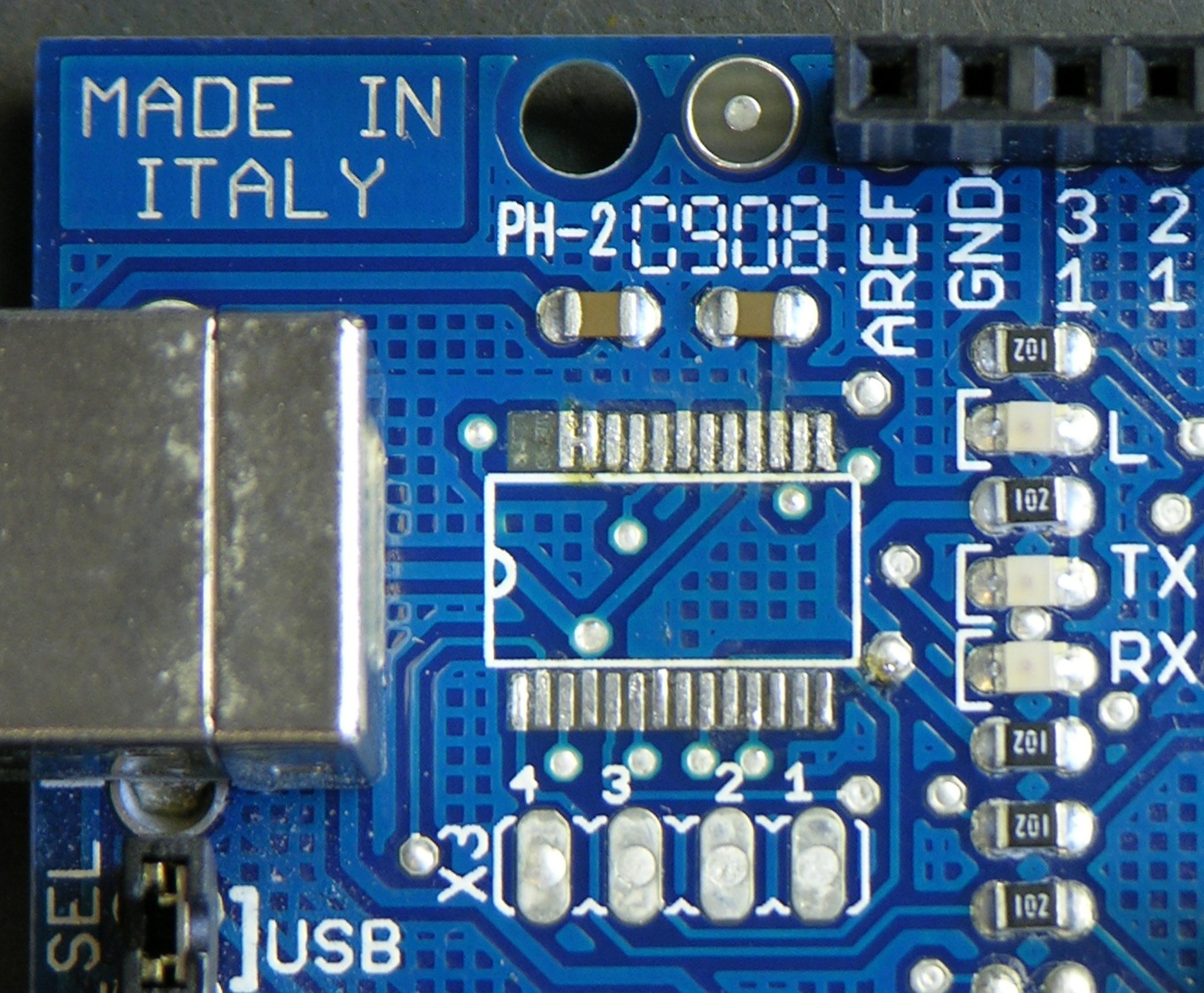
I pulled the pads for pins 27 and 28 completely off the board, but they were unconnected and are for an optional 12MHz external oscillator not used in this design. I also noted the bridge between pads 25 and 26, but it appears to be by design — the pins are both tied to ground anyway, 25 being AGND and 26 being TEST that must be tied to ground for normal operation.
Replacement
I tried using the blob-and-drag method to solder the new chip in place, but ended up using the SparkFun blob-and-wick method instead.
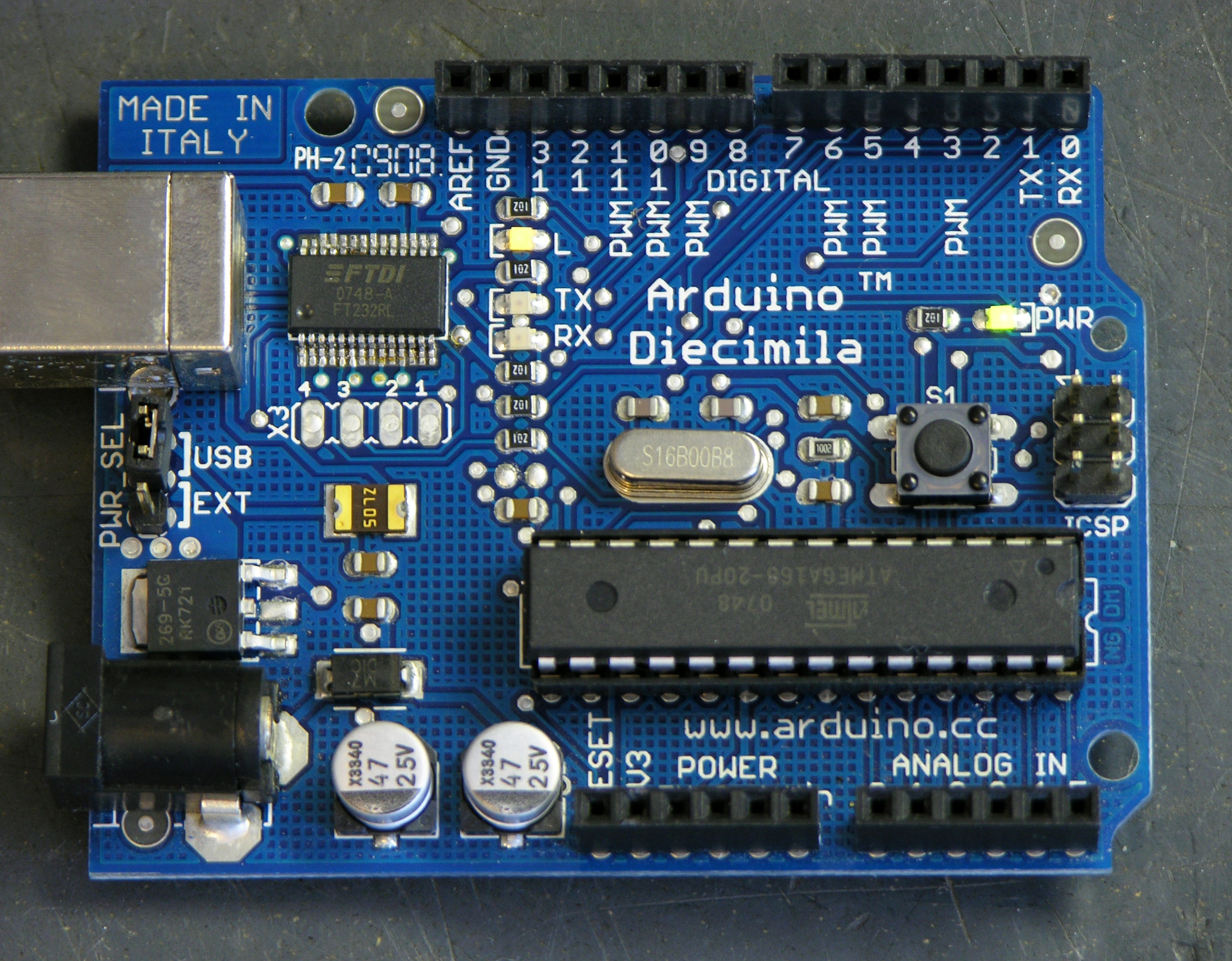
After cleaning the flux again, the resulting board looks pretty reasonable (although I managed to get the chip on crooked, dang it). And the serial lights aren’t solid any more,
and the board now shows up in the list of connection, and I can download programs to it again. Hoo-rah!
From experience, I can tell you that you did it the hard way.
If you are certain the SMT part you are removing is the bad one and you are not going to use it again then you take some fine diagonal cutters, or maybe a dremel tool if you have a steady hand, and cut each lead as close as you can to the body.
Then the IC (the black part) will just come loose and you will have a bunch of little leads connected to pads. They are very easy to remove without damaging the board by grabbing the loose part with tweezers and heating up the pad. The mass of the metal is small each one comes off easily.
Hi, MikeS!
I considered cutting the leads off and sweeping the stubs off the board with the iron. But I wasn’t 100% certain that was the bad part and I wouldn’t want to reuse it; and the leads are small enough, it would have been tricky cutting them off with diagonal cutters, and I don’t trust my aim with a Dremel.
Plus this turned out to be really the easy way. I had each side of the chip off the board in about half a minute, and I’m sure I would have spent longer than that cleaning up the chaff. So this approach did work well for me, for this chip on this board.
I used this chip a while back on a simple board for a customer. This was my first foray into the SMT world and it wasn’t as painful as I thought. =)
The technique for mounting new chips that worked best for me was to simply rely on the solder mask of the PCB for the weld. I added a small amount of paste flux to the chip legs (which also helped hold it in place on the PCB) and heated the legs briefly with a clean, small-tipped soldering iron. This resulted in a very neat soldering job.
William — there was enough solder on the factory board for you to get a good joint with just flux and heat? That’s pretty slick!
Did you have any trouble with the IC rocking as you soldered the individual feet down? I had difficulty with that when I tried your method on a board I had tinned by hand.
Know where I can get a small amount of solder paste at a reasonable price without exorbitant shipping? I’d really like to try some reflow techniques, maybe buy or build a hot air pencil, and I think solder paste is the way to go. I’m assuming I’d need a syringe, as I don’t really want to have to dab it on with a toothpick?
The problem with solder paste is that most of it has a “use by” date on it, and using it after that can result in poor/faulty joints. Since it’s relatively expensive, it’s a shame to have to throw it out, but that may be the best option.
Back when I was doing SMT by hand professionally (back in the early 1980s), we were putting 144 and 168 QFPs onto circuit boards. It helps to have a soldering iron that you’ve special ground the tip to a very sharp point (This requires frequent regrinding, since the tips dissolve slowly in the solder!). Also, a 40x stereo-zoom microscope helps, too. We used very tiny solder, rather than solder paste back then.
And, yes, it was as tedious as could be! I was luck to do a couple of chips per day. I found my best time was early afternoon (e.g., when I was least shaky).
Dave
Dave, I have a couple of nice sharp tips for my Weller and finer gauge solder than I’ve seen any of my friends use, and I actually rather enjoy hand-soldering fine-pitch SMTs. But there’s some appeal to the idea of using surface tension to “spring” components into perfect alignment.
Keith,
I didn’t have trouble with the IC rocking, though these PCBs were professionally fabbed (ExpressPCB in this case) with a really nice solder mask.
Hi Keith,
You were asking about cheap solder paste. I use this:
http://www.dealextreme.com/details.dx/sku.7952
And this is good too:
http://www.dealextreme.com/details.dx/sku.25919
Thanks for the article!
CapnKernel, thanks for the links! I see on your blog that you’re using some other interesting great deals from DealExtreme — worth a look for anyone who likes these kinds of projects.
Shortly after getting my Arduino i was playing with some DC motors and was powering the device through the USB->serial cable. It turns out this wasn’t the best idea and after a couple hours i was doing something and attached a motor mistakenly without a resistor when I should have had one. The result was burning ozone and a super hot FTDI chip. Luckily the program was still running so I guessed it was just the USB chip that failed.
I ordered a new chip from sparkfun for only $3.95 (shipping was just as much).
Rather than waiting for the new one to come I decided in a fit of activity that the old one should be removed. With a bit of prying and desoldering it was removed. During the extraction two of the wires in the board itself got pulled up.
After a week or so the new chip arrived in the mail. I started to prep the area and fix the pulled up wires and found my old radio shack soldering iron just not up to the task. After a trip to Frys I had in hand some 60/40 solder, Rosin Flux and a new Elenco SL-540 soldering iron.
After getting the new gear it was a much easier task. I dropped a gob of flux on the pulled up wires and pushed them in to place. I dripped some solder blobs on the contacts in the corner and attached the chip. After that i just wicked away the excess using a braided wire and used a tiny bit of solder and lots of flux to get the rest of the contacts down.
Here’s the finished result: http://services.nirvanix.com/NirvanixDrive/public/email/DSC09394.JPG
http://services.nirvanix.com/NirvanixDrive/public/email/DSC09395.JPG
I was terrified of plugging it in but it turns out it works perfectly, it just looks horrible.
Thanks so much for the blog. You encouraged me to give it a try and it worked out great!