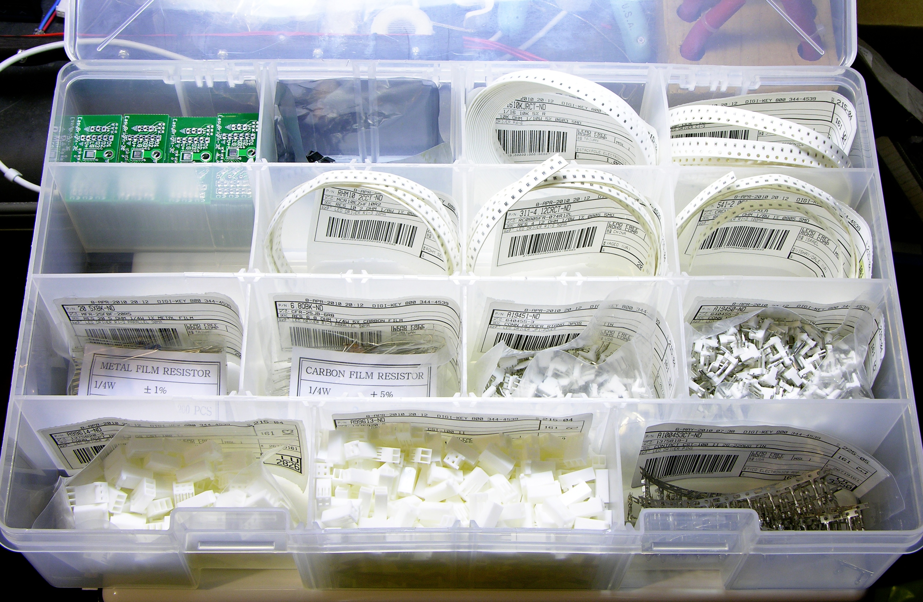
Last week while watching Mannequin (a very young and fresh Kim Cattrall, a goofy plot, and music by Starship — what could be better? okay, if it had John Cusack and were set in Shermer, Illinois, yes, that would be better) I split all the EasyBright components into a parts bin for easy access and portability.
Saturday afternoon I put together the first sample.
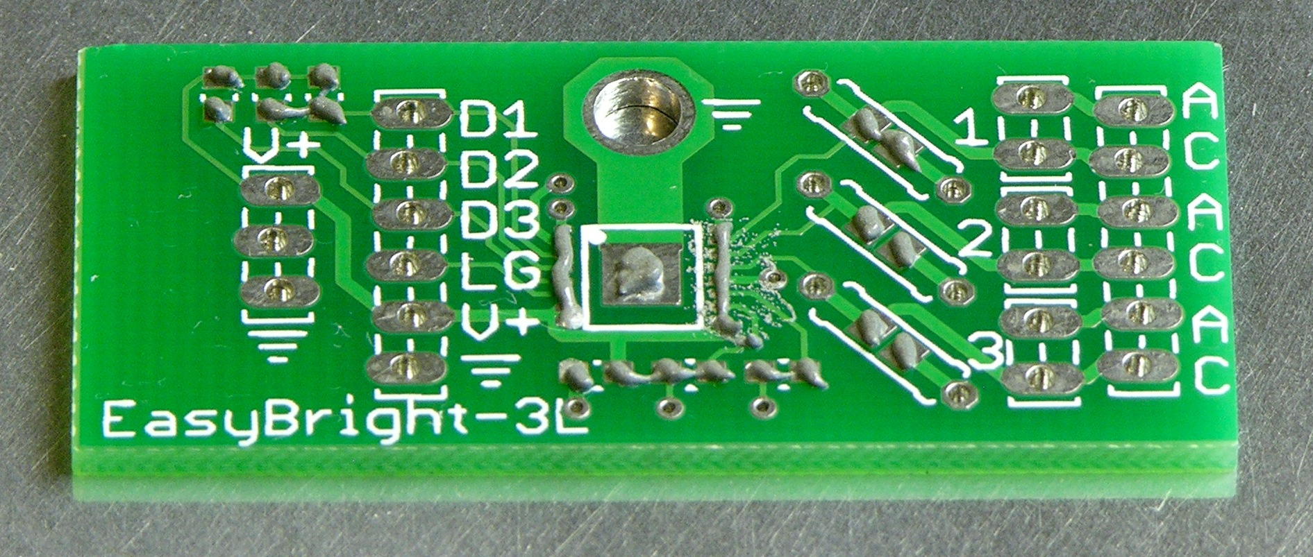
This is waaaaaay too much solder paste for 0603 parts and 1/40″ IC pin spacing. I had to remove several solder bridges from the IC, and the passives had solder mounds instead of fillets. I took the picture specifically to record how much paste I used so I could adjust on the second attempt.
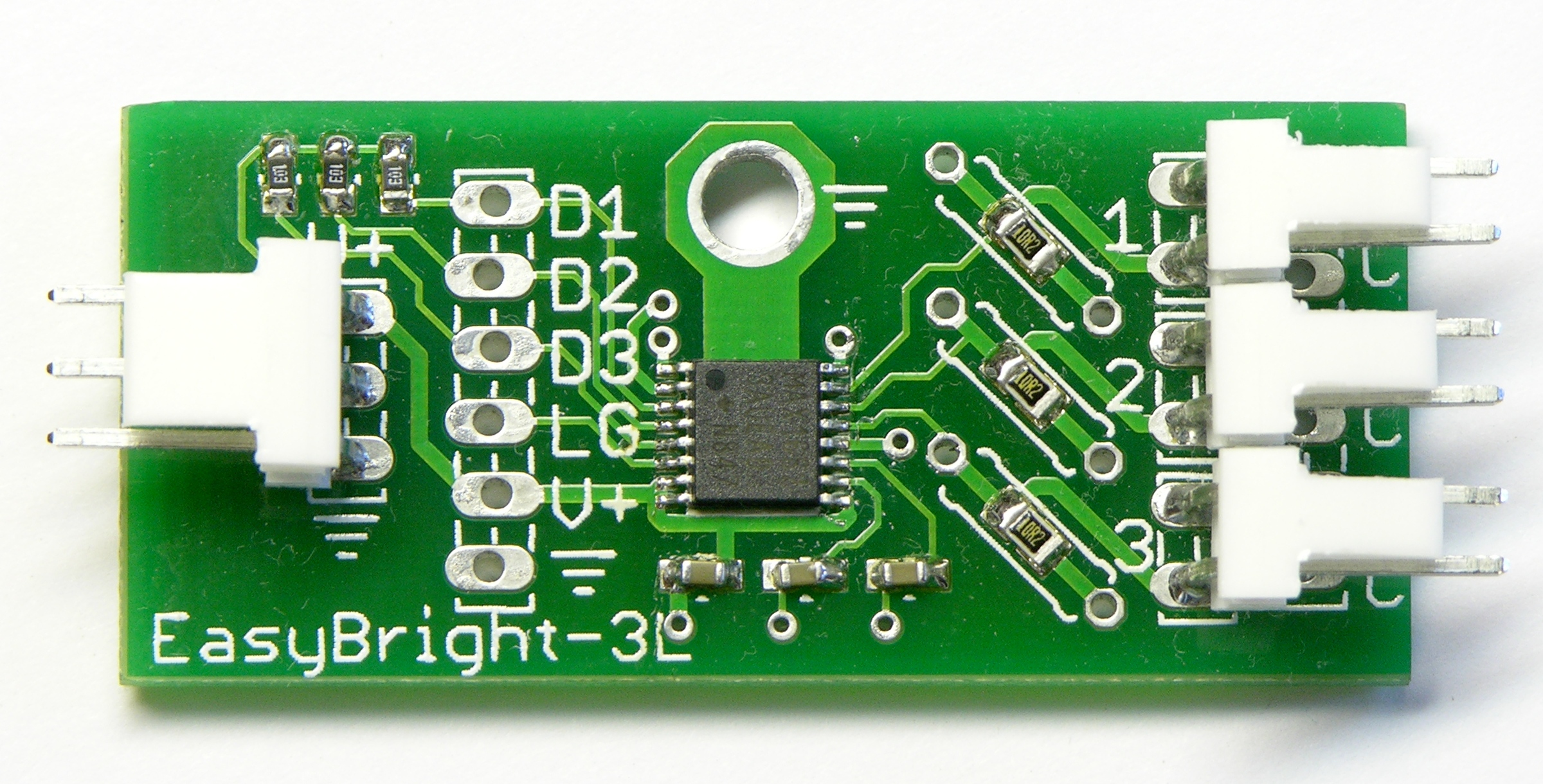
Here’s the cleaned-up board, front side.
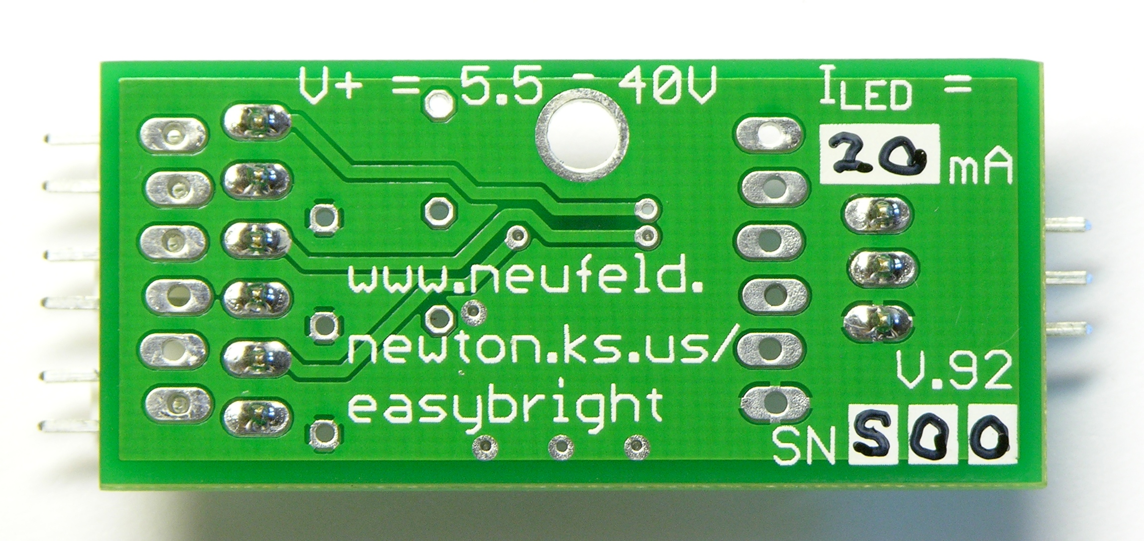
Back side, with hand-written labels for the current rating and the serial number (S00). The “permanent” marker comes off easily with rubbing alcohol — I need to get some clear nail polish to seal it in.
Changes
Even before assembly, I had made notes about (and started implementing) things to fix whenever I print the next boards:
- Change the IC’s ground connection from a via outside the IC footprint to a trace going straight in to the heatsink pad. I had routed that connection before I confirmed with Maxim that the pad is okay to connect to ground — it’s just not okay to be the only ground — and then forgot to go back and change it. Removing that via gives me a little more room to route the bottom-side LED power traces cleanly, and also:
- Increase the pad size on the optional through-hole current-sense resistors. This, believe it or not, is EAGLE’s default pad size, and I think it’d be challenging to solder without a good, narrow-tipped iron.
- Increase the trace isolation on the solder-side ground pour. There’s no reason to have it that close to the pads.
- More subtle, I spaced the 2-pin connector pads an extra .02″ apart to see whether I could get the connectors to friction-fit for ease while soldering. They don’t quite. Either change the library footprint to space the pads a little further apart or just get used to pinching the leads together before stuffing the parts and soldering, which works better than I had expected.
I’m still delighted!
What method did you use for soldering? I’m guessing you just used a regular soldering iron as I’m sure you would have mentioned if you were using a hotplate, oven or hot air.
Rob, for me solder paste == hotplate unless I specifically mention that I’m using my new hot-air pencil (as I will do when soldering the FTDI chip onto my x0xb0x, more to try it out than because it’s too hard to solder by hand).
What is the reason that you have all the pads offset a little bit to the left and right? See purple line here: http://localhostr.com/files/b0c754/DSCN6962_mid.jpg
Congrats on getting the boards and getting started making drivers!
Shame about the $50 charge due to the resistor wiring issue, though.
Anyway, have you considered using stencil? I’ve been using solderpaste in a syringe myself, and found it tedious (plus it tended to separate… but then I was using cheap chinese paste). http://www.smtstencil.co.uk/ is pretty cheap ($21 for a 21x22cm stencil), and stencilling onto small boards looks much quicker (plus it’s much more repeatable). I think Sparkfun did a tutorial on it.
Asm, I’m definitely interested in stenciling in the long term. I didn’t order one yet because
I knew I could ramp things up faster with the syringe and then switch
I want to get feedback on the design and be sure the board layout is finalized before ordering a stencil
I have the impression it’s easier to stencil a slightly larger area than such a small one but I don’t really want to have to depanelize the boards myself
I’d be particularly interested in hearing from someone with experience stenciling tiny boards like this — and I should probably review the SparkFun tutorial.
Patrick, the alternating-offset header pads are my copy of SparkFun’s “locking connector” idea — it allows the connectors to stay in place by friction when you turn the board upside down to solder, without making the through-holes too small for good solder flow. Huge credit to Pete Lewis at SparkFun for coming up with the idea — it’s fantastic and it really works!
Hey Keith, how do I get my hands on the EasyBright then? The LED calculator looks like something I would want as well!