I have some ideas for things I’d like to do with really bright LEDs, and Philips has the brightest that are readily available to hobbyists right now. They’re brand-named Luxeon, and they’re manufactured and marketed by a wholly-owned company named Lumileds.
A typical 5mm LED can pass 15-20mA of current. Lumileds’ first product to market was the Luxeon I, which (when properly heatsinked) can pass 350mA of current; their more recent LEDs can handle even more. An LED’s power-handling capacity is mainly limited by heat, and Lumileds has found a way to bond the LED die to a heatsink that extends out the base of the package, for further external heatsinking. This allows their LEDs to pass vastly more current without burning out.
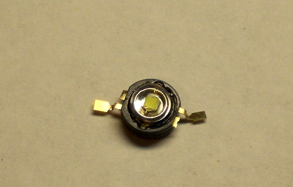
A while back, I found a good price on some Luxeon I emitters (just the LED; Luxeons are also available premounted on a star-shaped base) on eBay and bought a small batch to experiment with. Because I knew that external heatsinking was required to drive them at anywhere near their capacity, I set them aside until I’d have an opportunity to build a test PCB.
Design Considerations
Two documents from Lumileds proved particularly helpful:
The LED’s heatsink (“slug”) is not electrically neutral, and must not be connected to either the anode or cathode. It must not be soldered, and should be joined to a heatsink with thermal grease or epoxy. So a carrier PCB should have a large copper plane for the slug, and the electrical connections for the anode and cathode should interrupt the plane as little as possible.
The Thermal Design Guide goes on to say that standard PCB substrates don’t dissipate heat well enough for Luxeons, and aluminum metal-core PCBs are recommended. Each LED should ideally have 36 in2 of heatsink, and an LED with only 1 in2 of heatsink can be operated at room temperature but may reach up to 70°C.
Whatever. I have plain old PCB, and it’s going to have to be good enough to test with.
The Electrical Drive document recommends powering the LEDs with a constant-current source. LEDs are commonly powered with a series current-limiting resistor; but at the high operating current of Luxeon LEDs, a great deal of power is wasted (and converted to heat) in a series resistor. Constant-current drivers place a very low-valued “sense resistor” in series with the LED, then measure the voltage drop across the sense resistor to feed back and control the supplied power.
Whatever. I have a plain old resistor, and it’s going to have to be good enough to test with.
Resistor Selection
This was actually a pretty quick calculation, and I did it in my head because I don’t mind being a little sloppy with this test rig, but it’s good to run through the details anyway.
The Thermal Guide recommends no more than 100mA without good heatsinking, but I figured I’d shoot for 200mA (out of 350mA when properly heatsinked) and see what happened.
The voltage drop across the resistor (VR) is equal to the supply voltage (VS) minus the diode’s voltage drop (VD):
VR = VS – VD
With a 5V supply and approximately 3V drop across the diode, we get
VR = 5V – 3V = 2V
For a target current of 200mA:
R = VR / I
= 2V / .2A = 10Ω
Then the power-handling capacity of the resistor needs to be:
P = I V
= .2A * 2V = .4W
So I pulled a 10Ω half-watt resistor out of my parts bin and was ready to go.
Constructing a Test PCB
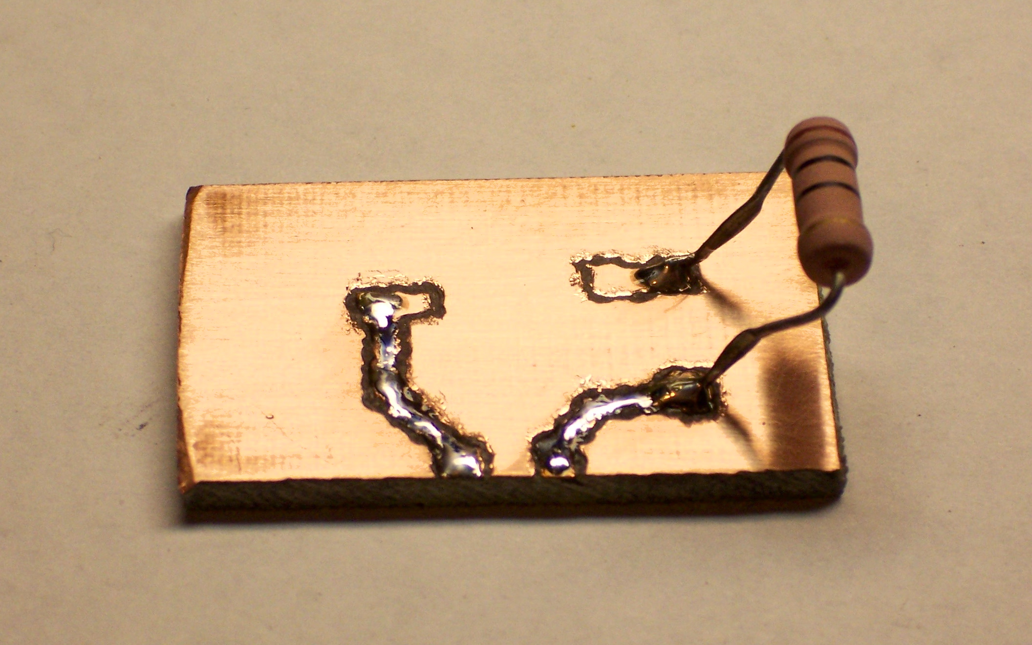
I didn’t feel like etching a board, and I don’t have a milling machine built yet, so I went the scabby route and hand-milled a board with a rotary tool.
First I traced the LED’s outline onto a scrap of PCB (a little over 1 inch square), marked pads to surface-solder a resistor and power connectors, and drew in connecting traces.
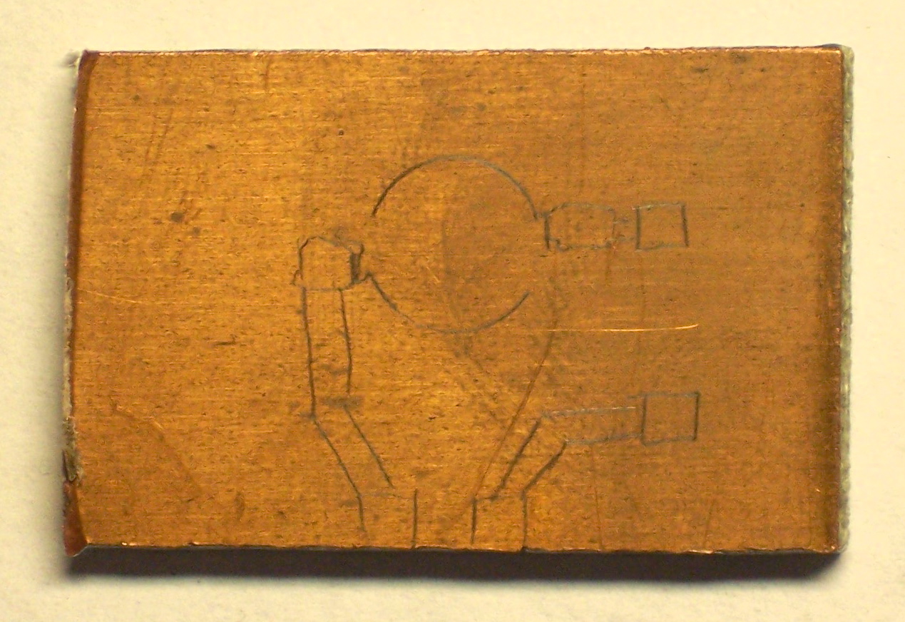
I outlined the paths I needed to cut to isolate the traces from each other,

then chucked a milling bit into a rotary tool and got to work.
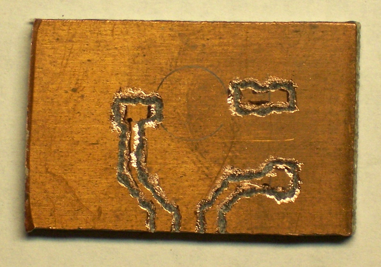
The milling bit has burred edges and was really intended for cutting PCB edges rather than milling trace isolation, so it did a pretty nasty job.
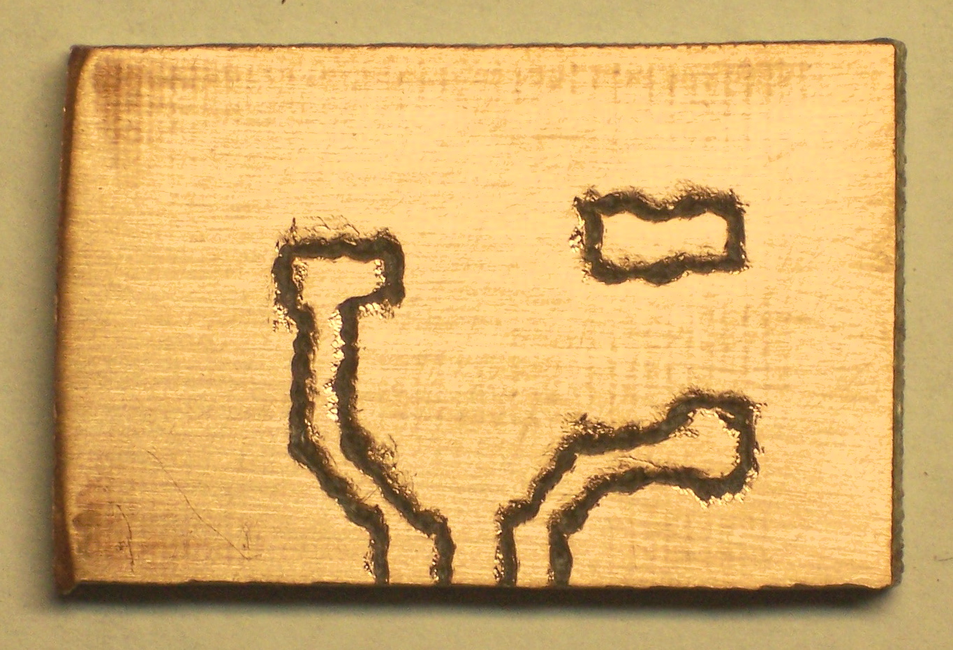
It cleaned up okay with some 600-grit sandpaper, though. I hadn’t bothered cleaning the board at all before I started, since I knew I’d want to sand to knock down the burrs after milling anyway.
Since I couldn’t find my old tube of thermal grease and my wife was running into town anyway, I asked her to pick some up for me. While I waited, I couldn’t resist soldering on the, uh, resistor.
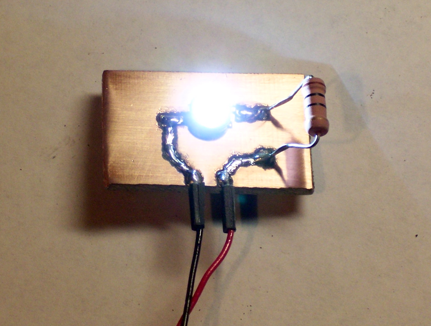
When she got back, I dabbed a little bit of thermal compound onto the LED’s slug, jammed it onto the board, and soldered it down. Its leads are pretty flexible, so I tack-soldered one, then pressed down on the LED’s lens to make good contact between the slug and the board while soldering the second lead.

I cut a couple of one-pin sockets, soldered them to the board, and was ready to roll.
Ow. It’s Bright.
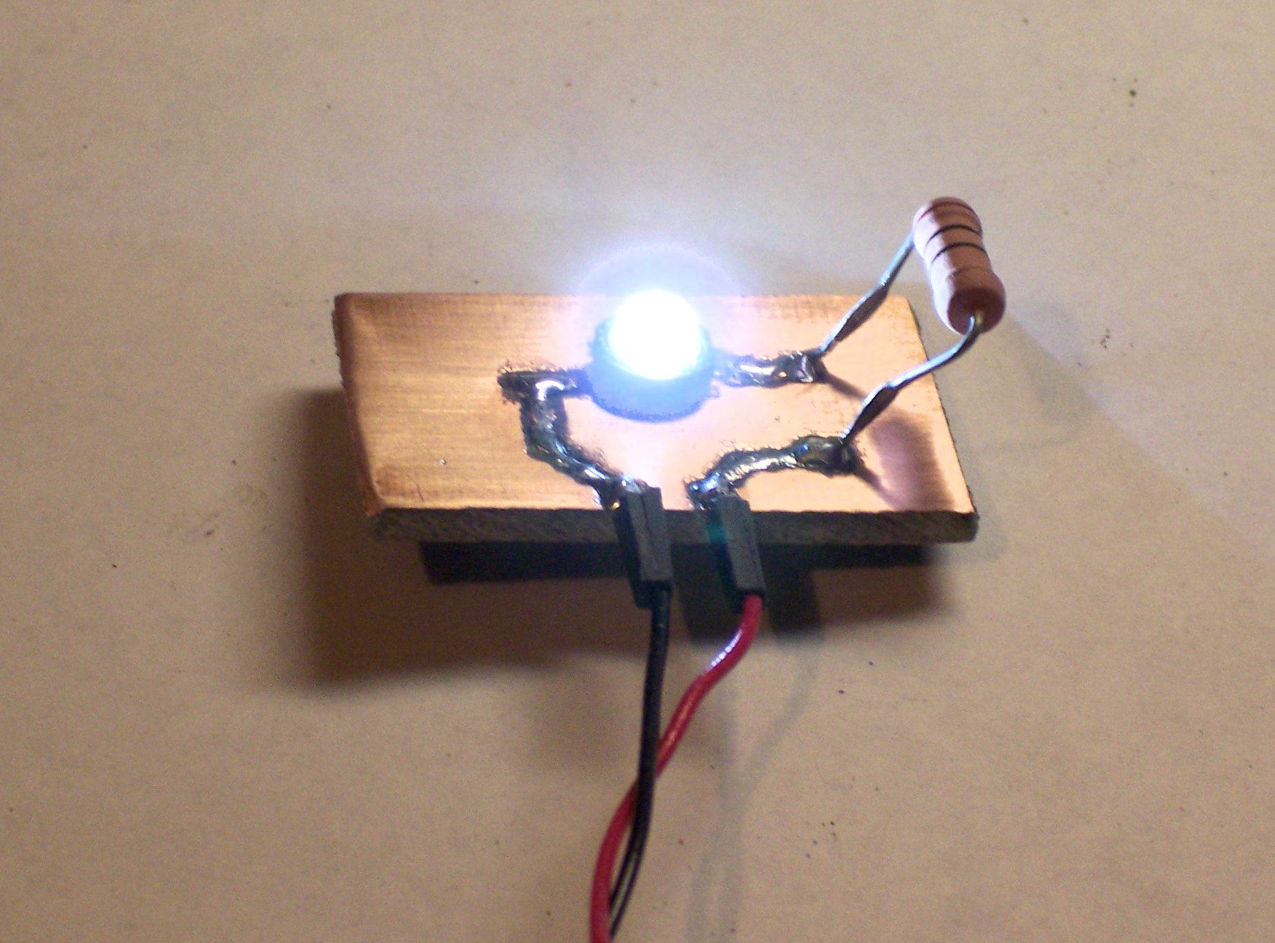
I wired the test board up to my bench power supply and eased up the voltage control. Around 3V the LED sprang to light: BAM, and it was on. From there to 5V, the brightness increased; and I can get even a little more by going up to 6V before I get nervous and back it off.
The LED is extremely bright, for an LED. I couldn’t get a good picture of it without my camera washing out–this is sitting on bright white typing paper directly under my desk lamp. Imagine the whole thing that much brighter.
Also, the Luxeon has a great viewing angle. They advertise it as 120°, and I can definitely believe that.
Turning out the room lights made for a good demonstration but another misrepresentative photo:
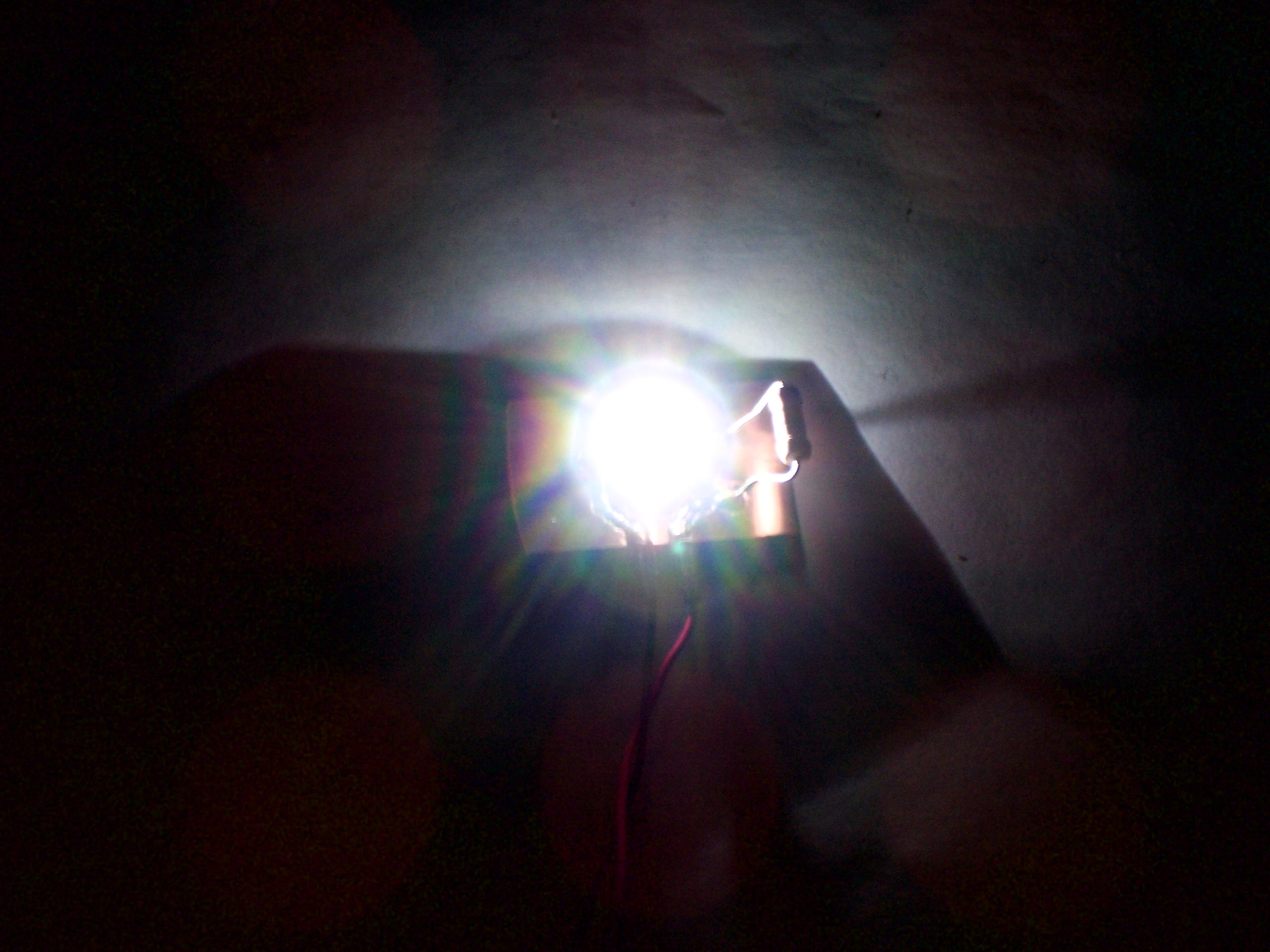
It lit the part of the room around my desk well enough to see, although not nearly as brightly as I’d like. I think the Luxeon I LEDs are rated at 40 Lumens, and a 100W incandescent is around 1600 Lumens. We have a ways to go before we’re lighting our houses with LEDs.
The batch I got was called cool white, and it had a very blue cast to it. I’m interested in getting my hands on some warm white next, and maybe some amber.
For now, I’m pleased with the results of the test. I can test different drive methods now, including replacing the 10Ω resistor with a smaller sense resistor if I choose. I have a visual reference of the apparent brightness, and I know I don’t like the color temperature of this particular bulb. And I measured the thermal temperature while it was running–the PCB right around the LED got up to 86°F after a few minutes while the rest of it stayed cool, which is good to know.
I just remembered I have a 1400mA Luxeon III that the eBay seller threw in with the Luxeon I’s I bought . . .