The stepper motors I’m using to build my CNC machine are rated for 2.5A. Now, when they’re holding one position, it’s easy to deliver 2.5A of current. But when the motors are rotating, their coils are being energized one at a time in sequence.
The coils are inductive, and inductors resist changes to current. So when a coil is first energized, it takes a moment for the current to build up to capacity. As a result, with a simple stepper driver, the faster you turn the motor, the less of the time each coil gets full current, and the weaker the motor gets.
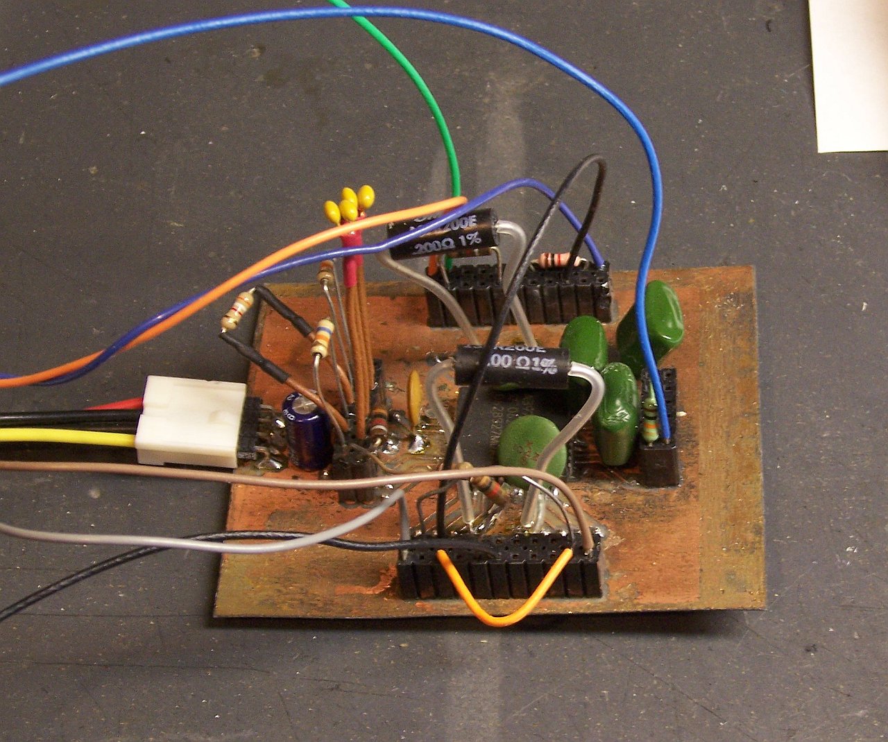
The Allegro Microsystems A3977 stepper driver chip I’m using to control my stepper motors overcomes this by running at a (much) higher supply voltage than needed to deliver 2.5A, and by using sense resistors in series with the motor coils. When it’s time to energize a coil, the A3977 delivers the full supply voltage and watches the sense resistor. When the desired amount of current is flowing through the resistor (hence the motor coil), the A3977 shuts off the voltage (briefly), then ramps it up again. The result is the delivery of the desired current on average, but with a much more rapid start due to the higher supply voltage.
Buried within Allegro’s A3977 FAQ is the recommendation that the sense resistors should be non-inductive. Since the values required are the sub-ohm range, commonly-available resistors are in big sand packages — and as noted by Jeff Mann in a comment posted about my control board, are internally wirewound and inductive.
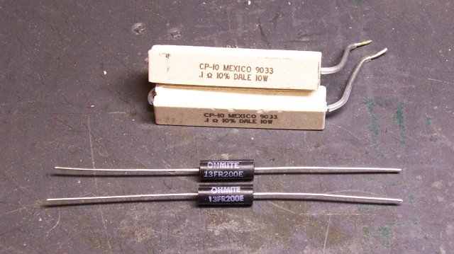
I had already bought Ohmite non-inductive sense resistors from DigiKey, which are also much smaller and more manageable than the big sand resistors. (The cross-section of the sand resistors is about 1/2″ square.) I hadn’t worked on the stepper driver in quite a while, though, and I hadn’t put in the noninductive resistors yet.
Did that Saturday. The difference in performance is amazing.
Performance Gains
The last time I did a speed test of my stepper motor controller, I was able to get about 500-600 steps per second before the motor started losing steps and stopped turning. Additionally, it growled and twitched when it was idle, and grunted and jerked at low speeds, smoothing out only at higher speeds.
With the non-inductive resistors installed, all the growling and twitching went away. (Someone should look at non-inductive resistors for bulldogs, but I digress.) I’m able to ramp the motor up smoothly from a stop to full speed.
And full speed has increased from about 600 steps per second to over 1450 steps per second, just from installing non-inductive sense resistors. With my 200 step/revolution motors and 20 tpi all-thread, that’s an improvement from about seven seconds per inch of linear travel to about three seconds per inch.
That’s still running on 12V out of my spare PC power supply, and I’m trying to rustle up a 24V supply to test with, which should increase the speed further. That’s also without tweaking the A3977′s component values — I hear there are some tricks to play there, too.
Executive summary:
Inductive sense resistors with the A3977 make the motor growl and jerk when idle and at low speeds, and limit maximum speed. Non-inductive sense resistors with the A3977 make the motor smooth and quiet at all operational speeds, and dramatically increase maximum speed.
Z Axis Completely Assembled
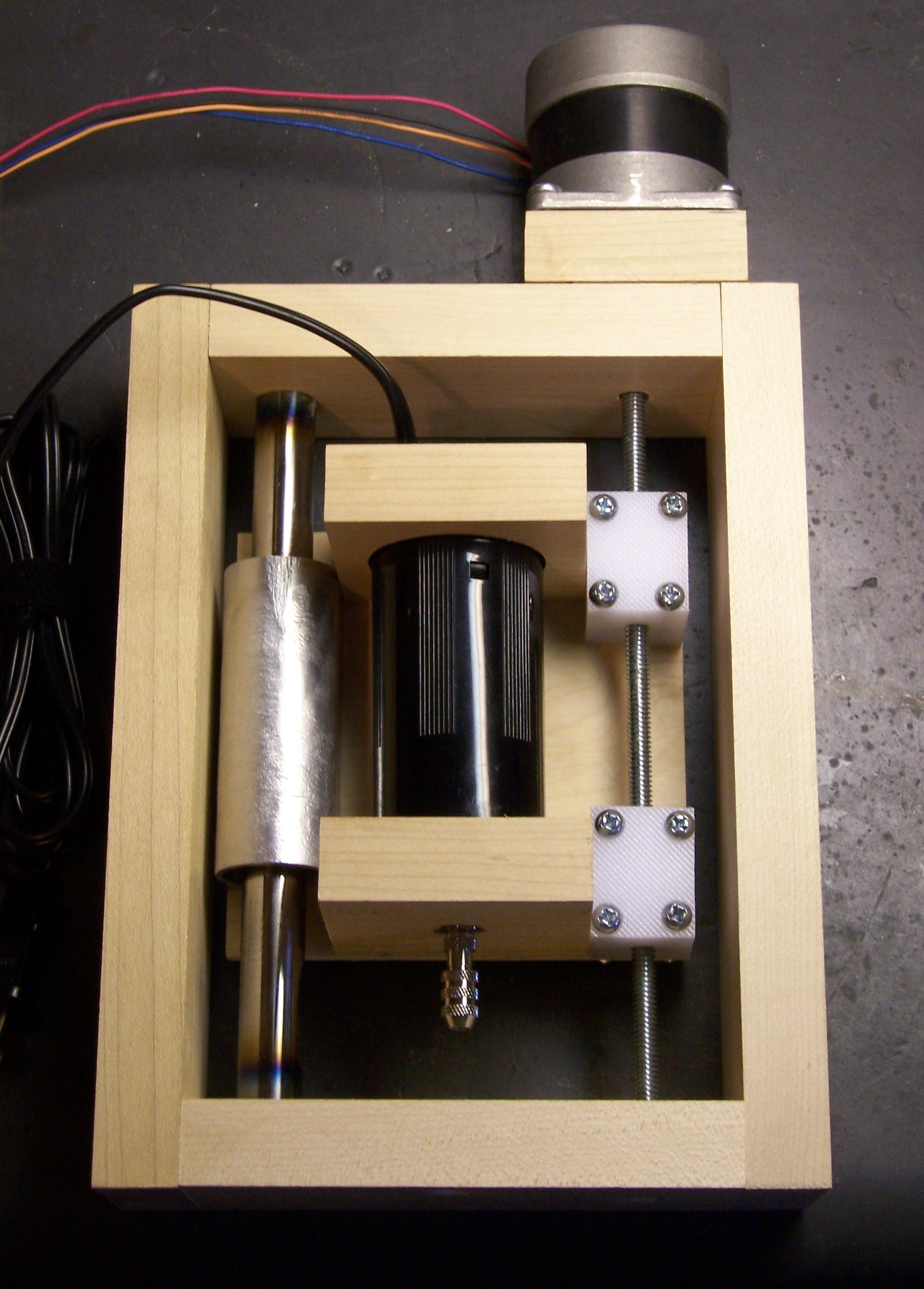
I have the drill sled mounted in the frame, the motor properly mounted, and the joystick controlling it at variable speed. Next step is building the Y axis around the Z frame.
Credit Where Due
Many thanks to Jeff Mann for his original comment, which drew my attention back to replacing the sense resistors, and for our followup conversation, which helped me understand and think through how the PWM driver makes the motors work better at higher voltage without going over the rated current.
Keith,
It looks to me that you have very thin screw so any resistance from the tool (when it hits the hard surface) will break the alignmen and can lock the screw. This kind of a design doesn’t save you from some backlash (even if you have this thick printer rod as a stabilizer) – this makes the carriage very sensitive to the rsistance from a work surface when the tool touches it. Be carefull here.
Hi, Igor!
The scale of the picture may be deceptive — the screw is 1/4″ thick. Two friends of mine have home-built CNC drill/mill machines with the same screw, so I know from experience that it’ll be adequate for my use. And anecdotally, I can’t resist the movement of the platform by hand.
Another consideration is that since this is inexpensive hardware-store all-thread, the threads have a V profile. For a larger machine and/or for cutting harder materials, I’d definitely use a leadscrew with Acme or square threads.
If I misunderstood your point, I love to hear more!