According to the explanation in my previous post, the Allegro A3977 stepper motor driver should be able to run motors faster with a higher load supply voltage. Naturally, I was eager to see this for myself.
Yes, yes it does.
Throwing Together an Unregulated 18V Power Supply
I’d been using my benchtop PC power supply for both 5V logic and 12V load supplies. After swapping the sense resistors this weekend and improving my step rate from 600 steps per second to about 1450, I was really curious how much of an additional improvement I’d get from a higher load supply. The 3977 is rated for a 35V load supply, but some forum posters recommend going no higher than 30V, so I was looking to try out 18-24V.
Joel just dismantled a photocopier with 20V motors; but after looking at the power supply boards, it wasn’t obvious which of the several power supplies was the one providing 20V. Plus they were switching supplies, and I don’t know whether they had integral loads or whether I’d have to provide a minimum load externally . . . bluck.
So I hacked together my own ~18V supply.
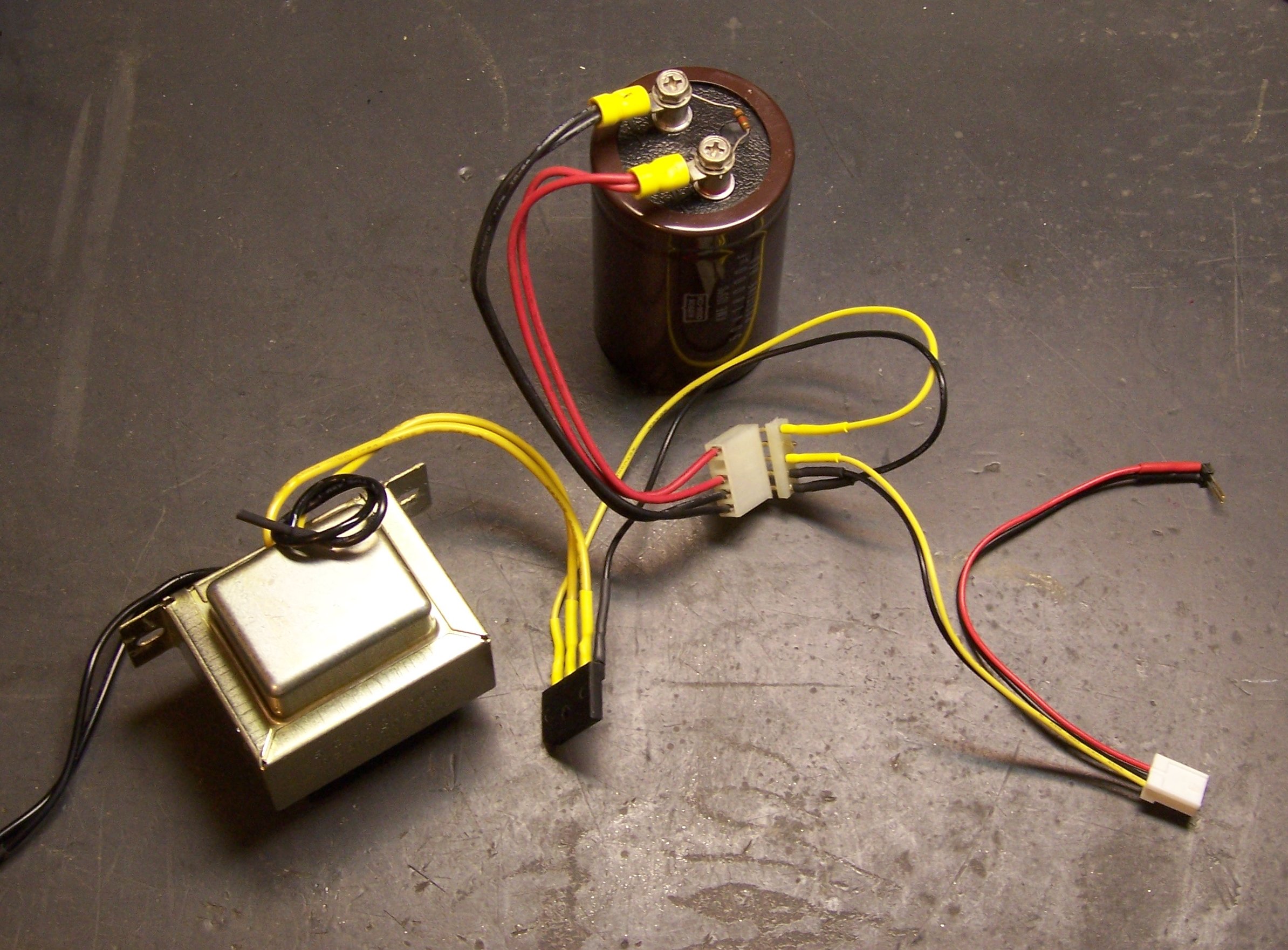
From left to middle to top, that’s a brand new Radio Shack 12.6V 3A transformer, 4A bridge rectifier from a dead PC power supply, and a 18000μF capacitor out of a workhorse Accel printer from a former employer. The line cord is from a broken coffee grinder, the five-pin socket came with the capacitor and the plug from Slim, and the remaining wires and connector are from the PC power supply.
Side note: I’ve seen a few big capacitors in my day, but these impress me. When servicing these printers, I once vaporized a chunk out of my pocketknife’s screwdriver blade when I discharged the big capacitor by accident. I know personally that the last time this capacitor’s printer was powered on was no more recent than 1998. On a lark, after getting the capacitor out of the printer, I put a voltmeter across it, and it still had 3V on it. Ran an LED for a couple of minutes while I was draining it. I screwed a 1KΩ resistor across it to drain it a little faster in my power supply, so I don’t have to worry as much about hurting myself.
Power Supply Calculations
I have never kept the formulas for different rectifiers in my head, so I’ll run through the numbers for this one here. The transformer’s secondary (V2) is 12.6VAC RMS, and the peak voltage of a sine wave is RMS * √2, so the secondary peak voltage (VP2) is
VP2 = V2 * √2 = 12.6V * √2 ≈ 17.8VDC
The peak DC output of a bridge rectifier (VP) is the peak secondary voltage minus the two diode drops, so
VP = VP2 – 1.4V = 17.8V – 1.4V = 16.4V
The output of a capacitor input filter is the same as the peak DC value of its input, minus load-dependent ripple, so I should be getting about 16.4VDC out of this setup. Measured about 17.1, so I’m in range. The transformer is rated for 12.6VAC output at 3A, so it’s almost certainly putting out a little higher voltage with such a light load. If I weren’t so lazy, I’d go measure it, but that’s out of the question. ![]()
And there’s no regulator. Linear regulators convert electricity into heat, and I need neither less electricity nor more heat. The A3977 is effectively a switchmode regulator for the motor coils anyway; so by regulating its input load supply voltage too carefully, I’d just be duplicating effort. Especially for a test. Note that I’m still running the logic supply voltage from the well-regulated 5.0V output of my PC power supply — the red and black wires in the photo above are picking that up and adding it into the four-pin supply jack.
With my scope across the capacitor terminals, I estimated .2V peak-to-peak ripple when running one motor at full speed. That’s pretty lousy ripple for most digital or analog circuits, but by all appearances just fine for this application. Especially, as I intend to keep pointing out, for a test. ![]()
And Yes, the Motor Runs Faster
The motor is running noticeably faster before losing steps — up from 1450 steps per second to about 2300 steps per second. That’s an improvement from 2.8 seconds per inch of linear travel to 1.7 seconds per inch — a considerable difference for something as simple as changing the load supply voltage.
I want more, of course. I still want to see what happens at 24V and at 30V, so I bought a bargain 24V power supply on eBay today. When it gets here, I’ll give it a shot.
It’s worth noting that as far as I can tell, I don’t need to change anything in the A3977 circuit to adapt to the new load supply voltage. The sense resistors determine the maximum current that should flow through the motors, and the whole job of the 3977 is to keep that the same regardless of supply voltage. And I provide VREF from a divider on the logic supply voltage, so that’s also independent of load supply. Slick.