2020 extruded aluminum (so named for its 20-mm-square cross-section and not, confusingly, for the year that I bought it) and its larger siblings seem to be the preferred current construction set for engineers. Each face of the aluminum sticks has a T-slot that accepts a nut or the head of a custom machine screw, allowing the sticks to be fastened together without drilling holes and thereby facilitating rapid physical prototyping.
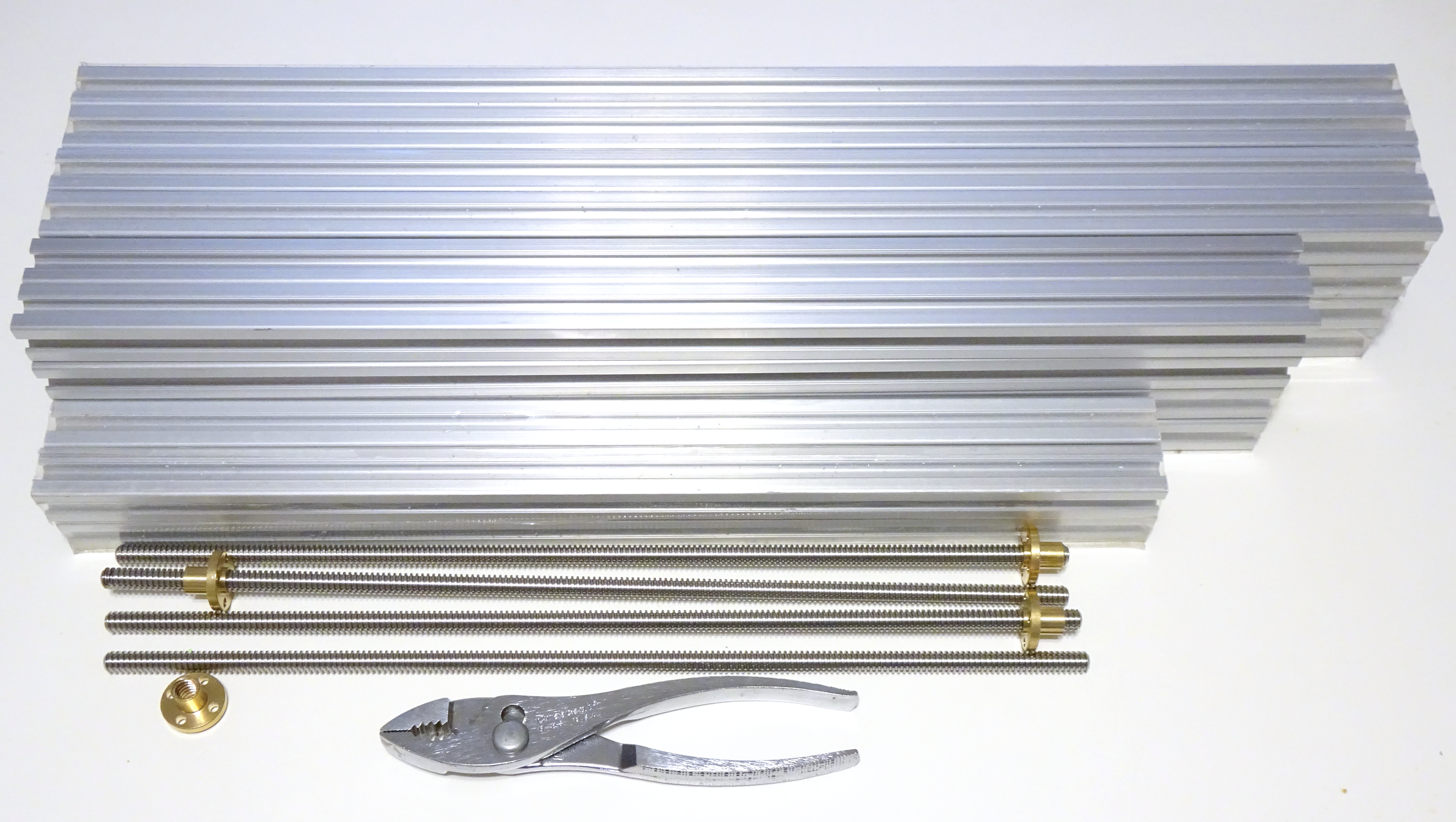
I recently ordered a stack of 2020 extrusions pre-cut to several lengths I wanted to play with. It was my first foray into AliExpress, which (that particular foray) went quite well. The tidy pile above cost me only a little over $100, the best deal I could find in several places I looked.
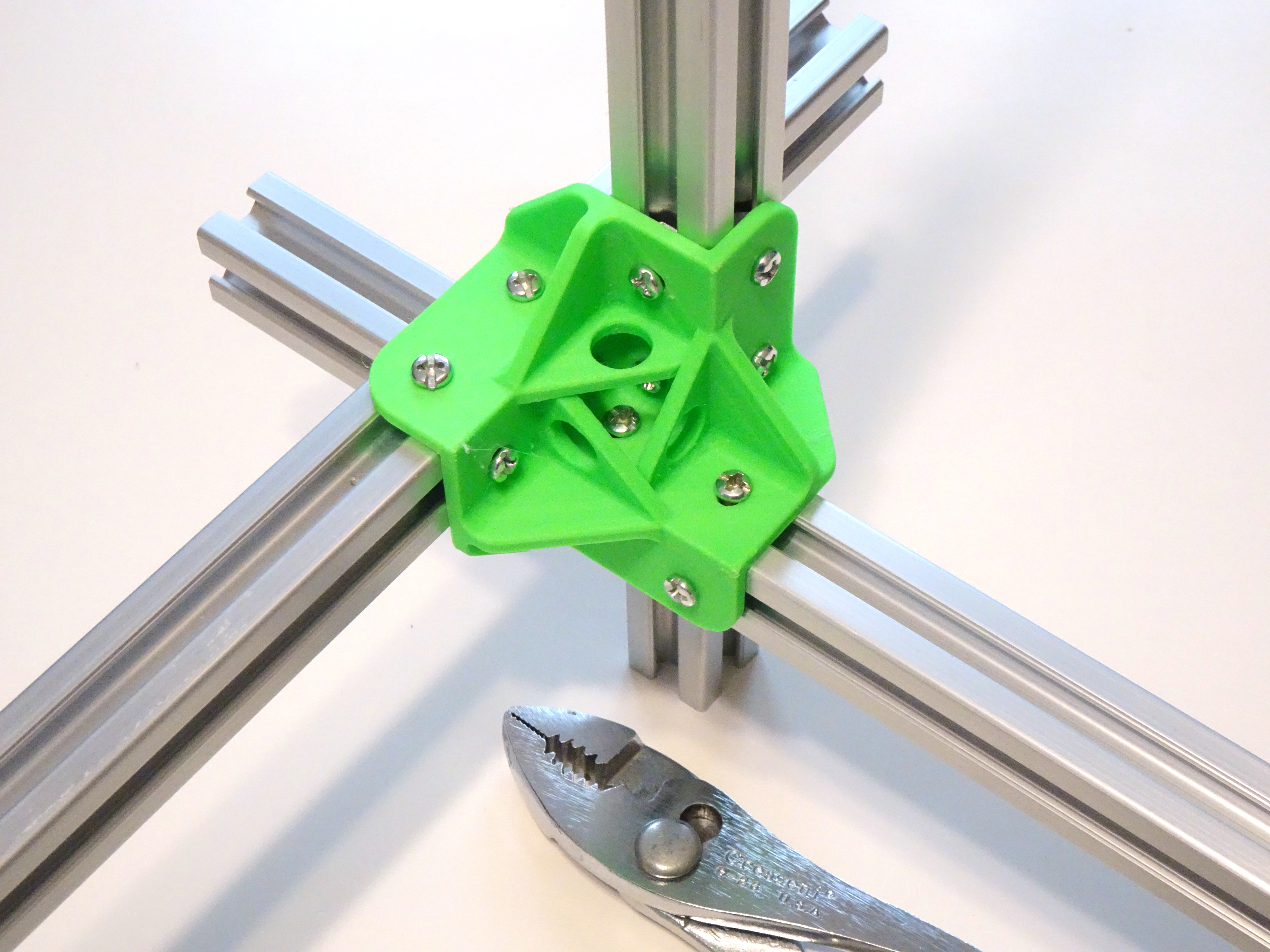
Since receiving that shipment, I’ve been prototyping brackets for attaching 2020 extrusions together. Shown here is the overly elaborate last one I’ve tried, because I didn’t get good pictures of the earlier attempts in action.
Brackets for attaching 2020 aluminum extrusions are readily available, so why on earth would I be trying to print my own?
Well, the commercial brackets tend to be designed for butt joints, with the end of one stick pressed up against a face of another stick. Using butt joints requires cutting pieces to length which requires knowing what length you want them; whereas I don’t know exactly what I might want to build and would like the flexibility of attaching longer pieces together without cutting, and maybe even loosening the fasteners and sliding the sticks around to get the exact size I want.
I envisioned doing that using lap joints, with the face of one stick pressed against the face of another stick. Making a three-way lap joint with three sticks at right angles to each other in three dimensions reminds me of the wooden burr puzzles that are popular in my mom’s extended family; so I’ve been thinking of these as burr brackets (though I’m not notching the aluminum as the wood is notched in a burr puzzle).
Variant 1: Friction Ain’t Enough
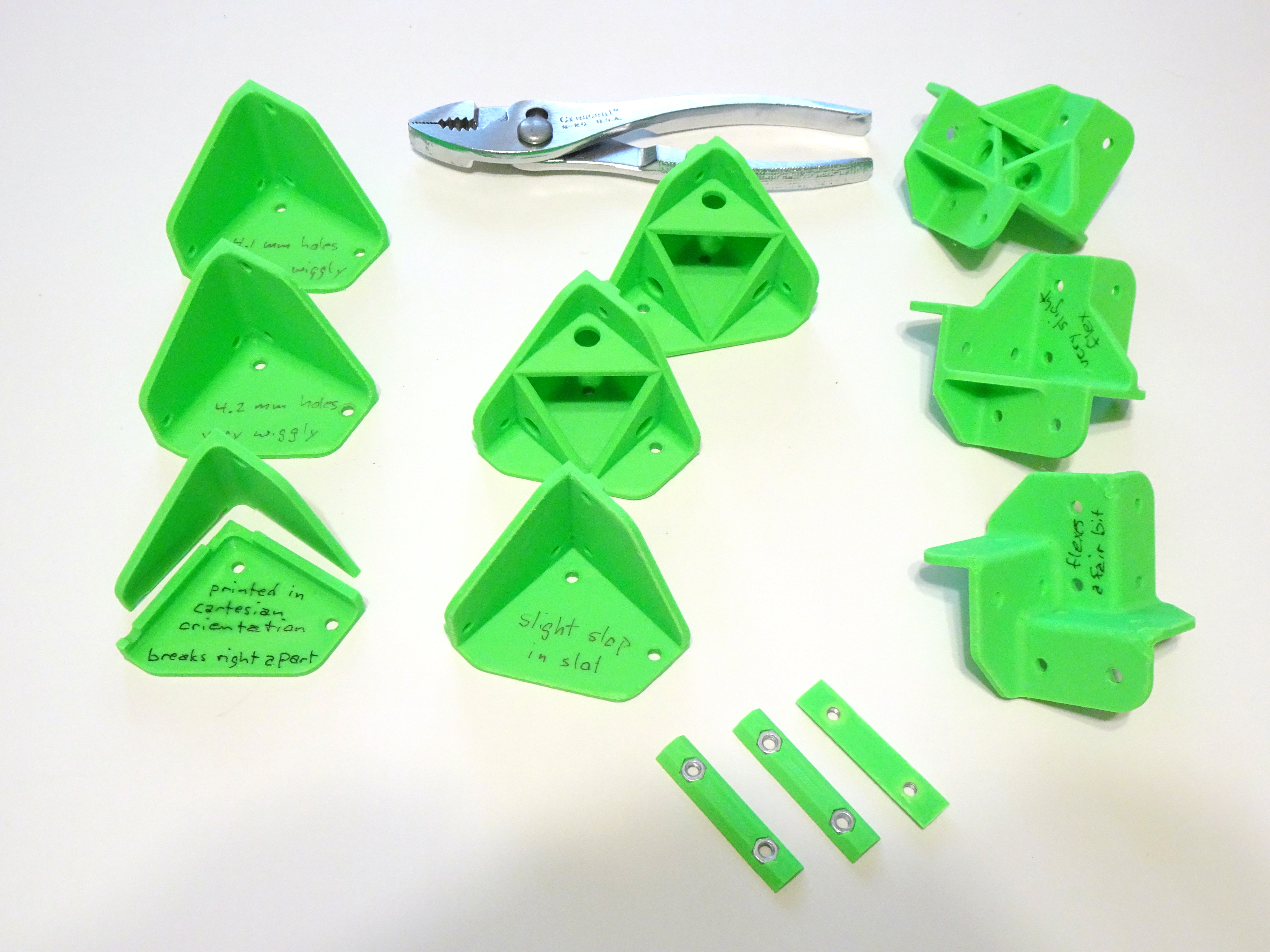
I’ve iterated through several repetitions each of three design variations. The brackets in the first batch on the left simply bolt onto T-nuts in the T-slots. Applying relatively little force to see how much I could flex the bolted-together extrusions, the first bracket shattered along the printed layer lines. All subsequent brackets were printed in an orientation of looking down into or up out of the corner (rotate the part around the X axis by M * 90° + 45°, then around the Y axis by N * 90° + atan(1/sqrt 2) ~= 35.264°) so that the holes aren’t close together on the same layers.
After printing a stronger bracket in the new orientation, the printed holes (nominally 4.2 mm but no telling what size they actually come off the printer) still had enough slop on the M4 machine screws for the aluminum sticks to slide and deflect about 1 cm at their other ends — way too much if you’re building a frame that’s supposed to be perpendicular. Reducing the holes to nominal 4.1 mm reduced the play of the M4 screws in the holes but resulted in the screws “leaning” as I applied torque to the joint, for still about 5 mm deflection at the ends of the sticks.
Variant 2: Keyed Tabs Ain’t Enough
My next design variation put keyed tabs onto the brackets, to try to lock the bracket’s angle with respect to the slot and counter the torque when flexing an assembled joint. The metal T-nuts I have stick far enough out of the slot from below to interfere with the keyed tabs; so I also printed custom T-bars with shallower tops than the metal T-nuts (pictured further above).
This combination provided enough additional resistance against rotation that the flexing of the 3-mm plastic walls became the primary contributor to movement of the sticks. I added bracing, which made the bracket rigid enough that the issue moved back to the fit of the keyed tab and T-bar in the slot. Around this time, I noticed that the T-bars fit differently into difference slots of the same stick; so relying on the dimensions of the keyed tabs and bars against the dimensions of the slots is a losing game.
Variant 3: Grab Two Sides
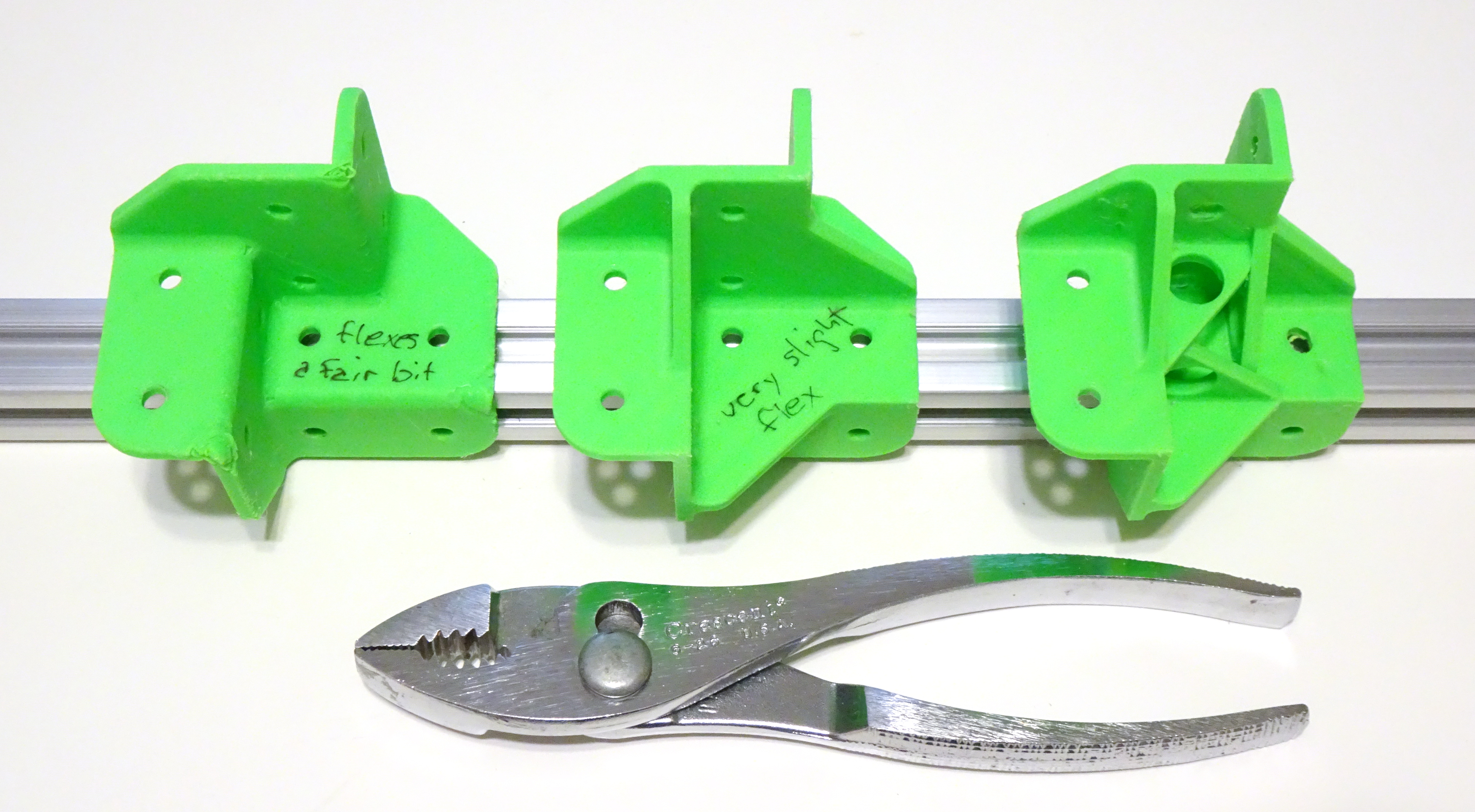
The final variation acknowledges that all of the above methods are ultimately trying to use the clamping force of a small machine screw to generate enough friction between two smooth surfaces to keep them from shearing, which, nope. Not at this scale.
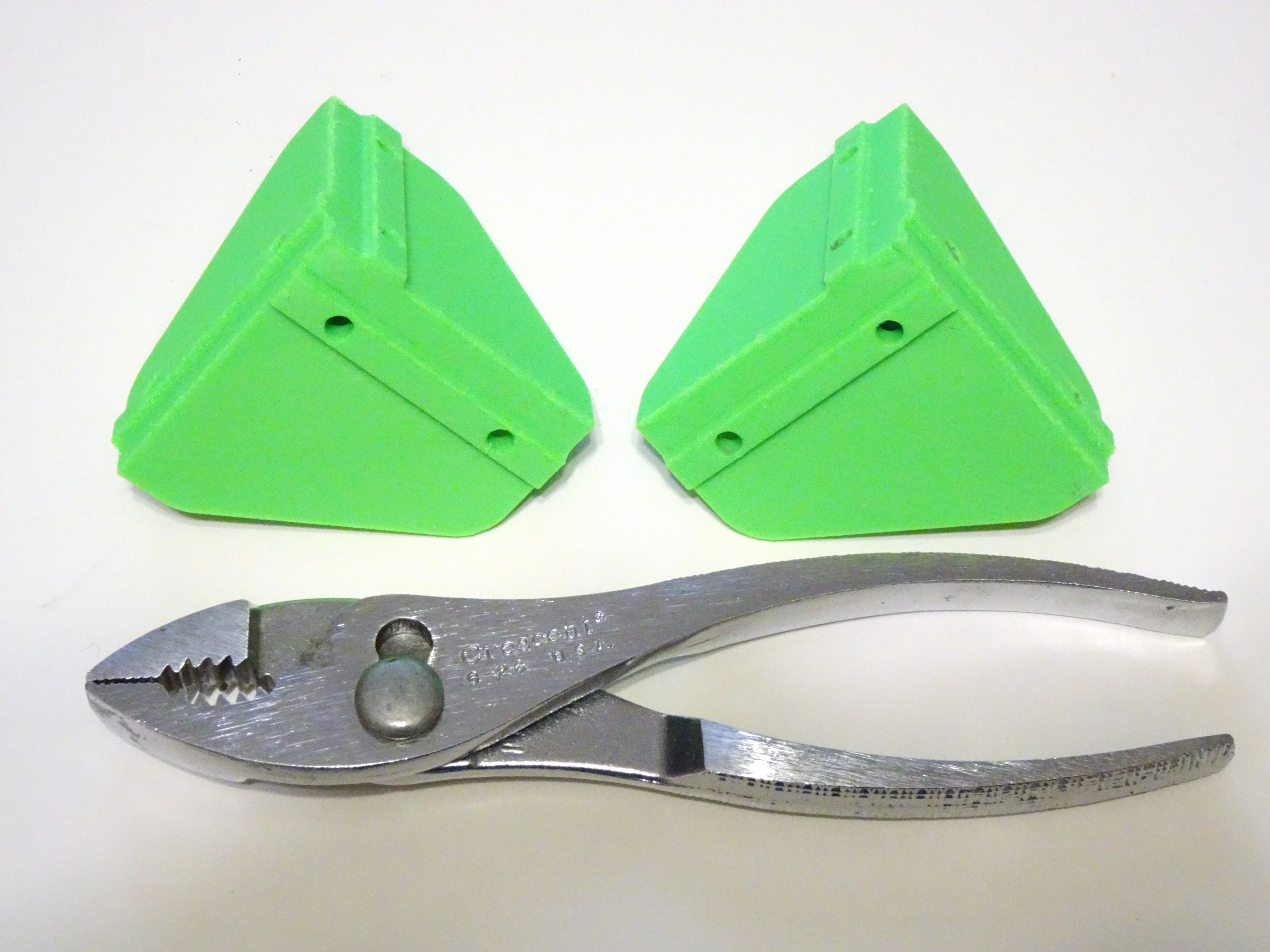
Instead, just grip the aluminum extrusion on adjacent faces and let the clamping force prevent movement in the direction it’s good at. Indeed, this design variant does not perceptibly slide against the aluminum at all, and the sole detectable remaining issue was flexing of the plastic. I printed three of these alien hothouse flowers with increasingly contrived bracing; the second is probably Good Enough and the last is probably Really Good Enough.
Of course, I can increase the wall thickness to increase the bracket rigidity if I later decide they’re still flexing too much; but first, I want to see how they do in ABS, which I expect to be less rigid (bad) but also less brittle (good) than this PLA.
All of these, btw, were designed in FreeCAD, which has a workflow like CATIA (and presumably like other contemporary modeling software that I haven’t used) and is da bomb if you want to use free-as-in-beer-and-speech software for 3D modeling and you thought OpenSCAD was all there was. I am lovin’ it and it makes it really easy to do things that are really hard in OpenSCAD, like, y’know, fillets.
T8 Lead Screws
If you’re building some kind of contraption out of 2020 extrusions, chances are fair you’ll want parts of it to be moved by motors. Two common ways to accomplish that are timing belts (not shown) and pulleys (the awesome OpenSCAD parametric pulleys by droftarts) and lead screws, which I also ordered on AliExpress.

Lead screws have three important dimensions — the diameter, the thread pitch, and the lead pitch.
The thread pitch refers to the center-to-center distance between adjacent threads, measured along the length of the screw (parallel to the axis).
The lead pitch refers to the center-to-center axial distance between appearances of the same thread — because leadscrews can have multiple threads on them, also referred to as “starts”. A single-start lead screw is like a candy cane with a single red stripe. A two-start lead screw is like a candy cane with a red stripe and a pink stripe, each separated by a white stripe. A four-start lead screw is like a tutti-frutti candy cane.
With a 2-mm pitch, a single-start lead screw has a 2-mm lead; a two-start lead screw has a 4-mm lead; and a four-start lead screw has an 8-mm lead.
I ordered a four-pack of T8 (8mm diameter) 2-mm pitch 2-mm lead lead screws and matching nuts and received … four T8 2-mm pitch 2-mm lead screws, three T8 2-mm pitch 2-mm lead nuts, and one T8 2-mm pitch 4-mm lead nut.
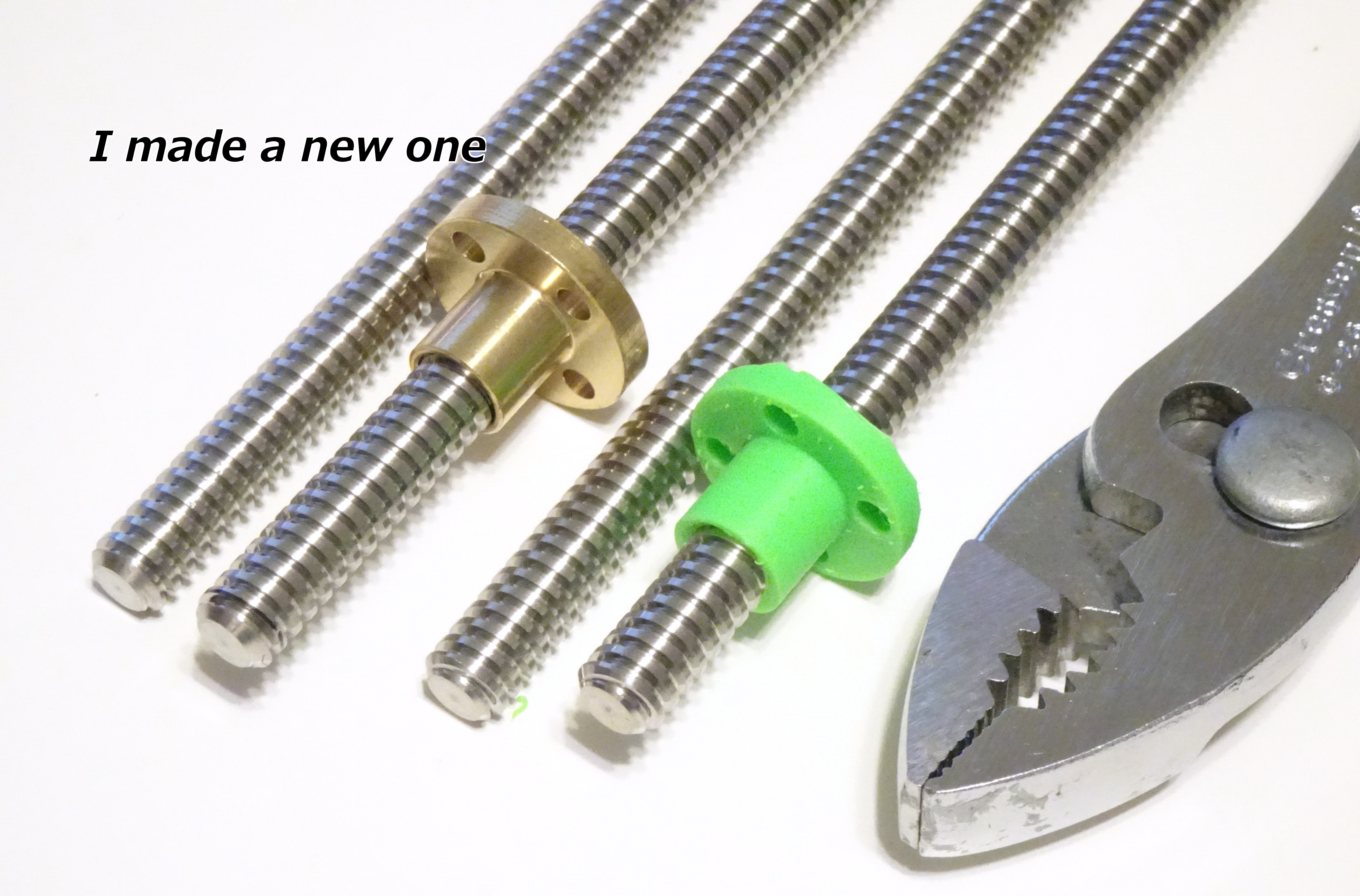
Just for fun, I designed and printed a replacement T8 2-mm pitch 2-mm lead trapezoidal nut in the same style package as the bronze nuts that I ordered. I had thought of this style of lead screw as Acme; but in looking up the dimensions to draw in FreeCAD, this fine document taught me that the angle between adjacent thread walls is 29° in Acme threads and 30° in the trapezoidal threads used in metric lead screws — hence the origin of the fancy name “trapezoidal nuts.” I stand educated.
are these freecad files for the brackets available? I have the exact same issue, doing some prototyping where I need to move some stuff around and make sure it fits before ordering custom fits. Let me know.
Thanks for your time.