The Voron community comes across as antagonistic about a number of issues, one of which is: If your build surface is perfectly flat, there’s no need for bed mesh leveling!
Well, if your build surface is perfectly flat, good for you.
Even then, it would be more accurate to say that if your Voron 2.4 build surface is perfectly flat, the Voron is intrinsically incapable of using bed mesh leveling to improve it. (The Voron 2.4 levels the gantry to be parallel to the build surface by probing near the four corners. If the plane of the build surface isn’t square to the vertical members of the frame, the Voron has no way of determining that it’s always going to print non-rectangular parallelograms in the X-Z and/or Y-Z planes. But I digress.)
My aluminum heat spreader is not perfectly flat because it came in a kit from Fysetc rather than from a milling machine with a fly cutter; and my Voron 2.4 benefits tremendously from bed mesh leveling. (Above, without; below, with.)
To take my mesh to the next level, it’ll help to get the bed mesh configuration correct. The provided configuration is a useful starting point but can be improved significantly.
Introduction
Bed mesh leveling is a means of dealing with irregularities in a 3D printer’s build surface. Think of it as terrain-following radar for an experimental aircraft that we might send Clint Eastwood to steal. If we try to print the first layer planar when the build surface is varying, the first layer will be deposited at different heights and different amounts of squish above the build surface, causing different amounts of stick. Mesh leveling adapts the first layer to be nonplanar and follow the curvature of the build surface, then “fades” back to planar printing over the first several layers of the print.
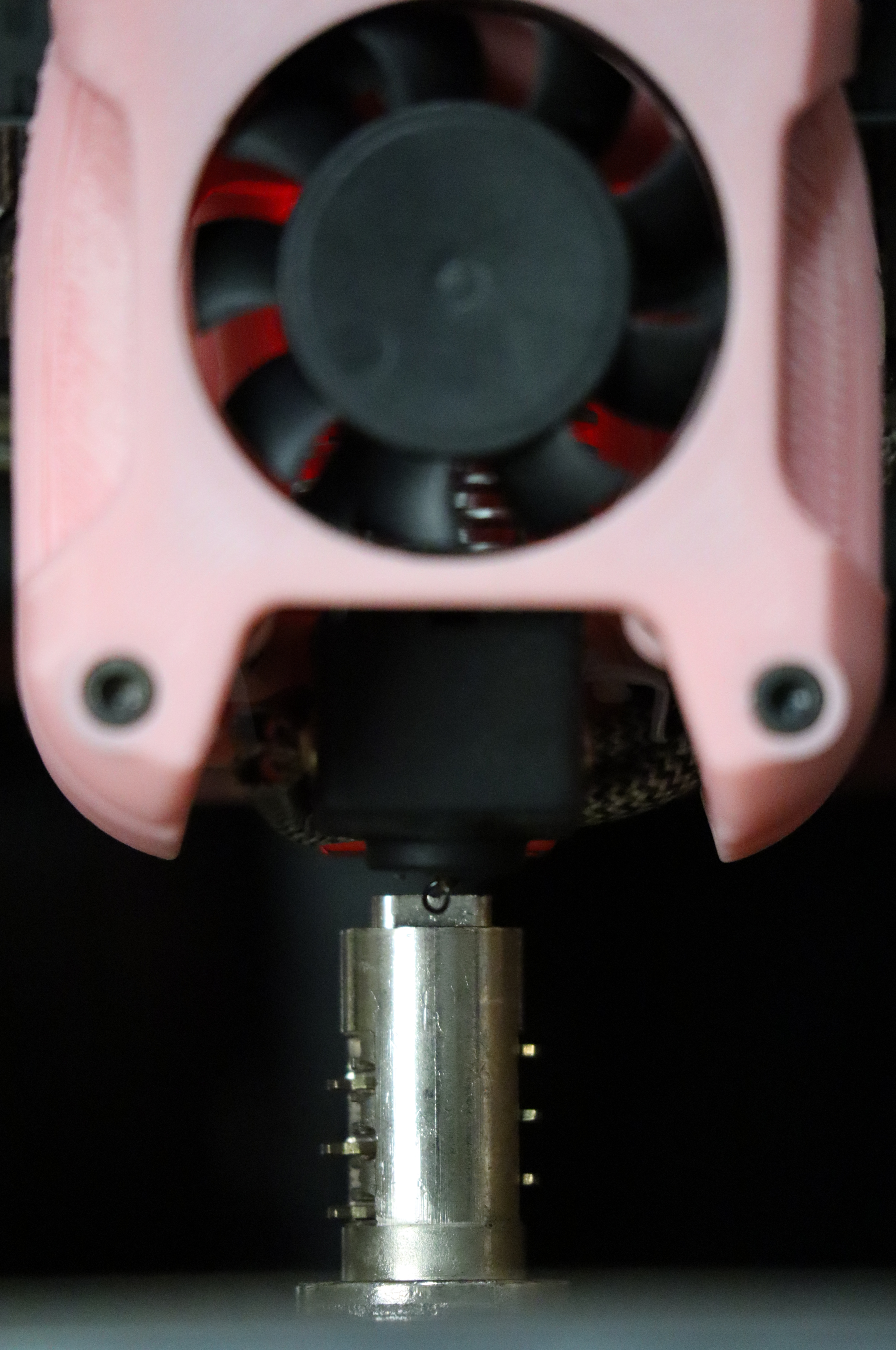
To learn what terrain it needs to follow, mesh leveling probes the surface one time, or once before each print, typically using a probe attached to the toolhead. Inductive probes measure the distance to the metal underneath the build surface (so they don’t know the actual distance to the top of the surface); contact probes measure the distance to the top of the surface (so they don’t know the depth of any texture). The Fysetc parts kit for the Voron 2.4 includes an inductive probe.
Probe X-Y Offset
bed_mesh_clear

g28

quad_gantry_level

g28
The first thing I wanted to confirm was the offset from the nozzle to the most-sensitive spot of the probe so that I can later set the mesh probing perimeters accordingly. To do this, I:
- cleared the existing mesh (important to do before any calibration operation to ensure that the firmware isn’t modifying your Z coordinates according to a mesh)
- homed the printer to set the Z offset
- did a quad gantry level to set the gantry planar to the build surface
- homed again (important to do after the gantry leveling so the Z offset is relative to the trammed gantry)
Then I:
- sent the printhead to the center of the build area (
g0 x175 y175) - used OctoPrint’s Control menu to jog the printhead high enough to center a piece of metal underneath the nozzle (the nozzle being the point from which X-Y coordinates are measured)
- jogged the printhead to position the probe over the piece of metal and jogged the printhead around until I found the X-Y coordinates at which the probe triggered highest (at the furthest distance, meaning at the X-Y offset with greatest sensitivity)
- issued
m114to query the current coordinates and found that to be 22 mm behind the nozzle (close to the 25 mm in the sample config) - entered that into my
printer.cfgfile
[probe]

...

y_offset: 22.0
Probe-able Perimeter
The provided configuration probed 40 mm away from the perimeter of the build area, which gave some very odd results that are important in my next post.
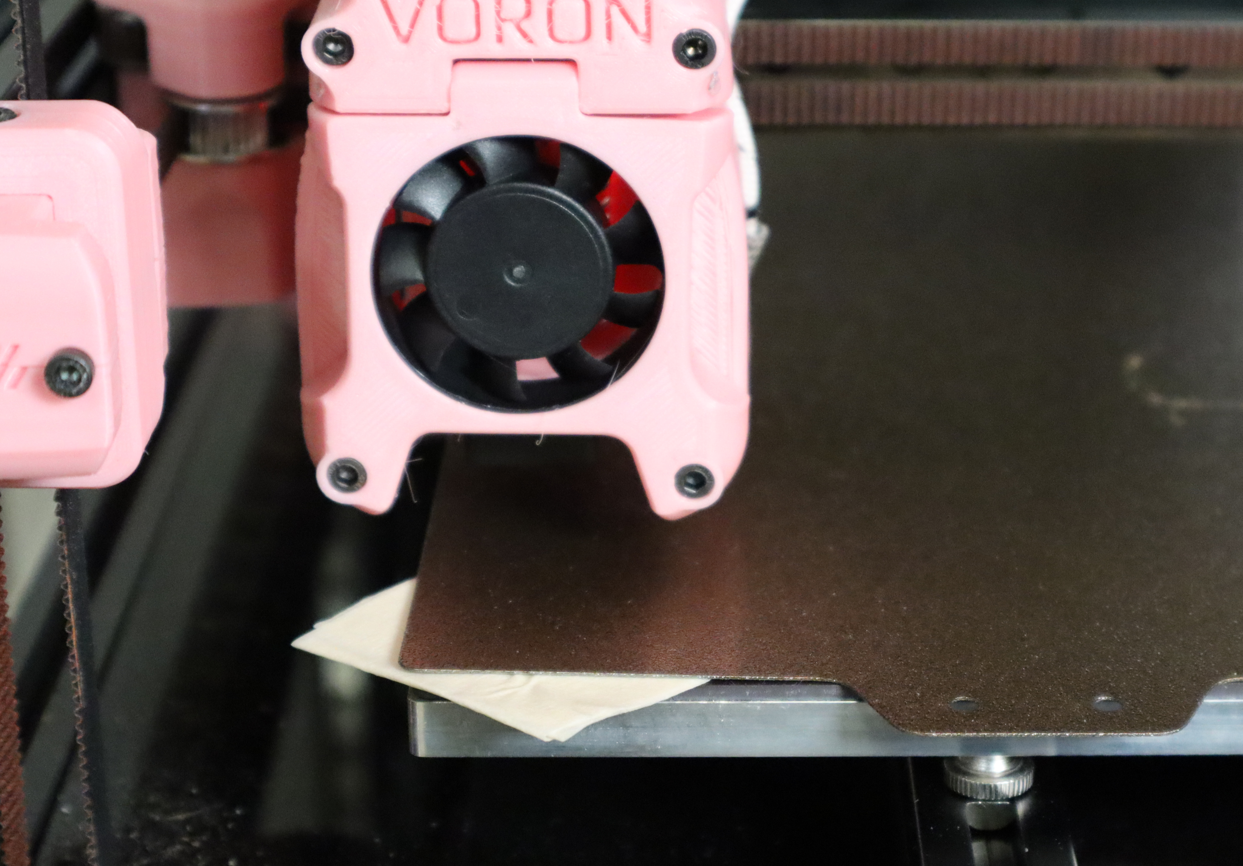
I used OctoPrint’s Control to jog the toolhead to each edge of the build surface, testing the height at which the probe triggered, to determine how close to each edge it’s able to measure the height reliably. I found a dropoff in sensitivity about 4 mm from the side edges, so I decided to probe within 10 mm of the sides for a margin of safety.
At the front of the build platform, the relative positions of the nozzle and probe mean that the probe can’t get closer than 22 mm to the front edge, which is fine. At the back of the build platform, sensitivity dropped off around toolhead position Ynozzle=319, which means Yprobe=341, or 9 mm forward from the back edge; so probe as far back as toolhead position Ynozzle=315 for a margin of safety.
[bed_mesh]

...

#       probe with nozzle at Y=0, probe at Y=22

mesh_min: 10, 22

#       probe with nozzle at Y=315, probe at Y=337

mesh_max: 340,337
Paste in the sample configuration from the Voron page and then update with our new information. I found the Klipper bed mesh configuration instructions confusing, but here’s the scoop: The min and max probing positions are specified as the probe coordinates and the probing process takes into account the offset specified earlier.
I updated the configuration and added comments that disambiguate the coordinates. This configuration to probe closer to the edges of the build surface relieved the worst of the oddities that I’ll describe later.
OctoPrint Bed Mesh Visualizer Inverted Y Axis
I had one more peculiarity in my bed mesh results to understand, so I shimmed up a corner of the spring steel build surface with a stack of masking tape (heaters off — for real mesh testing, you want everything hot so it takes into account the same thermal expansion that occurs during warmup for a print; but for this test, I don’t want baked masking tape); reran the homing, gantry level, and homing; and ran a bed_mesh_calibrate with 11×11 probing for testing.
The bed mesh visualizer is an OctoPrint plugin — go to Wrench / OctoPrint / Plugin Manager / + Get More and enter Bed Visualizer to install it. Then go to the Bed Visualizer tab, Update Mesh Now, and drag the view around to examine your probed build surface mesh.

Yeah, my shimmed spot is in the front left corner and it’s being reported in the back left corner. That’s not right.
Bed Visualizer has controls to flip and to rotate the view and I didn’t know yet whether my results were flipped in Y or rotated CW. I repeated the test with the shim in the front right corner and the high spot moved to the back right; so I knew that Bed Visualizer was flipping my Y axis.

After going to Bed Visualizer / gear / Collection, checking Flip Y-Axis, saving, and re-updating the mesh, I now have a correct visualization of the terrain of my build surface. Which (the build surface) is awful. Ignoring my shim, it has 0.4 mm variance between the high and low spots. We’ll have to do something about that.