A few weeks ago, a reader who goes by Mikey asked:
I’d like a device that connects inline to the speaker output(s) on my home stereo amplifier between the amp and the speakers that has led indicators that flash with the audio signal that passes through the speaker wire.
We have outdoor speakers on our “B” channel of the amp. On many occasions, we forget to turn them off, and I’d love some type of indicator that would be on/flashing when the speakers are in use. This would remind us to turn them off.
Any ideas how to build a device like this, or somewhere to go?
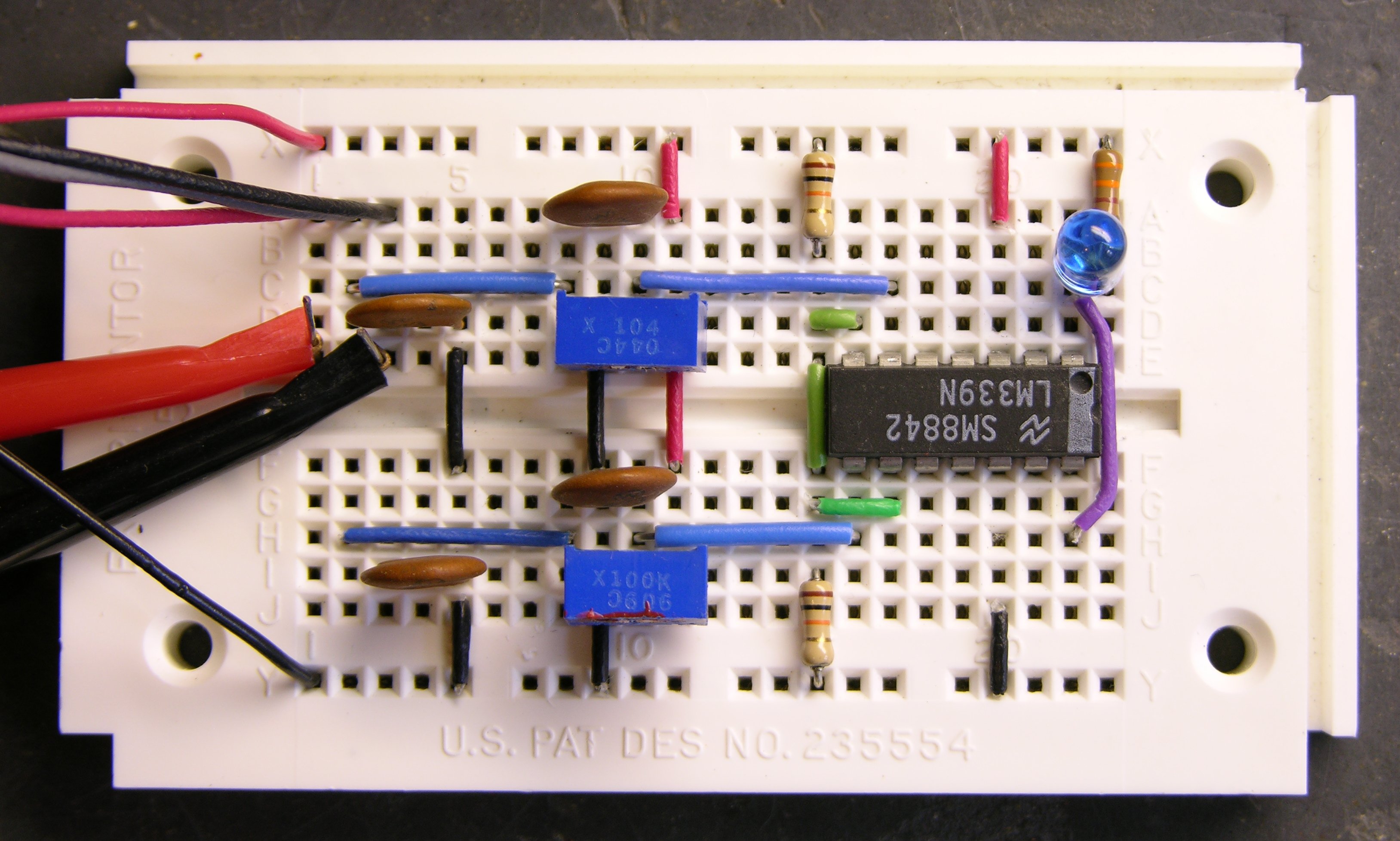
It seemed like an interesting request, potentially useful to other folks, and easy enough to build. I’ve had a little time to play this week and hacked together a prototype, which I’ve posted here along with schematic, parts list, and build instructions.
Love your projects. They’re an inspiration to budding hobbyists like myself. Keep them coming!
I don’t like the speaker input connections. As you mentioned, you’re just asking for trouble with that capacitor to ground. I’d, at least, put a series resistor in the ground lead to limit the lower value of the impedance.
Also, as you note, you really need to protect the LM339 from excessive voltage (both positive and negative peaks?). While the potentiometers should work most of the time, there’s always the chance that someone will tweak them when they shouldn’t (party guest?), or that someone will hook the circuit up with them adjusted the wrong way. In cases like this, I like to use a series resistor to the input of the device to provide some impedance, and then a pair of Schottky diodes, one connected to the power rail and one connected to the ground rail. This limits the maximum voltage swing on the input of the IC to a maximum of about .2 Volts above the power rail, or -.2 Volts (below the ground rail). If the voltage tries to exceed this, the Schottky diodes start conducting, dropping the excess voltage across the series resistor. But, in normal operation, the voltage doesn’t exceed the limits, and the Schottky’s never conduct, and the series resistor doesn’t adversely affect the voltage to the input of the chip.
Oh, this may be especially important if the user happens to be using a speaker line output rather than an 8 ohm speaker. Speaker lines usually run about 70 Volts (or so). The advantage to this is that they run at a considerably higher impedance, which minimizes losses in long runs (e.g., think PA systems and those speakers).
Something else to think about, although it’s probably not a big issue, is that speakers also function as microphones. Thus, there may be a chance that, even with the amplifier switched off, if the potentiometers are adjusted to make the device extremely sensitive, that noise or (especially) wind blowing against the speaker may develop enough voltage to flash the LED.
The wire-or connection on the output is a neat trick.
Dave
Another idea is to have a relay that cuts the speakers off after a certain period of no audio. That would solve the forgetting problem as well, making it more automated.
Richard, are you thinking you’d then have to press a button to latch the relay again, the next time you want to use it? I guess that could work.
Of course, it doesn’t solve the problem of having a patio party that migrates indoors without ever slowing down, and late at night you realize you’ve been blasting your neighbors the whole time.
nice idea!!! maybe you can help me because i always thought about a way to automatically turn my aplifier off via a relay conneted to a electronic that detects the “no-signal” afer a specific time.
but i am not good at those things….i don´t have enough tecnical know how to build such a circuit.
Chromo, I’ve done exactly what you want as a separate project — my amplifier power sequencer. I haven’t written up the circuit yet, though — I’m making a couple of changes and working on packaging (a nice case).
Once it’s done, I intend to publish complete instructions, and offer PCBs and complete kits to build it. Would you (or anyone else) be interested in one? Rackmount or box enclosure? Assembled product or kit to build yourself? I’m not asking for a commitment — just trying to gauge interest.
Keith,
Excellent idea. I have a similar situation and have been pondering how to resolve it the best way. I was going to go the route of a countdown timer. You can get them as lightswitch replacements for your outdoor lights. Just tap the button and the light stays on for 1,2,4,8 hours then automagically turns off. Build a circuit around that or use the light switch to power a small amp (I think they are only good for about 500w with the built in relay).
Cool idea on your amp sequencer. I am a fan of the SAE line and have the 102 series preamp and tuner. One thing that I have come across in my beginnings with the PICAXE was this great little circuit for getting the most out of your inputs if you need multiple push button type controls. I hope this helps you in the future. Great site. I have RSS’d it into my Bloglines.
Link here to circuit here: http://www.lancer3.com/ADC%20Keypad.htm
Kris (and others) –
The amp power sequencer is intended to control all your amps by watching your inputs (DVD, tuner, etc.) and/or preamp to know when it’s time to turn on. It can signal “smart” amps to turn on and off, or you could use it to power relays for “dumb” amps.
I’m leery of providing instructions for hooking up relays to switch 110V for liability reasons (doesn’t it stink that fear of random lawsuits from individuals who don’t want to accept responsibility for their own actions keeps me from sharing useful information with the world), but you could easily add them yourself.
The speaker power detector is more of a hack with a little different target, when you already have a multichannel amp setup and you want a reminder when one set is on.
With your SAE preamp, you already have the best of both worlds. But your timer idea for the speaker control is kind of neat — you sidestep the problem of knowing whether the outside speakers are on by making them turn off automatically. I like that, too.
great idea with the amp power sequencer.. a kit would be nice…
especially for a “dumb” amp with adjustable timer..
i would to have such a kit
You could dump the input-stage capacitor, and actually work with either speaker polarity, if you put a small audio transformer in:
On the input side, put your transformer coil in series with your 20-100K pot, hooked up with the wiper tied down to one end of the pot. This should give you a variable resistance that always stays big enough to protect both the amp and the transformer. Obviously, the output side of the transformer goes into TRIM1.
Hey, I just realized you can get rid of C3 and C4 as well this way, since the transformers will block the DC for you!
I’d really like to see something like this developed for a car audio application.
Car audio amplifiers put out alot of power, and when they peak, they can damage a speaker by driving it too hard. I’d love to see a project that could display actual wattage somehow (digital or LED) and let me know when my speakers are trying too hard and when I should back off the gain adjustment. If you’re really ambitious, something inexpensive that could also detect amplifier clipping and warn the user could make millions.
polarity, i thought that the audio signals were alternating current, i don’t see how you can hook it up wrong, then again, i haven’t looked at the schematic, but still, it puzzles me.
Andres, yes, audio signals are AC. But in most consumer-grade receivers, only one of the two speaker leads has the AC signal; the other is neutral and connected to ground.
Miswiring L(signal) to R(signal), or worse, L(signal) to R(ground), would short the output and would probably be fatal to the output transistors.
Make sense?
Hi Keith,
Great site!
Have you come out with the “revision” to your speaker detector yet? This is exactly what I need, an inline speaker detector for my surround sound! I want to put inline LED indicators on each of the five channels!
Thanks, sjh
Steve, sorry, I haven’t done the revision yet. (I see I thought I’d have that done by November.)
How soon would you be wanting to build it?
Hi Keith,
I would like to build one as soon as possible, but think I need to wait for the “revision” because my surround sound speaker connections are not tied directly together, ~18K resistance between R- and L-.
What are your thoughts regarding the input redesign, maybe a transformer or optocoupler?
Best Regards, Steve Haran
Im trying to do something similar here except the audio input will be coming from the signal that goes to a cellphone speaker. The relay will be need to be able to replace a push switch on a wireless remote powered by a 1.5v battery. Is that even possible to use a audio signal to power a relay, (maybe charge up a capacitor and then let that power the relay). I only know basics about electronics. Any help would be appreciated.
Tim, I don’t think you’ll be able to power a relay with the audio signal, and I also suspect that this particular circuit is more than you need for what you want to do.
Tell me more about your project and the functionality you’re after and I’ll see if I can suggest something.
How many time have you wanted to start your car using your remote start and it didn’t reach? You still had to either go up to the window or actually walk outside to get close to the car? Well, The idea that had was to put a remote inside the car and get a prepaid phone. Connect the speaker output a circuit that will short the switch just like pressing it. Set all my calls to blank ringer, or no ringer except the one from my phone so when I call it will send a ringer to the circuit to activate the relay. There are services that can do this but they cost about 140 bucks a year. With a prepaid phone it would be free because you you would technically never answerer the phone. In theory it sounds like it would work. Thanks.
Tim, you already have the remote start, right? (I can’t tell you how to wire an ignition switch if you don’t already have that done.) And it’s smart enough not to try to start the car if it’s already running?
Power this circuit from your cigarette lighter, or some other fused 12V source in the car, and I think everything else will pretty well follow from there — I think most of this circuit will work exactly as it is. And you don’t need to worry about the caution I posted to people with stereos — that only applies when you’re connecting two inputs, and you’ll only be using one.
Let me know how it goes! And of course be careful; I can’t take any responsibility for what you build when I’m not there to watch. But the fact that you’re connecting a cell phone (low voltage) to a wireless remote (low voltage) and only connecting to the car’s 12V system to get power for this circuit makes it a lot safer to do.
This circuit is simple , but very good
I ever built it and work very weel..
Thanks
Hi Keith,
After much searching (and confusion) I’ve come across your 2007 Speaker Power Detector design. I’ve been looking to add pulsating led pilot lights to a pair of old AR-4x speakers that I’ve just done some crossover work on. Your circuit looks like it may work for my purposes if it can be modified to work with only one speaker input. Can I just eliminate the bottom part of the circuit going to the second speaker?
I’m a photographer that has some electronics background (a long time ago) Thanks for your help and cool blog!
Phil
Phil, yes, it would work great with only one speaker input — in fact, splitting it in half would eliminate all the cautions I was issuing that stemmed from using it with two speakers.
Just remember that you’ll need to provide a DC power source to run the IC.
You might prefer to substitute a dual comparator like the LM393 — I only used the LM339 because that’s what I had on hand.
Good to hear that! I’ll give it a try and let you know how it works out.
Thanks Keith,
Phil
Hi, Keith — after much Googling to solve my problem of inadvertently bothering the hell out of my neighbors with my outdoor speakers, I found your blog! The last time I built a circuit was in college introductory physics (pretty sure that was just a battery and a lightbulb) — so needless to say, this is the first real circuit I’ve ever built. But the good news is, I’ve done it and it works…kinda. The problem I’m having is that I can’t get the LED to stay solidly lit at my desired low volumes. It flickers, but I want it to be ON. I’ve adjusted my trimpot to be JUST under the reference voltage and I have my speaker pot turned all the way up — still no dice.
I used my voltometer to measure the voltage across my speaker terminals, and at the volumes I’m interested in, it fluctuates between 15-25mV. That seems shockingly low. Turning it up to the top of the range at which I’d normally listen, I got 200-200mV; and at the absolute max volume my receiver is capable of, I got 1-3V. My A/V receiver is a Yamaha HTR-5860 (110W per channel) — is it odd that the voltage is that low? (And if the voltage is that low, is there any reason for a speaker pot at all?)
So, big question: Any thoughts on how to get that LED to stay solidly lit at these low voltages? My goal is to have that LED on solid if ANY voltage is in the line of my outdoor speakers.