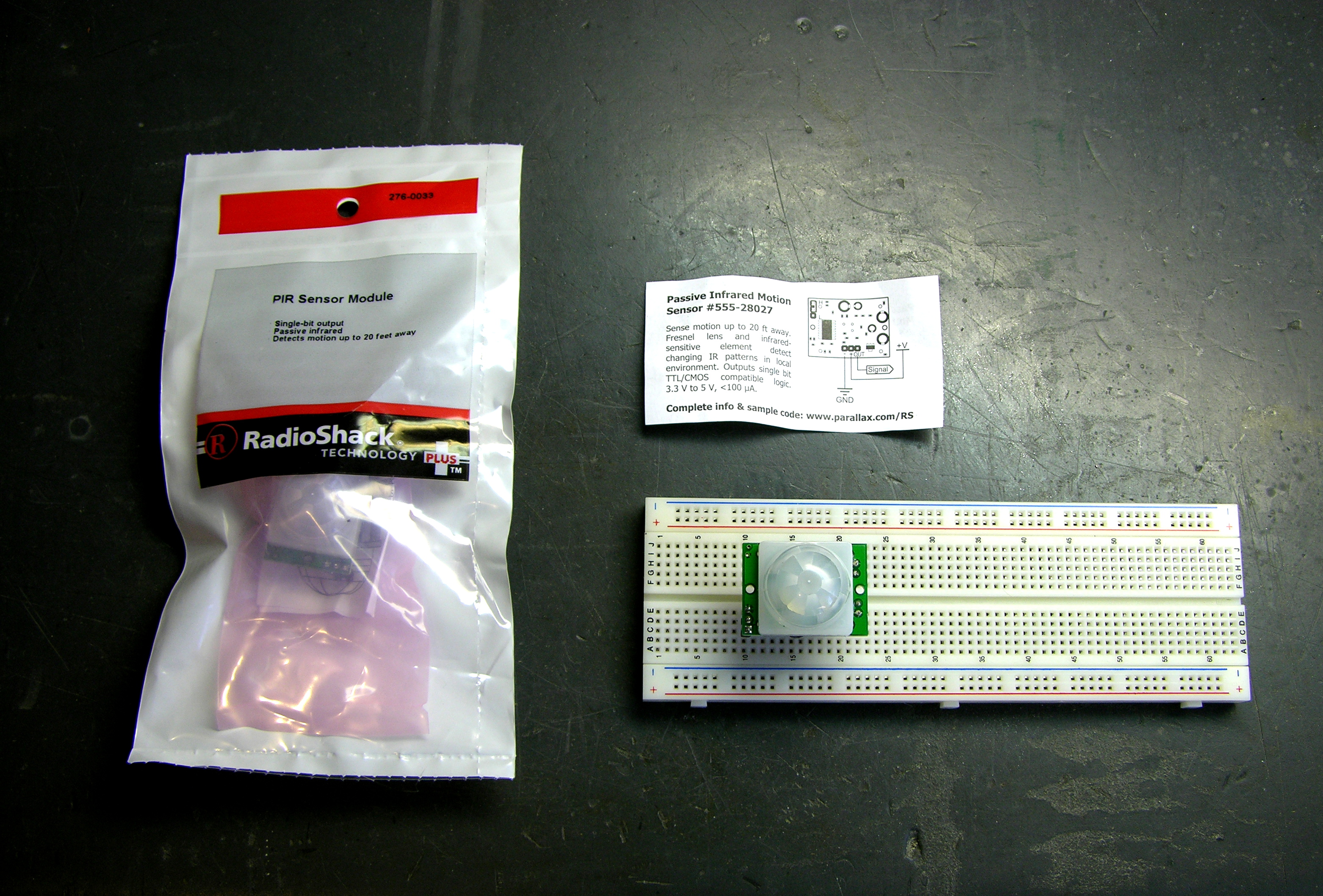
The back cover of Servo Magazine is always an ad from Parallax, and the December issue featured several sensors that will now be distributed through Radio Shack, including a motion sensor for $10.
John and I are getting ready for this spring’s Technology: Art and Sound by Design class; and although I think John will be doing most of the teaching this year, I’m always on the lookout for sensors that would be good for students’ interactive sculptures.
Jason at work suggested that the LED puck could have a motion-sensing mode, to serve as a sort of intrusion alarm.
When two separate events occur simultaneously pertaining to the same object of inquiry, we must always pay strict attention. Or, ah, three events.
I picked up a couple of the sensors last week to try out. The clerk said when they got them, he had thought they’d never sell any. Why am I always the guy buying the weird stuff?
How Motion Sensors Work
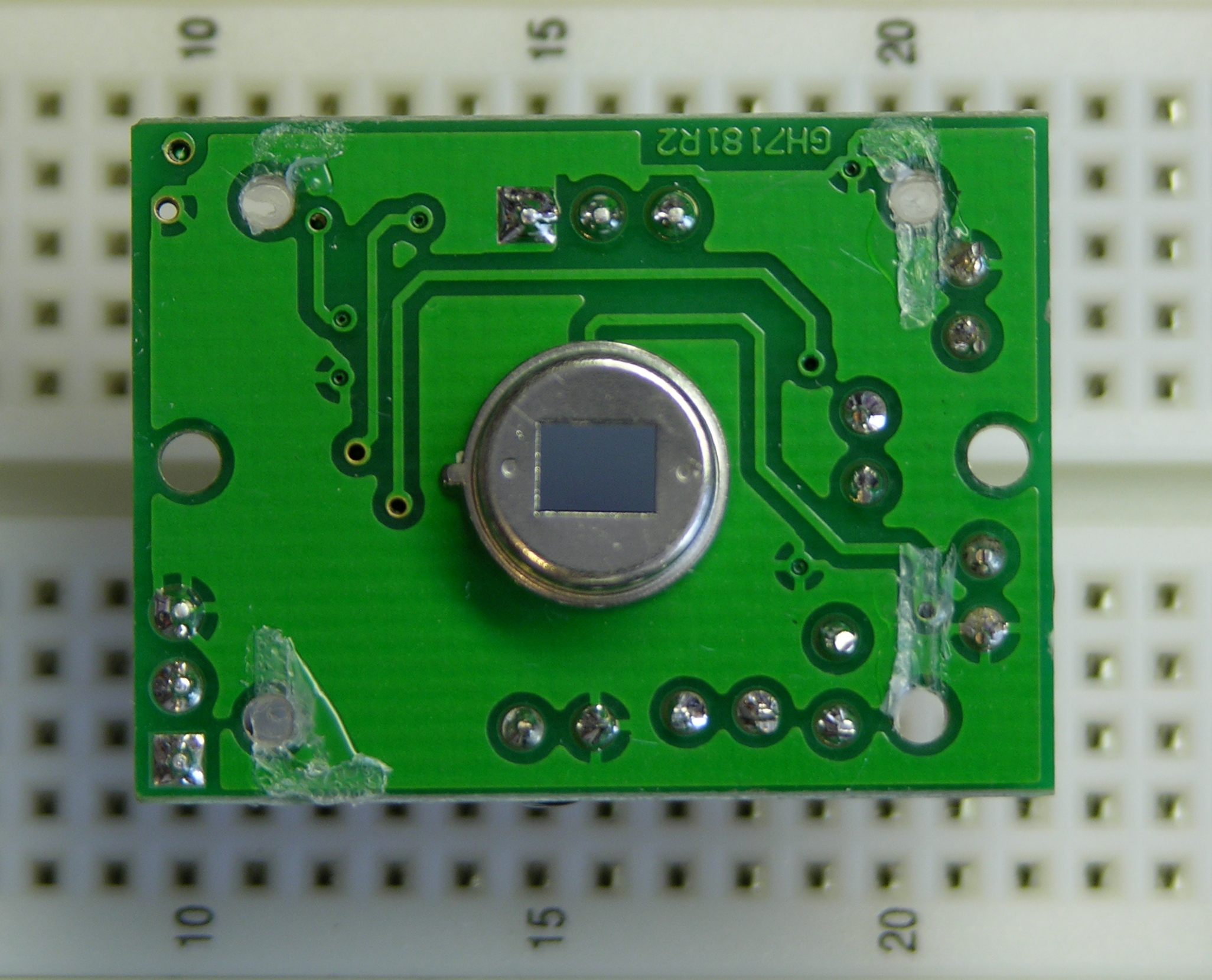
The heart of common motion detectors is a pyroelectric sensor, which is essentially a FET with a window in the case opening onto an infrared-sensitive gate. Changes in the level of IR light with a wavelength corresponding to body heat cause changes in the drain-source resistance, which the circuit monitors.
The real trick is that the sensor is then placed behind a multifaceted lens that (loosely speaking) “chops up” the view of the world into smaller cones of heightened visibility and intervening areas of lessened visibility. Think of a stage polka-dotted with multiple spotlights, only actually seeing that way rather than merely illuminating that way.
A body moving from an area of reduced visibility into an area of increased visibility causes a rapid change in the amount of IR (body heat) shining on the sensor, hence a rapid change in its drain-source resistance. The motion detector circuit watches for these rapid changes, and when detected, triggers the alarm. This is why Robert Redford has to move slowly while retrieving the MacGuffin from Cosmo’s office in Sneakers.
A brief note about the multifaceted lens: It is usually a Fresnel lens, but being a Fresnel lens is a red herring. That simply makes the lens thin and easy to mold out of plastic; it is really the multifaceted nature of the lens that’s important. Closer examination of a motion sensor lens easily reveals that it comprises multiple adjacent Fresnel lenses.
The Fresnel dome of this sensor, by the way, is too large to fit into the LED puck (as, most likely, is the PCB). However, it’s not out of the question to purchase a separate PIR element and mill a multifaceted lens pattern into the puck enclosure above it. It would be an interesting challenge, perhaps for a later version.
The Parallax Sensor
The sensor comes with an absolutely minimal connection diagram, and refers to the Parallax web site for full documentation. The module has a three-pin connector (bottom) for ground/V+/output, and a two-position jumper (upper left) for retriggering mode.
The power/output header is annoyingly the same height as the other components on the back side of the board, so the sensor cannot be plugged directly into a breadboard for prototyping; it requires an extension. Parallax recommends a servo extension cable; I soldered a three-pin header to a three-pin header socket to make a rigid extension for breadboarding.
The module’s output is active-high. The Parallax documentation indicates that the jumper selects retriggering mode. With the jumper in the L position, the module triggers the output upon detecting motion and then goes low again. With the jumper in the H position, the module is supposed to keep the output high as long as motion continues, but mine does not.
The datasheet indicates that the module needs a “warmup” period of about a minute, during which time it’s adapting to ambient conditions and may trigger randomly. My experience was similar, so anyone using this module needs to be prepared to accept random triggering for a while after startup.
The package and datasheet indicate a detection range of about 20′. I didn’t have room to test this, but I’m willing to believe it until I learn otherwise. Apart from the minor annoyances above, the sensor really is very easy to use, particularly for our class. It seems quite responsive to motion, and certainly responsive enough to pick up gallery visitors not specifically trying to sneak up on it. Output is a very clean 5V, so it’ll be easy for students to interface to the Arduino.
Sensitivity is fixed. It’d be nice to have a trim pot to adjust sensitivity/range, particularly for use in interactive sculpture projects. A Halloween prop-maker going by the name “Scary Terry” has written a nice review of the motion sensor, and includes pictures of mounting it inside PVC pipe to control its angle of sensitivity. I guess with care, the sensor could be angled toward the ground in such a way that it would be triggered only when feet entered a designated area.
Hacking the Sensor
I suspect that most students using this sensor either would trigger a long sequence of actions when motion is first detected, or would like to get a continuous (retriggered) signal the entire time motion is detected. I’m somewhat interested, though, in a much finer-grained notion of “the entire time motion is detected” than that.
By my rough count, the sensor triggers for about two and a half seconds each time it detects motion. It then locks out briefly (didn’t time it — say another couple of seconds?) during which time it’s insensitive before it can detect motion again.
I’d like to be able to get a series of much shorter spikes and much shorter recovery time. I don’t know exactly why; it just seems useful to me.
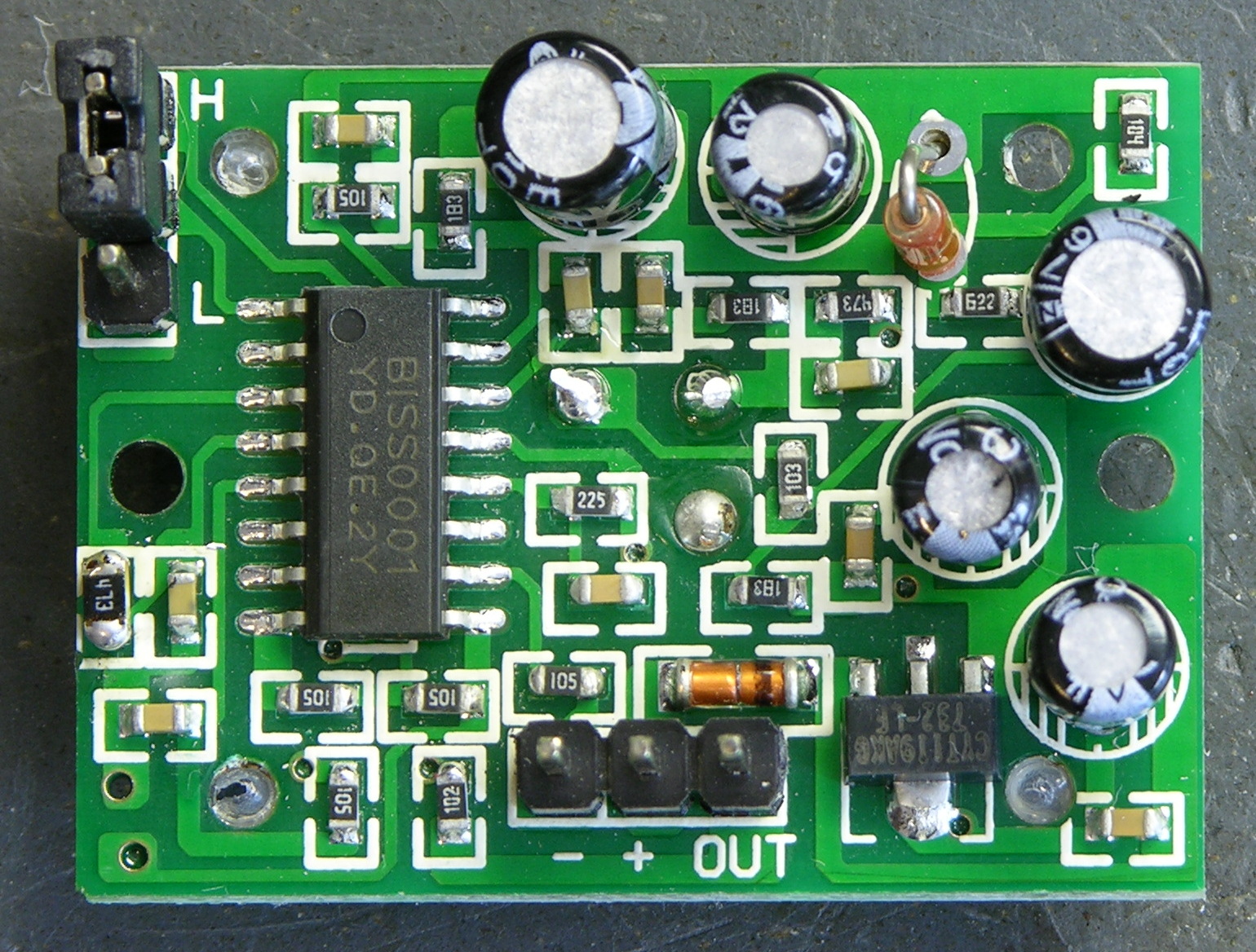
Let’s go back to that component view:
The IC doing all the work is a BISS0001. The only datasheet I can find for it is in Chinese, yay, don’t read that, sorry. The chip has a bunch of comparators, some logic, a logic section labelled in Chinese, and two timers labelled in Chinese. It looks like it’s probably made specifically for motion-sensing applications.
Fortunately the pinouts and component values are labelled in English, so I was able to make enough sense of the datasheet to understand how to set the timing constants. From the sample application circuit, pin 2 is obviously the master output; and on the pinouts, pin 2 is labelled VO.
On the timing diagrams, VO goes high for a period labelled TX and low for a period labelled Ti. Just above that, we have the equation TX ≈ 49152R1C1 leaping out at me from a wad of impenetrable Chinese. On the functional diagram, R1 and C1 stack from pin 3 to 4 to ground.

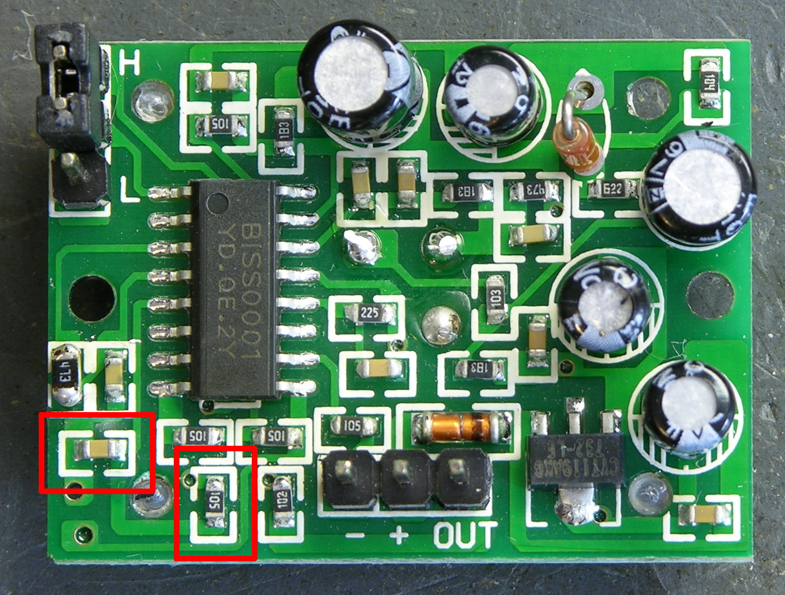
Okay! On the PCB, pin 3 goes to a resistor that said “204.” (Ignore the 473 in the picture.) The resistor and the IC’s pin 4 go to a capacitor, which goes to ground. We’re in business!
The resistor is labelled as a 200KΩ, and my meter confirms that. The capacitor is unlabelled; in-circuit, my meter tests it at about 470pF. Doing the math:
49152 R1 C1 = 49152 * 200KΩ * 470pF ≈ 4.6 seconds
Hm, that’s a little off from the 2.6 seconds I was counting, but same order of magnitude. For a capacitor value that small, I’m willing to believe that I’m getting extra capacitance from my meter probes and from measuring it in-circuit. I think we’re in the ballpark.
The easiest way to shorten the on-period (TX) seems to me to be replacing the resistor. To take the period down an order of magnitude, I should use about a 20KΩ resistor. After looking at the SMT resistors on a dead PC motherboard, I found a 473 (47KΩ) and figured it was enough smaller to make my point.
I desoldered it by wrapping a piece of heavier wire around it and heating the wire, like Josh suggested, and it worked great. Then out of laziness and because the new resistor was larger than the existing resistor and might not fit the pads well, I just soldered it on top of the resistor that was already there, in parallel. Makes it a 38KΩ resistor instead of a 47KΩ, so we’re even going in the right direction.
I powered up the motion sensor again, waited a minute for it to settle down, and started timing its response. On-time after sensing motion (TX) is now in the half-second range. The absolute numbers still don’t match what the equation says I should get, but the relative values are right on — a resistor with 1/5 the value reduced TX to 1/5 of its former value.
Pretty slick! Now I can pick whatever TX I want, be it short or long. I haven’t tried it yet, but the lockout time between motion detection (Ti) is set by R2 and C2 on pins 5 and 6, and they’re easily accessible as well, so I should be able to change that too.
And About that Datasheet . . .
Don’t get me wrong about the Chinese datasheet. Sure I would have been disappointed if I couldn’t read it, but I was actually really pleased that sections of it were in English. I’m aware that people throughout the rest of the world have to learn English in order to do a lot of technical things, and do so with ease and proficiency much greater than that of the few Americans who bother to learn languages other than English.
Bunnie Huang has an interesting blog post that touches in passing on certain types of devices using chips of Chinese manufacture that can’t be found, or can scarcely be found, by searching Google in English:
Just try searching for USB mass storage controller ASICs, or digital picture frame SoCs on Google in English, and then go and open up one of these devices and compare your findings. I bet you’ll find that the chips most frequently used in these popular devices are best searched for in Chinese.
It’s a competitive world out there, and those of us in the west have had it awfully easy for an awfully long time. I know as a mere hobbyist, the technology I use is far behind the leading edge, and I’m not yet impacted in nearly the way of engineers developing new products for market. But the world is changing, no doubt about it, and I hope it’s a while yet before it impacts my ability to tinker.
Good job on this one ! I have a bunch of these and noticed the annoying delays, so annoying that I dropped thos sensors for some projects.
Glad you found a way to overcome this. Thanks !
And good luck with your future chinese lessons
Hello, I have just read this interesting article, Please may I have permission to post this on my website for other ppl to read, as we to would like to try this hack.
Many thanks
Mike
Mike, I’m glad it was useful to you!
I’d prefer you post a summary, possibly with a picture, and link to my article, rather than reposting my entire article on your site. Here’s a nice example of how one site does it:
http://www.electronics-lab.com/blog/?p=1305
Hi Keith,
I am trying to find a motion sensor that could be used to activate a small sound module. This module is contained at the bottom of a small cylinder and I am attempting to find a way to have this cylinder emit sound from the module when it is tilted onto its side.
If you know of a type of device that could work with the sound module then i would be interested in hearing it. I would appriciate any advice you have for me.
thank you
Howard, I don’t know how big a cylinder you’re talking about, but the easiest thing to do would be find a mercury tilt switch. Of course you want to be careful you don’t break it and leak the mercury.
Digi-Key also has several small, non-mercury switches available for $6-8 — one of them might suit you better.
Hope that helps!
This same circuit, or one very similar to it, is used in a solar-security light with motion. It is produced by EnerG+. What I want to do is lengthen the amount of time the security light is on. It is currently on for about 8-10 seconds. I would really like this light to stay on for about 60 seconds.
Even the support from EnerG+ is no help. I am assuming that I would increase the value of the resistor connected to pin 3, but I am not sure. There is a potentiometer on the motion sensor circuit, which is used to control the amount of ‘on’ time, so I suppose I could just add a resistor in series with that.
DJW, when you say “this same circuit, or one very similar to it,” on what basis do you make that claim? Have you seen schematics for the two circuits and they’re nearly identical? Does your solar security light also use a BISS0001? If so, then you likely could change the resistor attached to pin 3 of the IC.
But since there’s already a potentiometer to control the on time, I’d suggest having a look at that. See whether it’s really being used as a pot to set a control voltage, or whether it’s being used as a variable resistor in the timing circuit. If the latter, swap it out for one with 10x the value and you should probably be in good shape.
Hi Keith,
First of all good job! I’m really new to electronics in general but I would like to use this sensor to switch on emergency lighting (which automatically come on when there’s a power outage) for a couple of minutes only when motion id detected, rather than have them on all the time and quickly rub down the batteries. Do you reckon that’s possible?…and if yes can you give me any ideas for how to do it?
Thanks a lot, Keith
Lawrence
Lawrence, my approach would depend on how much light I wanted to provide and what materials I had on hand.
I can tell you that I would definitely start with an existing emergency light system — I have no desire to take engineering responsibility for a gel cell charging / charge maintenance circuit. I’d dig in and see how it turned on the light — relay? FET? something else? — and then look at integrating the motion sensor’s output into that control line.
It’s hard to say much more without having the emergency light circuit in front of me, because it could go so many different ways.
Hi Keith, thanks for your prompt reply.
I guess I understand what you are saying. I’m figuring the sensor can go somewhere between the supply and the switching device. Obviously I’ll have to increase the on time to about 2/3 minutes or so because they’ll be in an 4 floor apartment staircase.
Well I’ll have a go at it some time soon.
thanks again
Lawrence — specifically, I assume there’s already some kind of (relatively) high-current switching device turning the light on and off. I’d look to inject the motion sensor’s signal into the control side of that switch (relay, FET, whatever) so it can still do the job it was made to do, just with additional input.
Hi Keith, thanks once again for your input. I guess I’ll open up one of the lights and see what I can do. Like I said I’m a newbie so I’m a bit weary of all this, still I’ll have a go and then I’ll send off for one and give it try.
Thank you very much for your extremely informative article
I’m trying to determine how to use pir in a small low voltage circuit to detect presence rather than motion.- What I need to do is trigger a pulse when presence when the presence is no longer detected. badically i need to close a circuit momentarily when a small room ( a living room for example) is no longer occupied. I need to ensure that this ‘event doesn’t occur when someone is simply setting still on a couch not moving. How would you accomplish this?
Sean, I think there are “pyroelectric” sensors that will detect the infrared heat signature of a human body and tell you about its presence, not its movement. I don’t think you can (easily) hack a PIR motion sensor to do that, but try searching for pyroelectric.
Hey Keith,
Great info on the PIR, thanks. I have one very similar to the Parallax unit (it has minor differences like no jumper for changing the re-trigger mode), based on the BISS0001 IC. I’d like to be able to adjust the time between triggers (Ti) by using a potentiometer. You touch on that possibility in the above article, and I was wondering if you’ve had a chance to try the hack yet.
I was looking for sites on pir’s and found yours. I’m not famular with this much but thought you may help. I want to put a pir on a usb and plug it in to my computer. Why? Well I don’t know for sure but thought it would be nice to see what it reads. Does this make since?? I want to make a sensor that triggers a response and a program that reacts to it. (using usb cable or blue tooth). Thanks
Denis, I don’t know what to suggest for the computer interfacing part. It’d be easy to hook any sensor to an Arduino and have the Arduino talk to the PC over its USB-serial driver, but that’s going to add quite a bit of expense to your project.
I am ok with any value for Tx. I want to remove Ti value. Is it ok to make Ti value 0? is it possible?
Vikas, I don’t know whether you can set Ti to be 0. You should certainly make it much shorter by changing R2 and C2, as noted above.
Hi
I am so glad to find some one who has a good information about motion detectors
my quistion is
I have a project of (how to control surveillance camera using a motion detectors)
so can u give an informations can help me in my project?
Because its my first time working in motion detectors so i dont have enough informations so can u help me?
I will be so glad for ur helping
Hi Keith
I am so happy because I find someone how has a good background about PIR.
My question is I have a project about how to control a survillence camera by PIR so I dont have any information of PIR and how I can make it to control the camera so can u help me in this?
I will be so glad if u help me.
Amr, what kind of control do you want?
Thanks Keith for reply
revolving camera attached to stepper motor controlled by PIR
Keith the control that I want is to connect the PIR to Stepper motor to revolving the camera to the direction where there is a motion.
So do u get what I want?
So please can u help me in this.
I will be glad if u help me.
Amr, that’s a hard problem to solve. You can’t have the motion sensor on the revolving platform, because then it would detect motion all the time. You can’t use a single stationary motion sensor, because it will simply tell you when there is motion within its area of view.
If you wanted to use PIR sensors, you would need to build a ring of them, each with a narrow view, and then point the camera to where motion just occurred. I suspect this is not practical to do.
I believe real motion-tracking cameras use background-delta image-processing algorithms to find the motion.
Thank you very much Keith for your useful advice its almost what I intend to do
thank you
Hi Keith,
I am looking for some sort of a sensor (capacitance sensors?) that can detect movement behind an opaque surface (such as a closed door). Any guidance on what I should look for?
Thank you,
Satish Menon
Hi Keith Neufeld,
I found your article very interesting. I have a question, is it possible to Detect “ONLY” human beings’ motion using PIR sensor?
Since it is used in Burglar Alarm system, it shouldn’t get triggered due to movement of other living beings like say, cat, dog etc as these animals too emit IR.
Is it possible to eliminate IR from other animals using filters? I am not sure of the frequency of IR emitted by Human Beings and other animals.
Please enlighten me in this regard, Waiting for your reply….
Hi keith,
Good knowledge of the pir i must say..really impressive..I would really appreciate if you can help me on this…I am using a PIR detector to control a siren via a relay, but what happens is initially when the pir is triggered, the horn works perfectly, on the third trigger, the horn remains horn without going of..the output at the pir remains hi instead of going off when the motion is no longer sensed…Have used two different pir detectors and the output is the same..pls advise
Hi keith
how r u?
I need your help again to answer this question
I have a continues 5v DC signal and thats the output of the PIR that I have it I want to make it a pulse signal not continues to make the servo motor revolving to the position where there is a motion so what is the circuit that can help me to convert the continues signal to pulse and controlling the time of the pulse
so please keith I need your help in this
Hi guys,
this is really great artical and it is really helpful. Great job! I was wondering what would be your suggestion what should be changed in the PIR curcuit to be able to change sensitivity?
Thanks!
Hi, I’m horrible with this kind of stuff, but I have one of these and I want to hook it up to a small buzzer. I’ve tried hooking it up on a breadboard and other things, but I suppose my connections to the sensor are not right. If you could perhaps help tell me what to do, It would be more than appreciated. Thank you very very much.
Danny, the sensor won’t have the current capacity to drive much of a buzzer — you’d need to have the sensor power a transistor or small relay if you want it to activate a mechanical buzzer. It might be able to power a piezo buzzer — but some piezo buzzers require an active oscillator circuit to operate, so that’s also a little more challenging.
Hi Keith,
The question is not related to the article as such. I am researching on using a single PIR sensor to trigger multiple sounds. I wanted to know if that is feasible in the first place. If so, then how can I get the sounds to play sequentially using different triggers for each sound.
Dee, a single PIR sensor doesn’t provide different outputs. If you want sounds to play sequentially, you would need to either use an external means of sequencing them after a single motion event or use multiple PIR sensors connected to the different sound players.
So if you can’t make it work with a buzzer, how about a light? If not, what’s the point of this thing…?
Thanks again,
Danny
Danny, you can make it work with a buzzer by using a small relay to interface between the low-current, logic-level signals of the motion detector and the high-current, probably not 5V drive of the buzzer. You’d need to do the same to drive any light other than a small LED.
Hi Keith,
Do you see any way to hack the PIR to deliver different voltages based on IR intensity? I’m hoping to build a cat-chasing robot that would use two PIR detectors at slight angles with a divider between them to somewhat separate the visual field. But the on/off values are annoying. I’d like to be able to triangulate.
Any ideas?
BTW, I’m also in Kansas, though in Overland Park instead of Newton. My great uncle was from Newton, though.
Kathryn, great to hear from you! I remember seeing a presentation of yours at CHECK a few years ago, probably when it was hosted at KU, and I think visiting with you a bit after the talk.
The best datasheet I’ve seen for the BISS0001 IC is hosted at ladyada.net. Although the block diagram looks as though the internal OP2 is being used as a comparator, the fact that it’s followed by COP1 and COP2 in a window comparator configration makes me think OP2 is just being used as an amplifier.
OP2′s amplified output is available at pin 12, and the application example circuit looks identical to what I see on the Parallax PCB. So it looks to me as though you could pick up an analog version of the PIR sensor’s signal at pin 12.
I’d want to test this with an oscilloscope before staking a whole project on it. Do you have a scope, or should I make time to try this out? Once we know, you could solder a fly wire onto pin 12 and break it out to an analog input on your Arduino. Or, seeing the remark on your blog about soldering skills, I’d be happy to solder for you.
Yes, it could have been at KU, KUMC, or Washburn. I gave several. I never assume anyone remembers me. I’m no longer at KU since management there went crazy. I’m self-employed now.
Thanks for the info. I don’t have a scope, unfortunately. My soldering skills will come back, but I may take you up on that.
BTW, the current version of the Parallax PIR has a pot to adjust the timing.
I’m mocking this up on foam core before I build anything that will withstand a cat’s paw knocking at it. For the final, I’m thinking aluminum chasis, possibly from chasis components from VEX.
When the code is a bit further along, I’ll deploy it to my github site.
Keith, I recently picked a PIR sensor at radioshack as well. Not the parallax Sensor, but a Talking Pumpkin insert (radioshack sku 630-0282) on clearance for 97 cents (1.00 after taxes). It has the same biss0001 pir ic, and a comparable PIR sensor (I think). Much better than the 10 for the bulkier parallax module. No through hole parts, all smd. The size of a quarter, in a small case with a wire going to the main body of the toy.
Basically, if something triggers the PIR sensor, it plays spooky sound effects and lights up a pumpkin. Plenty of space to add another microcontoller really.
Anyway, just wanted to point out, that when I was finding info on the biss0001, the datasheet I pulled up, which is apparently the same datasheet ladyada has that you found, the TX formula is actually 24576*R1*C1 (or otherwise labeled resistor and cap coming off pin 3), not 49152. You were doubling the result, which is why you got 4.6 seconds instead of the 2.3 seconds that it was actually triggering.
On replacing it with a 38k resistor, you turned it into a .43 second trigger.
Ti is the same, 24*r2*c2.
cde, LadyAda found a much nicer datasheet than was available online at the start of 2008. I looked again and the datasheet I used clearly says TX ≈ 49152R1C1. Thanks for the note — it’s nice to know the datasheet was just plain wrong!
Could be that the Chinese datasheet was for a different revision of the biss0001?
Hi keith, I would like to know how to narrow the field of view ( if possible) to approximately 5 deg. or even less. I am a little confused.
Can I intervene on the spherical fresnel lens ? Can I build a new lens ?
why is the spherical lens cut up into zones ?
Thanks , Dino , Italy
Hey Keith,
Great post.
Stupid question: Is there a way to limit the sensing range to a maximum of about 3-5 inches? I was hoping to find some information on small range sensors that you find in the “motion” triggered sinks in public bathrooms, but there is so much more info out there on these little Parallax guys I’d rather use these.
Any suggestions? Thanks in advance.
Addison, those are actually proximity-triggered, and you can buy the Sharp IR sensors from Acroname. They’re affordable and fantastic and they work (for me) way better than the motion sensor!
Hello Keith,
Do you have any good links or information related to testing PIR and/or IR sensors? I am trying to come up with a way to measure the intensity of an IR signal and also perform functional tests. After doing some research I’ve come to the conclusion that there are a lot simple ways to do this. However, repeatability, cycle time and minimum space is important which is solved with an intelligent automated test. A high level idea I have in mind is to enclose the sensor and introduce different lux levels of light to increase light intensity. At the same time I would introduce a mechanical movement at a fixed distance from the sensor. Another idea is to enclose the sensor and introduce mechanical movement with some sort of heat signature on a lever attached to a servo, maybe a resistor? The only question is; how can I attenuate the IR beam to somehow increase the distance from the sensor to the object without physically move heat signature?
Hi Keith,
I read through your article and comments as well, but didn’t find why it is called ‘human body detection’ tool (if the link si the same: <sales link redacted>)
How this sensor differentiates cats and humans? Simply it depends on the sensivity range? Do you have info of that?
Zoltan, I don’t think this sensor differentiates between cats and humans. If it were to do so, it would have to be based on the specific infrared frequency of heat emitted by humans, and I don’t think this one is that sophisticated.
Has anyone come across a maximum Tx on the BIS0001? I had a similar setup with a 90 sec Tx and I doubled the resistor on R1, with no apparent effect. Any suggestions on how I could extend Tx beyond that?