I still want to find a small LCD module for the LED calculator, so I can fit the whole thing into a box with a footprint about the size of a deck of cards. But for prototyping, I have a stack of 2×16 LCD modules about 3 1/2″ wide (viewable about 2 1/2″) from Slim, and Wednesday night I got one hooked up and working.
They’re Optrex DMC-16207 modules, and they seem to be using the Hitachi chipset that everyone uses, or at least an equivalent, although I didn’t know that at the time. Searching online, I had a hard time finding data on this exact module, but came across a mechanical drawing, a module user’s manual, and finally a full datasheet.
Interfacing the Arduino and LCD
I dived in and wrote my own LCD interfacing code. I found out in retrospect that there are several other Arduino LCD interfacing projects out there:
But all of them are using hard-coded delays to pause while the LCD processes commands, rather than checking the busy flag. To be sure, I’m doing the same thing right now in my first draft of the code; but I’m going to go back and clean it up to do it right.
Also, I haven’t checked all of them, but at least one is using digitalWrite() to manipulate each bit of the port register individually. Since I’m dedicating eight Arduino lines to the LCD’s I/O port, I can write the port register as a byte rather than twiddling individual bits, saving time and effort.
My goal will be to write a nice library module/class that encompasses these different approaches (8-wire vs 4-wire, busy flag vs hard-coded delays, read/write interaction vs hardwired write-only) and presents a clean interface to the programmer to select the options. Of course, for now, I just wanted to get it up and running.
I found this ATmega to Arduino pin mapping, which confirmed that Arduino digital lines 0-7 are PORTD lines 0-7. And the Arduino port register reference shows that DDRX and PORTX are defined as Arduino variables; so writing to a port is as easy as PORTD = $ff . It’s very nice that they left those low-level features exposed, even though in most cases it’s better to use the higher-level interface for portability.
Calculator Prototype
So here’s the work in progress.
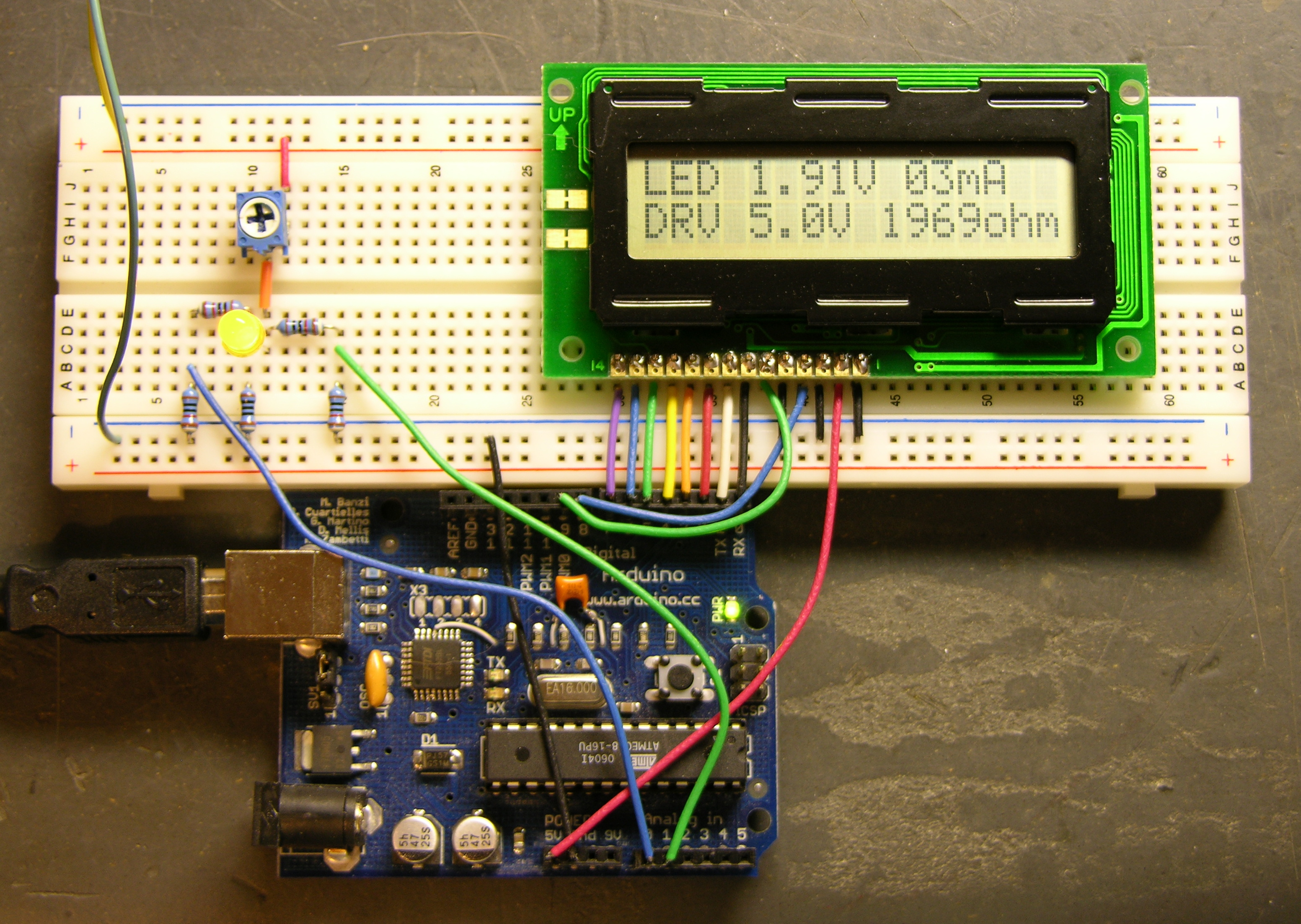
The Arduino is getting power from USB and supplying 5V power to the LCD. The LCD contrast is hard-wired to ground. Although it actually looks pretty good right now, I’ll want to put in a potentiometer to adjust contrast. And I’m still using my bench power supply to run the LED circuit at 9V.
I don’t have a method built to select the voltage of the target circuit — the software is assuming 5V for now. The easy thing to do would be pushbuttons to bump the desired voltage up and down. It’d be kind of fun to do it with a spinny-wheel, although I’m not sure how much that would increase the cost, and I’m concerned about overengineering this thing if I really want to offer it as a kit. Maybe another potentiometer is a good compromise.
However the target voltage is selected, I need to determine the selectable range (which could of course be overridden by an owner with an AVR programmer). I’m thinking 3 – 15V in .1V increments. Is that enough?
If you’re still looking for a small, text-based LCD module, you might try all electronics: http://www.allelectronics.com/cgi-bin/category/365/LCDs_(Liquid_Crystal_Displays).html
They have a good variety of surplus HD44780-compatible LCDs at the best prices I’ve found. I even used their “lcd-107″ on this project: http://cheaphack.blogspot.com/2008/01/turing-alarm-clock.html
Nick
Nick, I had looked through All Electronics’s offerings, and they don’t have anything small enough to fit across the short end of a deck of cards, my target size. I may not be able to get quite that small, but there’s an LCD screen close to that at Digi-Key for only $5.88 that I plan to try.
I like your alarm clock, by the way. Looks like fun!
Hi …I have a clock/thermometer with 3 1/2 LCD displey and I would like to know how to change the displey with 3 1/2 LED.Could you help me with these project.
Thank you George
George, I’ve looked into 3 1/2 digit LCDs a little, and as far as I can tell the LCD driver is always integrated into a monolithic chip performing the device’s main function (meter, clock, etc.). That makes it not at all easy to swap out the LCD for LEDs. Sorry.
Keith,
I’ve put together a comprehensive LCD library for these hitachi based screens. It supports both 4 and 8 wire mode and all pin mappings are customizable without modifying the library code. It even supports defining custom bitmap characters in the LCD’s character ram.
For now the code lives on my site, but one of these days I should move it over to the arduino playground.
http://www.slashdev.ca/arduino-lcd-library/
hi..i want u to help me..i have to do a project about simple calculator using Motorola 68K(Easy 68K Assembly/Editor)..I have 2 weeks more to finish my project..the input for my project is by using switch in arithmetic operations which are add,subtract and multiply..I hope that u can help me..thank u very2 much..
Halida, are you asking me to help you cheat on a school assignment?
Are you aware that:
Please, think very hard about doing your own homework. If you don’t enjoy electronics and software development enough to write your own homework programs, is it really what you want to make a lifetime doing?
help me how to design a random flasher display unit of acalculater. thanks
Henry, what would be my motivation in doing that?
Did you ever finish your LCD module library? Or find a suitable LCD display module? I’m just starting to play around with an Arduino for a project I had in mind, and I’m looking around at various display and casing options. What were you thinking of using for a case?
CAN I USE ANY 16*2 LINE CHARACTER LCD WITH THIS CIRCUIT
Any with the Hitachi driver/interface IC, yes.
why only Hitachi driver/interface IC and why not other one’s
Because the Hitachi driver (or compatible) is used in 99+% of the alphanumeric LCDs in the world (I don’t even know of other drivers) and I don’t have any LCDs that don’t use it.
OK
AND CAN YOU SEND ME THE CIRCUIT DIAGRAM OF THIS PROJECT WITH
ITS CODE AND OTHER IMPORTANT THINGS ON MY MAIL ID
The circuit diagram is already available here. The code, no — it’s not complicated, and if you’re interested, it would be a good exercise for you to figure it out.
I CANT UNDERSTAND IT PROPERLY
I PRACTICE BY UNDERSTANDING THE ON PAPER CIRCUIT DIAGRAM
AFTER THAT I CONSTRUCT THE PROJECT AND PLEASE GIVE ME CODE
SO THAT I CAN KNOW HOW IT WORKS AFTERWARDS I WILL MAKE MY OWN
AFTER STUDYING IT
OK….
ok i got the circuit diagram and only please give the code