An Arduino “shield” is a PC board made to plug into the top of the Arduino, covering it (hence the name) and extending the Arduino signals to provide some extra functionality. Shields I know about are prototyping shields (“protoshields”), with a tiny breadboard on top; motor control, with H-bridge drivers to run motors, servos, and steppers; and ethernet, with a Lantronix Xport ethernet interface onboard. (I know there are shields from places other than Adafruit, but I really like supporting Lady Ada’s open-source hardware lifestyle, so I tend to look there first.)
After getting my Arduino, I had thought about getting a protoshield, but dismissed it pretty quickly — it seemed to me that the tiny breadboard on it would be too small to be useful for anything complex enough to be worth using the Arduino for. But Friday the Arduinos arrived for class, I agreed to do a demo/intro on Monday, and I realized it’d be a lot easier to do on a protoshield than on a separate breadboard.
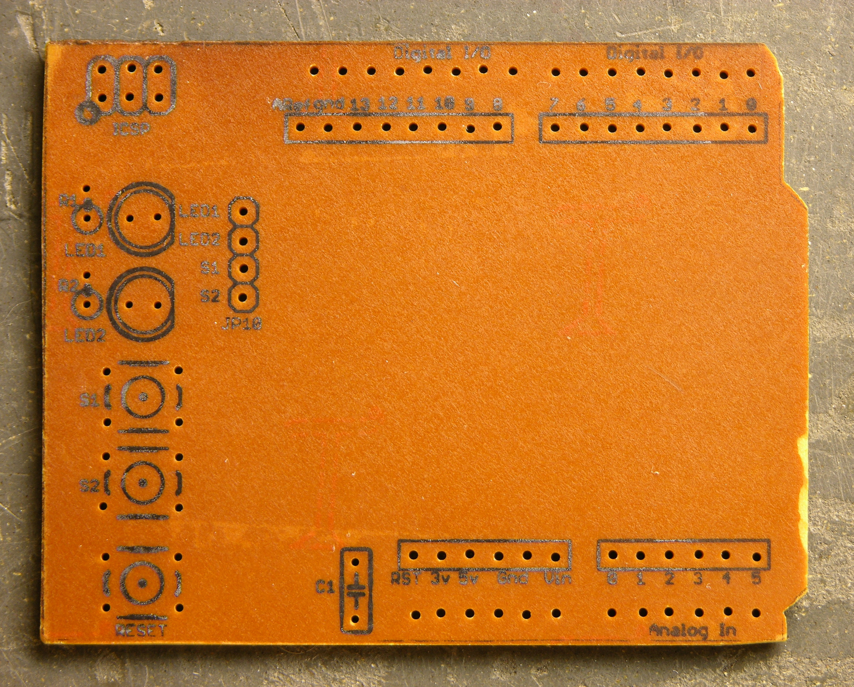
With no time to order one before Monday, I had to construct my own over the weekend. I started with Lady Ada’s EAGLE schematic and board files (Creative Commons 2.5 Attribution Share Alike) and hacked them up for a single-sided board that I could etch quickly and easily. I took out her solder prototyping area, moved headers to align better with my tiny breadboard, changed up the LEDs and pushbuttons, and generally did enough work that I’m not sure I saved any time starting with an existing design. ![]()
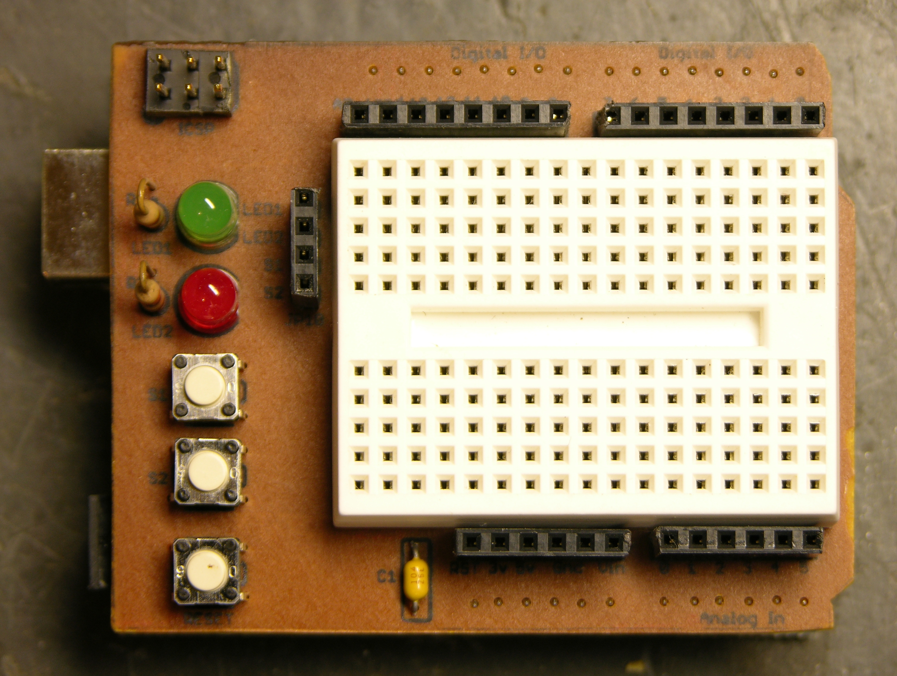
Here’s the result — ugly but very functional. I generally use breadboard wires cut and bent to length, so it matters to me that the header sockets are aligned with the breadboard columns and spaced a multiple of .1″ away. It works out very nicely.
Silkscreen Toner Transfer
Worth noting is that I used Cort’s idea of iron-on toner transfer for the silkscreen layer on the top side of the board.
After the copper is etched, the etch resist cleaned, the board tinned if you’re tinning, and the holes drilled, you print the silkscreen layer and do an iron-on toner transfer just like you would for etch resist. The main difference is that for appearance’s sake, you really want to get all the paper fibers scrubbed off of the toner — I probably spent half an hour in the sink with the toothbrush getting it clean.
I think the method is great; it’s just this instance that’s less than perfect. For one, this PCB is very dark, and the black toner doesn’t show up well; it’s much more readable on lighter boards. For another, the font is really smaller than is advisable for a toner transfer — I’m surprised it actually worked as well as it did.
It’s a very nice change to have labeled connections on a homebrew PCB.
Using It
I practiced my spiel tonight for class tomorrow, starting with the Arduino “Blink” sketch flashing the onboard LED, then:
- plugging in the shield and jumpering in the green shield LED to blink as well
- jumpering in the red LED and updating the sketch to alternate green-red-green, etc.
- plugging a common-cathode RGB LED into digital pins 9-11 and updating the sketch to alternate red-green-blue-red, etc.
- writing a
pulse()function that usesanalogWrite()(PWM output on pins 9-11) to fade an RGB color from dark to bright to dark and updating the sketch to pulse red-green-blue-red, etc. - wiring three more pushbuttons to digital pins 0, 3, and 6 (LOVE the ATmega’s internal pull-up resistors!) and changing the sketch to pulse a color dark-bright-dark on demand
It’s all pretty easy stuff, so the idea is that I’ll be able to do it while maintaining a stream of patter. We’ll see how that works out. ![]() Still, it’s a nice introduction to a few of the capabilities of the Arduino and to how easy it is to just try things when you have a breadboard and a nice microcontroller development system.
Still, it’s a nice introduction to a few of the capabilities of the Arduino and to how easy it is to just try things when you have a breadboard and a nice microcontroller development system.
So Do I Like It?
Using the protoshield tonight has convinced me that it’s great for a tiny demo, and too small to be useful for real work. ![]() I’m not complaining, though; it’ll be fun to have around.
I’m not complaining, though; it’ll be fun to have around.
One thing that would help is the addition of a ground bus at the bottom — I waste a lot of column space leapfrogging ground to everywhere I need it. There’s room on my board that I’ll add a ground row on V2.
Credits
Original shield design by Lady Ada
Tiny breadboards from terminalcity
I don’t think it is very ugly! It has a certain character to it, yes. Nice work. Good for quick and easy tests and trials, i would imagine.
Thank you, Sebastian. Perhaps I should say it has a great personality?
You wanna see ugly, come back in about a week. I have something up my sleeve . . .
Yea, that looks awesome. Very nice retro / futurist style.
How did you solder the pins on the other side? I’ve been wanting to do this for ages on single sided stripboard.
Nice board too by the way.
Adrian, it’s embarrassingly simple — slide the plastic strip to the wrong end of the pins, solder them carefully, and push the plastic strip back down as close against the solder as you can.
Keith,
Nice board! I’ve been wanting to do a single PCB sided proto shield myself. Do you have your modified EAGLE schematics available for download somewhere?
Josh, thanks for the compliment!
I haven’t posted the schematics and board layout yet, because I want to get header strips added for a ground plane and probably +5V plane as well. Shouldn’t take me long to do that if there’s interest, and I can post an entry here when they’re ready.
Are there any other changes you’d be interested in? Or do you want the single-sided design as a starting point for your own board; and you’re going to hack it up anyway, so my changes are unimportant?
I don’t plan to change anything, I’m just happy to have the small breadboard and headers for small projects. I’ll wait till your finished working on it…
Awesome, thanks for the heads up, thats really gonna save me a lot of hassle.
I built my first pcb the other night. The board went well despite printer trouble. My toner has been running low for a while but I wasn’t worried as I had another one in the closet. I dropped it in right before doing my board and found that it was a dud. It had been sitting in my closet for a while and wasn’t applying toner at the saturation levels it was supposed to so I had to run my pcb through the printer 3 times so that’s why my traces are so nasty. The circuit is super super simple, but I just wanted to print something.
Anyways, I know what you mean about wanting to get all the paper off for your silk screen. If you don’t you get this weird blue/white color after it dries. When it is wet all looks great. So I was afraid that if I rubbed too much I would loose the toner and with it the whole purpose of the silk screen. So I went to my kitchen and grab some vegetable oil and applied it to a q-tip and lightly swabbed the printed areas then removed the excess with a cotton cloth. I got enough of the oil off so that you don’t notice it on your fingers after touching the board. It worked perfect! Many days later the silk screen still looks crisp black. I think next time I will try to use mineral oil or lynn seed oil. Either way I would recommend a small application of oil to save excessive scrubbing. Next time I also want to try applying a thin coating of hair spray to see if that will make the toner stay that dark color and make it more difficult to be scrapped off. Though once you solder on the components the scratching and flaking is less likely.
I think when I do a board with traces that are closer to each other I may even attempt a solder mask to prevent the solder from flowing so much. I think I’ll try just toner transfer for that as well but I’m not sure.
Sorry wrong link above to the toner transfer silk screen pcb. Here is the corrected url, http://flickr.com/photos/paretech/2707568690/
Matthew, a couple of notes about your iron-on solder mask idea.
First, I’ve tried ironing “silk screen” toner transfer onto the copper side, and it didn’t work well for me. The toner didn’t seem to stick well to the copper, and it didn’t stick at all near the edges of traces. I ended up wiping it all off and lettering by hand with a Staedtler pen. So I’m not sure the iron-on technology is going to work well there.
Second, thermoplastic laser printer toner isn’t a good choice for a solder mask — if the household iron melts it enough to stick to the board, the molten solder is going to melt it enough to unstick. I’ve thought about doing something like a toner transfer for the solder areas, then spray on varnish, then scrape off the varnish and toner, but that’s not exactly . . . elegant . . . or efficient. And I’d still have the problem with the toner not sticking well on the copper side in the first place.
I’ll be very interested if you come up with a good way to do this. Well, even a way that works at all.
Well I’ll give it a try on my next pcb. The whole reason I even wanted a solder mask was to try to deter the solder from flowing on the traces. The pcb linked to above was my first attempt but there were several issues that I noticed along the way.
Staples was kind enough to replace a “stocked” toner cartridge that I had sitting on my shelf for three years! They just gave me a new one and let me go out the door, which was totally unexpected but totally cool of them. So I expect finer traces and cleaner results for my next board but I think I will still try a solder mask. It doesn’t need to be perfect and I’m not too worried about the toner melting as I think it will create enough of a lip to create enough surface tension for the viscous molten solder to stay put. Though it may look a little nasty colored as I don’t think I will be able to remove all the toner once components are placed on the board, but I think that is a fair trade for cleaner solder pads and traces not bleeding with copper.
I use “Staples Photo Basic Gloss” paper as recommended by the GoTee method and I had really low expectations for the entire process especially after I ran into printer trouble. I found that you don’t have to heat the board for nearly as hot, long and with such pressure as the method recommends. Just long enough and hot enough to release the toner and not necessarily to melt the paper to the board. I found patience to be the biggest determiner for how well the toner transfers to the board.
Anyways, I’ll be back after my next board. I have a socket iWiFi card that I would like to make a shield for my Arduino BB. BTW, just salvaged a 2×40 LCD out of a junk box and it works perfect. I’m currently working on writing a “Menu API” for HD44780 compatible LCD drivers to make devices with a UI faster to develop and implement.
Cheers,
-Mpare
hey ive been hunting everywhere for those small black pieces that you use to connect the wires. could you please tell me what they r called and perhaps where you got yours? shoot me an email if you dont mind xxsupraman888xx@aol.com
Robert, search Digi-Key for “female header”, click “Rectangular – Headers, Receptacles, Female Sockets (8,375 items)”, and select .100″ pitch, 1 row, Through Hole mounting, and In Stock. (I can’t give you a deep link into Digi-Key’s search.)