For Friday’s show, we used Alesis monitor speakers that we had in the lab, plus Steve, one of the students, supplied two.
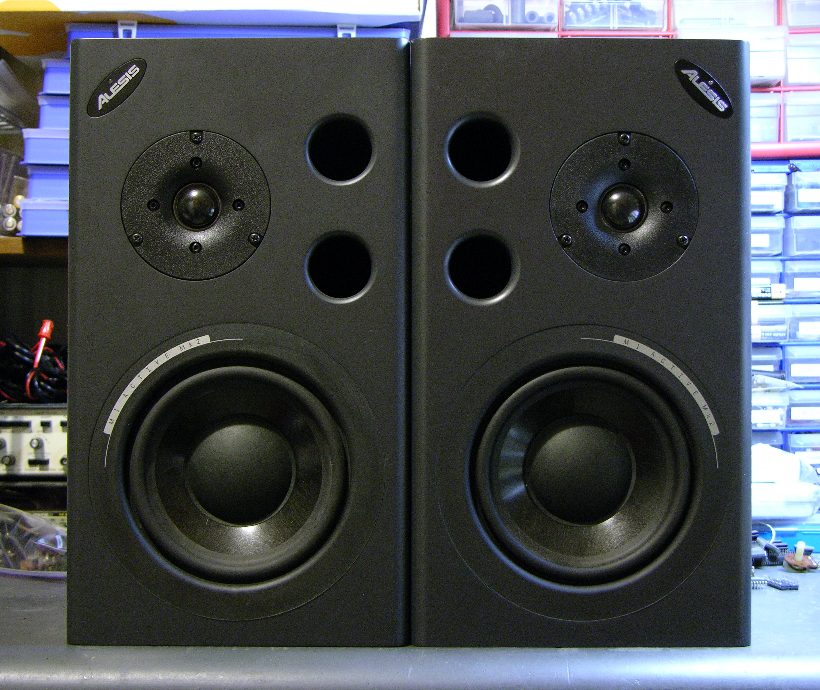
During installation, one of the speakers started winking its blue power light and ceased playing sound, and before the show another did as well. Steve found a Studio Central forum post suggesting that the problem was due to a failed electrolytic capacitor that gets baked by a hot resistor right next to it, and a quick peek inside confirmed that it was a likely explanation and fix.
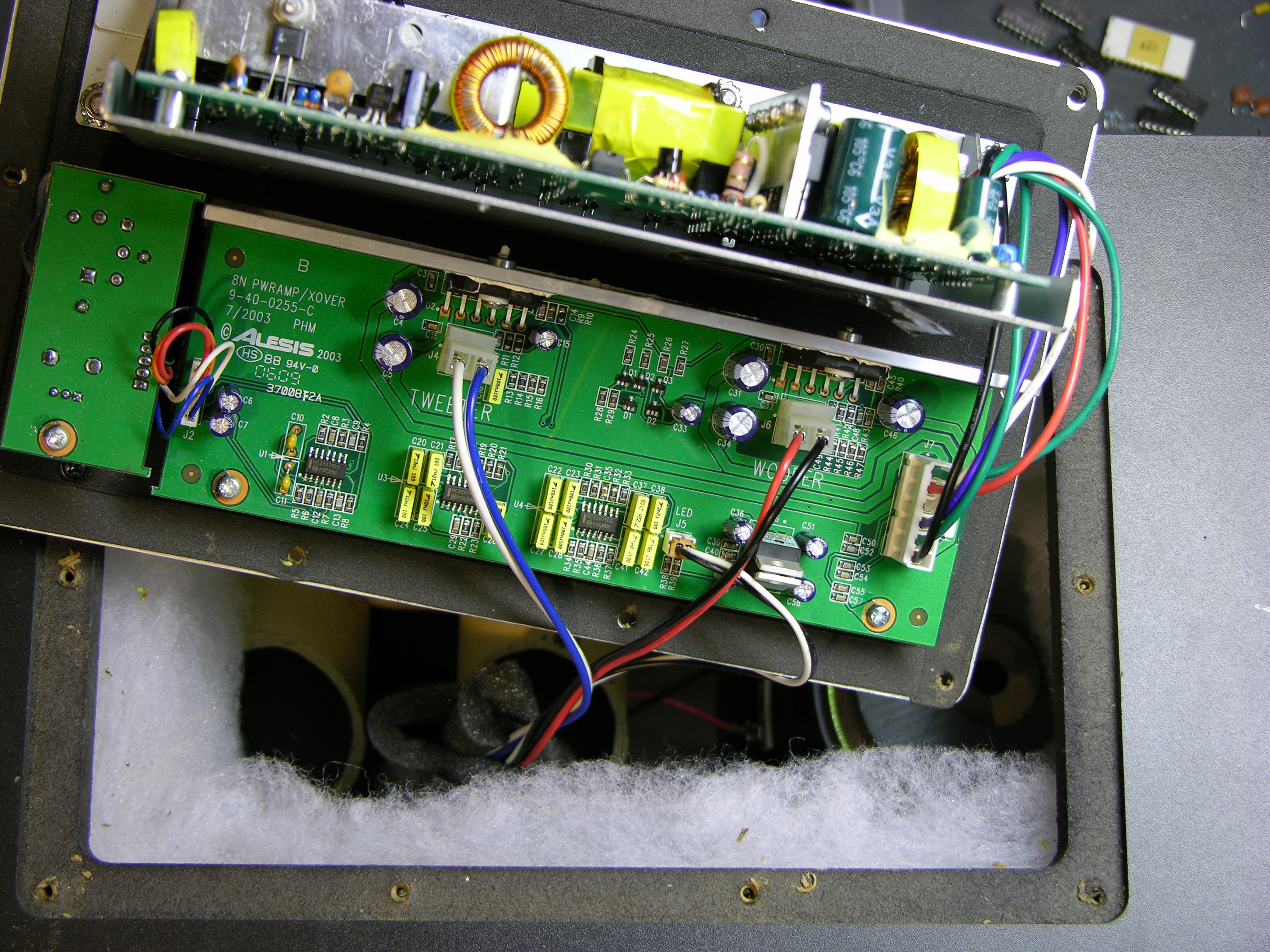
After unscrewing, the back panel lifts out and reveals the power supply board mounted vertically on a metal shield, and the crossover/amplifier board mounted flat on the panel.
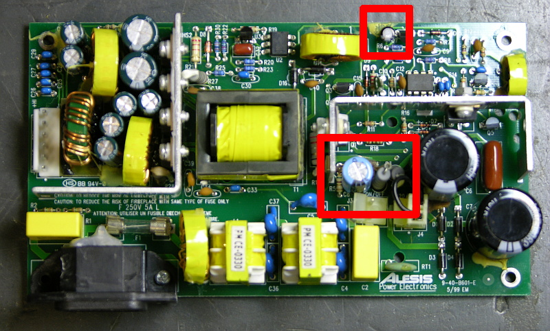
The naughty capacitor, C8 (actually its replacement after I finished), is in the center red rectangle next to the offending resistor. Another bad electrolytic capacitor whose number I forgot to catch is featured near the top of the board. Both of these tested bad with my Capacitor Wizard in-circuit equivalent series resistance (ESR) tester; all of the other electrolytics on the board tested good.
It was simple work to remove and replace the two capacitors on each board, and it brought both speakers back to life. Thank you, forum posts and Capacitor Wizard!
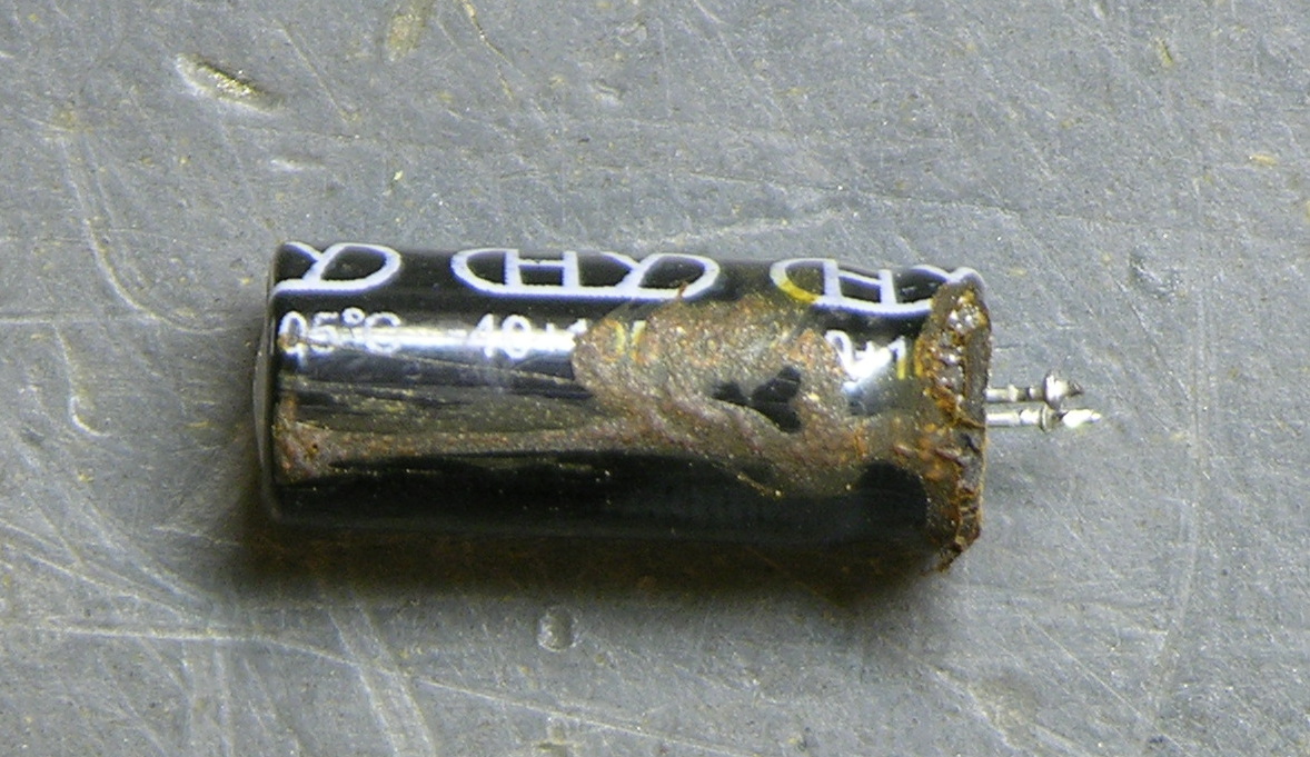
BTW, are electrolytics supposed to look like this?
Two caveats about this repair. First, I should have used 105°C capacitors, but I could only find 85°C caps on short notice, so these will fail quickly and need to be replaced again. At least now it’s known exactly what needs to be done. And second, the forum post suggests moving either the resistor or capacitor to get them further apart, which is a great idea but which I haven’t done yet. I’ve been trying to think up a clever way to stick a little heatsink on a vertically-mounted resistor, which might be a better solution yet.
Chris, I haven’t reverse-engineered an Alesis power supply yet, so I don’t have a definitive answer. But from what I’ve seen recently of off-line switching power supplies, my hunch is that at least the FET that switches the transformer primary is blown, and quite possibly other closely-connected components. And you have to get them before powering up or it’ll keep blowing the ones you’ve already replaced.
If you end up replacing the power supply board and you don’t have to return the failed one in exchange, I’d actually be a little bit interested in taking a look at it. I’ve never personally applied a wrong voltage to a device and I’d be curious what the consequences are. But if you’re saying it was supposed to be on 220V, you’re probably outside the US and shipping might not be economical?
Tiago, I haven’t traced the circuit and I don’t know whether you’re likely to have just a bad LED or whether it’s indicating something else wrong with your speaker.
Do you have electronics experience? I would take a 9V battery with a 1kΩ resistor and test whether the LED still lights. If not, it’s just bad and replace it. If it does still light, the problem is elsewhere and do more investigation about what’s really going on.
Hello Keith
I don’t have much electronic experience.
Yesterday, I tried to move on the wires near the light and I saw that the Led lights, then it is a bad contact. Can you tell me if this led have more functions apart from this report that the speakers connected?
I saw that in the speaker on top of the led has a lot of silicone, I do not know how to remove the silicone to resolve the bad contact.
Thanks a lot, Tiago Barbosa
Tiago, try to find the loose connection by paying attention to what wiggling makes the LED light. Then cut and scrape the silicone away from that area, resolder the connection (or find someone who can help with that part), and you should be in good shape.
Hi, I had this problem some time ago, both monitors would flicker sometimes when you turned them on, and other times they would turn straight on. When we opened it up we noticed that the capacitor C8 (220uf 35v 105c), had started to pop a little. That was replaced along with the resistor R4, and when we reloaded the speaker it worked fine, now I got to do the left channel now.
Keith you deserve a medal, sir!!
I thought I had slightly misplaced optimisim trying this. But similar to other posters I watched a few videos on Youtube, took a deep breath and started soldering things.
I have no ability to test the capacitors so I just replaced the same capcitors as you. I now have perfectly functioning speakers again, gained from the confidence and instructions on your blog, and am a very happy man.
Thank you.
Matt, delighted that worked out for you!
Don’t forget to give credit to the Studio Central forum where I first found how easy these are to fix. I’m sure they’d appreciate the props as well!
Maybe a possible fix would be to use wirewound resistors, so they will take the heat better?
Steven, I’m not sure that wirewound resistors would do any better for the heat. The heat is a factor of the power dissipated across the resistor, which is the same regardless of composition. The only difference I can think of is increased surface area to provide greater area to dissipate the heat.
Also, I haven’t drawn out the schematic of the power supply — and I do intend to this summer — so I don’t know yet what role that resistor plays in the circuit. There are some places in a switching power supply that the induction of a wirewound resistor is unacceptable, so that may or may not even be a possible substitution. Just something to think about.
It’s great to be considering alternative approaches to solving the root problem, though!
I was thinking that if you use wirewound resistors, you would have the ability to place a small heatsink on it to help dissipate the heat even better. As the resistors that are used originally are small and very fiddly, so trying to mount some sort of heatsink would be very difficult.
These monitors are still for sale at various places new, thomann, digital village (UK), well anyway. I was wondering if someone that has recently purchased a set could open one to see if these components have been changed or moved, etc . ? Just wondering if they revised the design later on before they discontinued them or whatever happened.
hi
just bought a pair of these second hand and one is faulty
basicly the bass unit does not work but when you press it in it kicks in momentarily??
any ideas is it a blown unit or something else.
had quik look in the back and pulled out the borad nothing seems to look burned and no smell ??
thanks
You more than likely have a blown driver, an easy way to tell would be to switch it with the one that is working, if its still doing it, then you could swap crossover board, psu board, etc.
Can anyone tell me the value/spec of the RT1 component (clearly visible in the bottom RH corner of the above photo) and where one may be able to acquire such a component?
Also can anyone tell me the value of the R18 resistor?
Many thanks,
Tony
My active M1s are working fine except one blue LED is out. I’m assuming it’s burned out since the speaker is working fine. Where can I get another LED?
Quinn, I’ve bought my blue LEDs on eBay. Depending on where you are, if Radio Shack has them, it may cost you less to buy a single there.
Keith,
I followed your directions and now have a functioning speaker again! A friend had the same problem a while back but he took his back to the shop. Two weeks and nearly two hundred dollars later it was fixed! It took me half an hour and about two bucks and im a real amateur at this.
Thanks a bunch!
I had the very same problem and was relieved to find this site after just 5 seconds. When I had the board out there was no obvious damage to any of the capacitors so I first thought it might be something else. As it turned out the C8 had less than half its supposed capacity while the C35 was still fine. After changing the C8 everything is fine again. I just wanted to share the insight that the capacitors can look absolutely perfect and still not work, probably they just dry out slowly…
So thanks to everyone who contributed, especially to my colleague who did a clean & fast soldering job.
Cheers!
Hi ya,
I am also looking for the value of RT1 as this has blown into peices, also the large 390uf blew out the side, anyone know what could have caused this, don’t wanna replace it to find it blow again.
Cheers
Richard
In reference to the “cooked” C8 capacitor, instead of trying to heat-sink the resistor I think I would try to heat-sink the cap. Possibly fabricate a tin tube to fit over the capacitor. Make it much longer and flare the top out in a fin pattern.
Just an idea,
Alan
Hi,
i have a pair of alesis prolinear720s, both went bang upon switching them on within a short period of time.
here is an image of the board i found online:
http://ep.yimg.com/ca/I/yhst-15436568105612_2071_126799791
the following images are of my component damage:
http://img183.imageshack.us/img183/9676/blown.png
i plan to replace both the brown cylinder fuses (one completely fried/1 looks scorced but i assume its blown)
i also plan to replace the RT1 components (both completely fried)
i understand there to be a thermistor?
i have looked carefully and have no other visual signs of damage/scorching anywhere else on the boards
do you think just replacing these two parts would be enough to repair the problem or do you think its a slightly bigger job?
also do you think when replacing these parts mounting them to some cable to move them away from any hot components would be a clever idea?
hope somebody can help
thanks
kind regards
luke
Luke, I’m not sure what the brown cylinders are, and I’m not used to seeing components I can’t even identify. Perhaps another reader can clue us in.
Say more about how and when they went bang. First time you powered up the speakers, or after you’d owned them for a while? Right when powering them up, or after they’d been running? I think you’re saying that each happened on power-on, one speaker first and then the other one following suit upon powering on not long thereafter.
Did they literally make an audible bang?
If this had been a lightning strike and the exploded components were identifiable as metal oxide varistors (fancy fuses), I’d say there’s a fair chance they did their job and saved the rest of the equipment and you could replace them and be okay. But having this happen on power-up, I’m suspicious that there’s more wrong with the power supplies and they need an overhaul.
In any case, I suspect that these are functionally fuses and that they exploded because they were doing their job, not because they were overheated by neighboring components. If you can identify and find replacement parts for them, I’d mount them straight to the board again. If you explore the rest of the board and find dried electrolytics (check the ones next to the big vertically-mounted bootstrap resistors), those might be things that you want to get further from heat sources.
You are correct,
They did go pop like a light bulb instantly when switched on, with loud pop.
tripped my whole house fuses out.
one was attached to my pc desktop pc, the pc was already switched on when powering up and other was exactly the same but when connected to my dj mixer.
I have owned both just over a year (typically just outside warranty period)
Both blew within months of eachother, altho the one to blow 1st did get slightly more use until it blew.
The brown cylinder is a fuse, (T5.0A 250W 2000)
they are both situated as the 1st thing that the cable from the power supply would come to in the circuit.
I can’t find any, documentation on-line or otherwise as to a circuit drawing etc to positively identify the other part.
(in the full circuit image in my previous post its black, different to all other parts on the board)
If the part is a thermistor is there any way i can assume what rating it has?
I hope the 1st diagnostic is more correct and i can replace without there being damage to the other parts, even is the repair only lasts another year.
A few more pieces to my puzzle.
thanks again
The thermistor could be used to limit in-rush current as per the following application From the Wikipedia article on “Thermistors”…
NTC thermistors can be used as inrush-current limiting devices in power supply circuits. They present a higher resistance initially which prevents large currents from flowing at turn-on, and then heat up and become much lower resistance to allow higher current flow during normal operation.
Something else might be faulty that caused excessive in-rush current that exceeded the thermistor rating.
Hi there, I have had the exact same issue with one of my Alesis MK2 monitors having the blue flashing LED and clicking sound (no other audio). I have hunted around the net and seen a fair amount of other people with the same problem also.
This blog has so far been the only guide which show pictures and more information which is great. I have so far seen most of the comments about removing and replacing the C8 capacitor. I am going to try this first as I have opened up the offending speaker case and the c8 capacitor does look very slightly corroded. The other capacitor illustrated in the red square on this blog does appear to be in what I’d expect to be good condition.
The thing is I have very limited soldering experience, but not of this nature, so when you say ‘remove’ the capacitor’, how would you suggest doing this? It is soldered so close to the board that the only way I can think of is getting some pliers and physically removing it that way. If this is done carefully this will not cause damage will it? The capacitors I bought (220UF 105 deg 50V) have plenty of wire attached to them, so I assume I don’t need to worry about soldering them so close to the board? Also since there is 2 strands of wire coming out of the capacitor, does it matter which way round I solder them?
Please can someone confirm if what I have said is correct, or point me in the right direction?
Thanks,
Rich
Rich, I’d suggest setting aside the pliers for this operation. Heat the short leads with your soldering iron and gently “rock” the old capacitor out, alternating one lead at a time as you work it further and further out. Then if you have a drill bit that’s smaller than the inner diameter of the plated through hole, use it to clear out any residual solder; if not, fill solder back into the hole and then use solder wick to clean all the solder out. (Surface tension is your friend!)
Once you do that, I’d generally recommend putting the new capacitors back in fairly close to the board like the old ones were. If you string them out too far from the board, they could get pushed over during reinstallation and short something out, and you certainly don’t want that.
Normal electrolytic capacitors are polarized, and I think these are that type. Loosely speaking, in one direction they’re a capacitor; in the other direction, they’re a short-circuit. If you put them in the wrong way, they’ll probably explode the top off the can. Pay attention to the stripe on the side of the capacitor and the marking on the board and you’ll be fine. (I’m being deliberately vague because after getting close enough to the capacitor and the board to read the markings yourself, you’ll never forget.)
Hope this helps!
Hi. I hope some one here could help me. And please forgive me for my english
I have moreorless the same problem that pablo. The bass unit of one of my alesis monitors does not work but when you press it in it work, but if I stop pressing it the sound go out again.
any ideas of what is happening and how expensive would be the repair?
Thanks so much for you attention
I have barely any experience soldering before and I just successfully fixed my failing M1 Active…a HUGE thanks for this post!
My capacitors didn’t look blown up like the one pictured but replacing them both did do the trick.
Hi,
I followed the instructions on this page after one of my speakers dying a while back, unfortunately it didn’t do the job. One of the bridges on the main transformer seems to be dead, so I’m assuming it is this.
Anybody know the model of the transformer, and where I might find one? ANybody know how much replacement boards cost also?
thanks
David
very helpful thanks guys, fixed both of my speakers
Hi
I’m glad I found your page on this THANK YOU!
I have had the exact same problem. Mine are both dead I guess I have had the same problem. At one point I would turn on the speaker and it would take upto 12hrs to come on again.
How can I fix this? How much would I have to pay if I got someone to do it or could a complete novice do it?
thanks,
G
Hi there
I have a speaker with C8 that has leaked just as described
What value is it please 220uF 35V?
I want to order one before I dismantle the PSU & do it in a single go
Additionally R18 looks scorched
What value is it?
Thanks
Ian
For Ian
C8 is 220 uF 35v, as you noted. When ordering, specify “radial” leads (both wires come from the same end of the capacitor).
R18 is 100 ohm 5% tolerance.
Have at it
Alan
Ian (and Alan), be sure to order 105°C capacitors, not the default 85°C like I used.
Hi Guys
I have removed C8 and it was 330uF not 220
Having cleaned away the leaked electrolyte from the board, there are 2 tracks running between D5 & C18. Both of these have fused!
Could this have been caused by the capacitor problem or is there another cause?
I have 2 circuit diagrams for the actual amplifier (both different!) but cannot get a schematic for the PSU. Anyone have one they could send me?
Incidently, R18 on mine is 470R
Ian
That could be the cause why yours is no longer working, as it isnt always the capacitors that cause the problem, but is the most likely suspects when your getting problems. If you want the schematics you will need to contact Alesis direct as they usually enter an agreement where you should not send them to anyone other than those named within the email, etc.
Keith, thank you so much for the info you’ve shared here. I’ve had my M1 Actives in storage for close to two years, but this inspired me to take a look inside those bastards and see how things were doing. The first one actually looked undamaged, and to my surprise it powered on and works like normal! The other one, unfortunately, is indeed toasted. Now what confuses me is that the scorching is not where I expected it to be (right at the offending C8). Using your photo above as reference, the damage is above the left side of the larger red box, and about halfway between the two red boxes. Maybe three or four smaller components have scorching around them. C8 appears undamaged, and the areas around it.
I will take photos when I open it back up and hopefully someone can help me identify the problem.
Hi
I have the same problem with the blinking blue lights and I’m thinking about replacing the capacitors myself. After opening the back panel I noticed two 200V capacitors on the board. Is there any chance of shock if i touch the board? Can I measure the voltage on the capactor with a multimeter without blowing up anything?
Kjetil, I assume we’re talking about measuring the capacitors and servicing the equipment with the power off and the power cord disconnected. Set your meter to DC, 200V range and you should be able to measure the residual voltage on the big capacitors with no problem. Just don’t touch the leads together if there’s much voltage left.
In many designs, the voltage will drain when the power is disconnected — but sometimes the draining doesn’t work when there are other problems with the unit. If there’s any residual voltage on the capacitors, either put a 10-100KΩ resistor across them to drain them (preferred) or short them out with a screwdriver (not a great idea, but commonly done). Check the voltage again after you do that.
With the power unplugged, once all the capacitors on the board are drained, there should be nothing left that can shock you.
Alexander, I haven’t reverse-engineered this power supply circuit as I’ve done with the Souncraft Spirit E6 mixer, so I can’t tell you much about the functioning of the rest of the components. I’d still suggest replacing the electrolytics — they do bake dry pretty easily — but you may certainly have more wrong than that.
HUGE THANKS to you Keith, and all others who left useful comments.
I have a pair of Alesis M1 Active Mk2 speakers and one of the stopped working. There is only flashing from the led and a ticking sound in the bass. I switched the powersupply with the one working and come to the conclusion that it’s not the powersupply that is broken. Is there anyone who had this problem and solved it or anyone who has an idea of what it could be?
MikeB, the flashing LED and ticking sound are classic symptoms of a broken switching power supply like what’s in the Alesis, so it’s hard for me to imagine the problem being something other than the power supply. But you’re saying that when you switched the two power supplies, the same speaker still had the flashing and ticking and the other speaker still worked? No chance that you got them confused during the process?
I’m singularly unimpressed with Alesis powered speakers.
The PSU in one of my M1s has fried components all over it & Alesis in the UK want GBP 80 for a new one (but have no inventory & do not know when they will be getting them)
A friend has a pair of Prolinear 720s both with fried Varistors, one having also blown the Fuse FS1 & vapourised a pcb track – Alesis advise that the model is now obsolete, a new PSU would be GBP 122 but they can no longer supply replacements so in effect the speakers are fit only for scrap.
To put their reliability into context I have 3 Peavey DPC1000 power amps in a PA system which are driven far harder and are totally reliable
I shall not be buying any more Alesis kit unless someone from the company can give an absolute assurance of good customer service & more importantly produce decently designed & engineered products.
Kieth, Yes im sure…. but just to be 100% i did all over again and made sure to put the powersupply from the nonworking unit in the working unit. It’s not the powersupply!!!
I found the faulty component, it was the power amp for the bassspeaker that was blow away. I would like to thank you Keith for showing interest and answering me before…..
MikeB, glad you found the problem! I haven’t had to troubleshoot anything on the amp side (only power supply), so I was totally lost with your symptoms.
Next time, don’t turn your music so loud.
The system was not on, everything was switched off and I forgot to turn up the heat in the room over a few days. When I came home and started up the system the temperature in the room was maybe 10 degrees celsius, not freezing but still. Seems like these speakers are a bit temperature sensitive. Found others who had their alesis speakers damaged from low roomtemp.
MikeB, I hadn’t heard of cold-sensitivity and wouldn’t have guessed. Thanks for sharing that tip!
I have had a similar blinking blue LED problem – and had to replace capacitor.
Now it is something new – I have a totally dead speaker (no LED no sound) – just curious if it is the same problem/fix as Mike B – Keith or Mike – can you share what the fix was for the amp issue?
I am fairly experienced in electronics and repair work, so please share the details of the fix.