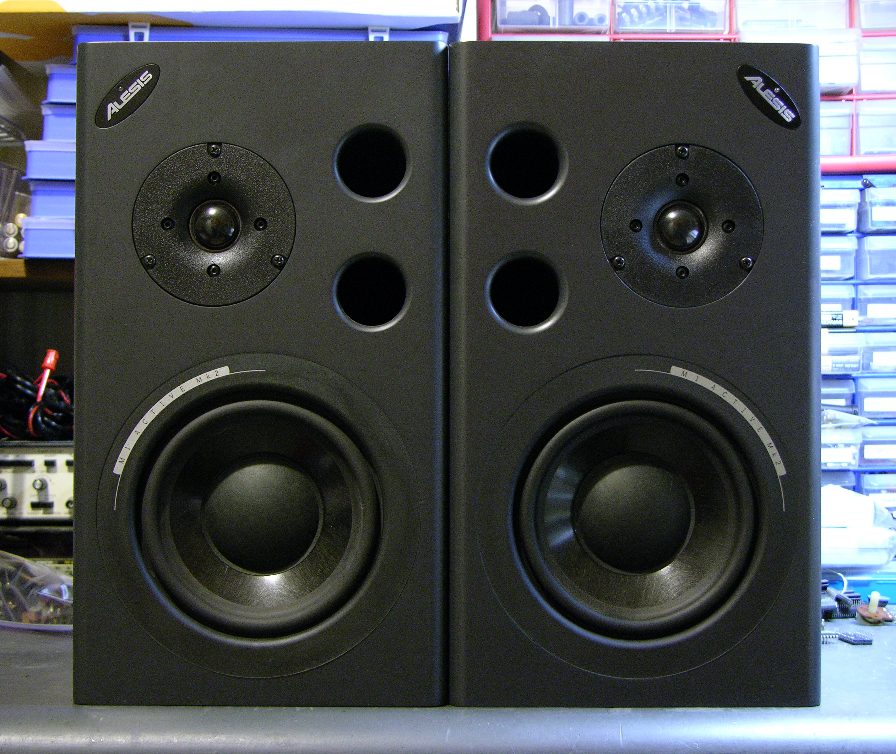
For Friday’s show, we used Alesis monitor speakers that we had in the lab, plus Steve, one of the students, supplied two.
During installation, one of the speakers started winking its blue power light and ceased playing sound, and before the show another did as well. Steve found a Studio Central forum post suggesting that the problem was due to a failed electrolytic capacitor that gets baked by a hot resistor right next to it, and a quick peek inside confirmed that it was a likely explanation and fix.
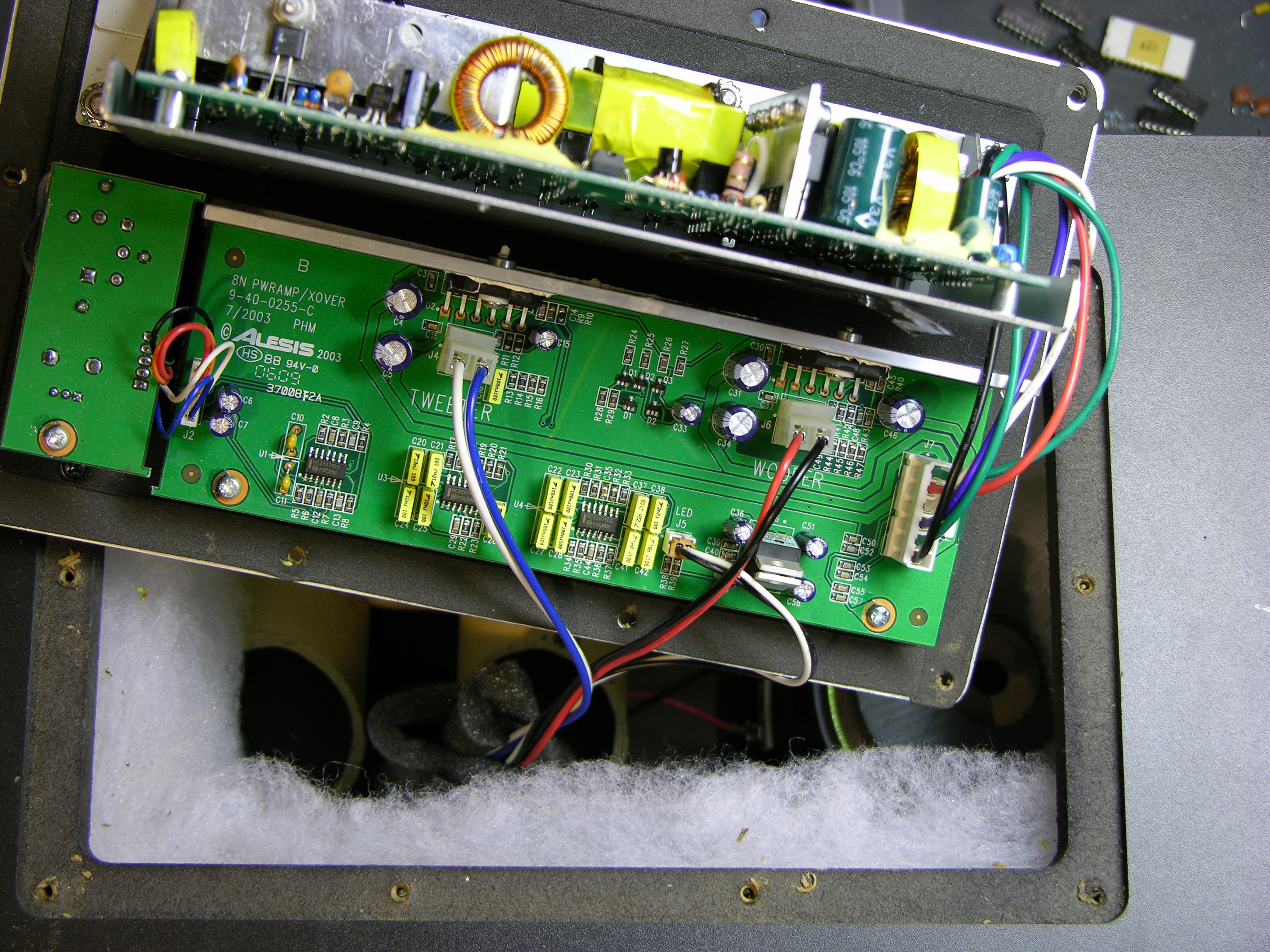
After unscrewing, the back panel lifts out and reveals the power supply board mounted vertically on a metal shield, and the crossover/amplifier board mounted flat on the panel.
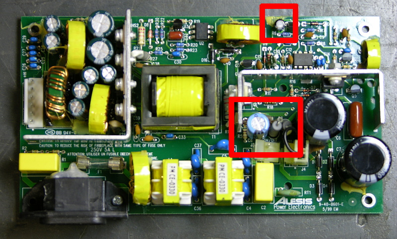
The naughty capacitor, C8 (actually its replacement after I finished), is in the center red rectangle next to the offending resistor. Another bad electrolytic capacitor whose number I forgot to catch is featured near the top of the board. Both of these tested bad with my Capacitor Wizard in-circuit equivalent series resistance (ESR) tester; all of the other electrolytics on the board tested good.
It was simple work to remove and replace the two capacitors on each board, and it brought both speakers back to life. Thank you, forum posts and Capacitor Wizard!
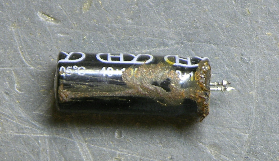
BTW, are electrolytics supposed to look like this?
Two caveats about this repair. First, I should have used 105°C capacitors, but I could only find 85°C caps on short notice, so these will fail quickly and need to be replaced again. At least now it’s known exactly what needs to be done. And second, the forum post suggests moving either the resistor or capacitor to get them further apart, which is a great idea but which I haven’t done yet. I’ve been trying to think up a clever way to stick a little heatsink on a vertically-mounted resistor, which might be a better solution yet.
I had the flickering blue LED and no sound on on of my M1 Active MK2′s so I pulled the board from the back and put the board in from my other M1 Active MK2 and it worked fine. When I pulled the “working” board out I noticed that C8 appears to have leaked over R4 and R5 but the board works fine. I put the bad board back in the speaker that was originally not working except for the quick flashing blue LED and it plays now but the sound pulses in and out. Any Ideas? Whats the value for R4 as it has gunk all over it and I cannot tell?
Keith, thanks for all you help!
I just finished replacing the C8 capacitors in both my speakers and everything works fine. There was no visible damage to them. I did not
replace the other capacitor like you did.
Now I finally have my speakers back and saved $200 in repairs! Thanks again!
Mahesh Mudigonda
In my case there was a shortcut in the poweramp. The powersupply could’nt give enough power and thats why the speaker acted as if the powersupply was broken.
I got the flickering LED on one of my monitors last week. Changed the capacitor yesterday and now it works like a charm! No visible damage on the old capacitor.
hi keith,
thanks for this info – am going to try to replace c8 this week.
on a side note, i think i see that you’ve got a jumper on j4, but the lower right corner of the red box around c8 is somewhat covering it. can you please confirm that 1) there is a jumper there and 2) you are in the united states?
i ask because i’m in the UK but may move to the US at some point and was hoping i could bring my monitors with me but there’s no voltage switch on them. i was told by alesis that a jumper was needed on j4 to change the voltage to 110.
thanks for your help!
chul
My Power Sockets are covered in hot glue to the extreme. How did you guys remove the Hot glue?
Hi there,
Useful thread…I also have the same problem as Mahesh above…I have a totally dead speaker – no light, no sound. Any info or pointers would be good, because it is clearly different from the flashing light thing.
It popped/crackled when I switched it on this morning (
(
For what it’s worth, my speakers are also situated in a cold place therefore perhaps heat (or lack of) is an issue with these.
Any help appreciated…thanks…
Matthew, my recollection is that I had the glue fairly cold so it was brittle instead of sticky and pulled/broke it off using a serrated-jawed needlenose pliers.
Unfortunately it’s pretty good glue.
I took mine to the music store I received them from as part of a barter to design their website in 2004 (Also got a KORG Triton XL 61) as I am not that great at soldering. The tech called me and said it would be $75 in labor for each speaker (2x$75) plus $8 each for the Capacitors. I asked him why it was so high and he said because of the hot glue that needed to be removed. I asked how much it would be if I took the power boards off and just brought the boards in unmounted. He said $10 a board in labor. I think it is worth $130 of my money to remove the glue myself.
Its about time for them to do some website updates too
Matthew, I laughed out loud when I read $65 per board to remove the glue. Yeah, you can handle it.
Keith, I thought it was pretty high myself for the task.
He did tell me that the resistor that causes the problem is not up to the task it was intended for and a larger resistor would probably keep the problem from happening again but there was not enough room to put the proper sized resistor in the original location (R4 I believe).
I really love these speakers. I was a full time pro club DJ from 1988-2000 and suffered some hearing loss due to various clubs using cheap monitors and dirty amps in the DJ booth. The Alesis sound great to me and I can run them flat in my studio with high end sound cards (Asus XONAR STX) so I definitely want them working. I would love to get a second set but it’s not in the budget right now.
I love your site and am going to try some of your recipes to learn electronics better. I am a Computer/Network/Storage Engineer and technical writer specializing in Virtualization. Thanks for monitoring (no pun intended) this Article/Post and replying so promptly.
If you ever need any Web Development let me know I would be glad to contribute.
Great Blog. Fixed my speaker myself. Payed approx 3$ for the capacitor.
Keith,
It took me about 20 minutes to get the glue off and the boards removed.
Matthew, you should evidently be billing at $390/hr!
That would be OK with me Keith!
Can you point me to where to get the right C8 caps at the correct value (A link would be great). After looking at the back of the PCB’s, I think I can tackle it myself. They wanted $8 per cap. I can save another $30 or so bucks and a couple of trips across town.
One thing that was weird. When I pulled the board from one of the cabinets there were about 6 thin long silver machine screws stuck (magnetized) to the Woofer magnet
I had posted earlier about my speaker being completely dead. I pulled out the C8 capacitor which I had replaced a year or two back. When measured it was near some 100 nF or so. (Probably some error from the meter).
I replaced this capacitor with a new one and it works great now.
So the same fix of replacing C8 works for the ‘blinking LED’ and also the ‘completely dead’ problem.
Thank you so much for posting this info. One of my beloved M1 Actives suddenly stopped working, and unlike most who have posted, my blue light simply stayed on as if nothing was wrong. I changed out capacitor C8 and now everything works fine! $1.50 at radioshack and a small soldering job. I also left the leads longer so it would be further away from the resistor.
Hunted down the caps at a local electronics repair shop. Took about 20 min. for the first speaker. The second only took 15 min. Thanks go to Keith and the rest of you.
Thanks for the info. Saved me getting a new power board. Had blinking light then got no pwr at all. Replaced C8 with 220uf 105 35v (25p from maplins pfff!) Works perfect. got the other caps aswell just incase but not needed em so far.
JP
Does anyone have or know where to get the schematic for the power supply? I have one that I did this repair to, and it didn’t work. I need to look at the schematic so I can find out what actually went bad. I’m trying to save a friend the cost of a new PS for this thing.
Thanks in advance.
Keith,
Thanks a lot for the info. I accidentally unplugged my firewire while my audio interface (M-Audio 410) was powered up. Both monitors were damaged and have the classic blinking blue light. I replaced the C8 capacitor (radio shack only had one) on the worst one and now I have sound again. I’ll fix the other one tomorrow.
I ordered a bunch of C8 Caps in case this happens again.
Thanks again, you saved me a bundle.
Mike F., glad this helped!
Be aware that I’m sure the capacitors from Radio Shack are only good for 85°C and will dry out pretty fast inside here. When you have a chance, get some rated at 105°C and you’ll get a little longer life out of them.
Has anyone had a problem with the resistor R27. I sent this speaker back and they replaced the C8 with a 105c and it appears fine but the r27 looks burnt now and maybe c38 also. Wondering if there could be an underlying problem that caused this to burn out. Should i just stick a new one in and see what happens?
Thanks. G
Hi again all,
Ok, so my speaker was completely dead, with no light and no sound. I have replaced C8 as advised but this has not fixed the problem. Still dead.
The internal fuse also blew…so I have also replaced this. I have switched on after replacing C8 and the fuse has not reblown.
The resistor R4 beside C8 is covered in gunk from C8 leaking. Therefore, I was intending on replacing this, but following the advice in the StudioForum post – link above in main text, that stated the resistor to be “resistor R4 (47K, 2 W)”.
I have purchased one of these, and what I have been sent is nothing like what is on the board (the one on the board is much smaller in size). Therefore I am assuming that either the rating of the resistor is incorrect, or maybe i have not bought the correct ‘type’ of resistor. Any ideas anyone? I am wondering if that should be 0.2w instead of 2w
Hmmm…any help appreciated…
Thanks for all the good advice in the thread anyway )
)
Tim, is your new resistor a big rectangular chunk of beige sand-and-cement? If so, you got a more readily available power resistor that’s probably coil-wound internally and is going to have inductance you don’t want in addition to not fitting the board. You probably need to spend a little extra on a non-inductive, carbon resistor.
As to the size and rating, I don’t have a schematic and I don’t have a speaker open, so I can’t check. But if R4 is the vertically-mounted resistor that’s cooking C8, yeah, it really is a 2W jobbie. Based on general knowledge of switching power supply circuits, I’d say it’s the bootstrap resistor that’s going to have maybe 200VDC across it all the time. It gets warm. It’s big. It’s 2W or more.
I don’t know where to tell you to find one in the UK. In the US, I go to Digi-Key, search resistors, and pick “non-inductive” from one of the filter choices.
But taking a step back, that’s a really hardy resistor and I have my doubts that it’s faulty. Can you desolder it and measure it out of circuit? My guess is it’s something else in the power supply that’s bad.
Keith,
I did order the 105C Caps from Centerpoint electronics. They were very helpful and I think I have a good replacement, see the part numbers below. I included the URL in case someone else is looking for them.
Thanks again….
10 EEU-FC1V331L EEU-FC1V331L $0.55 $5.50
10 NEV1.0M50AA NEV1.0M50AA $0.17 $1.70
Store URL: http://www.cpcares.com/index.html
Great! I had exactly the same problem. One speaker completely died a couple of days ago and the other one has been funny for a wile.
Change the C8 on both of them with a slightly more powerful cap (50v) instead so the will last longer. Only 1 euro for both of them.
No both work perfect. Thank u very much for the advice!
/C
Thanks Keith,
Great post, thanks for taking the time…….
I’m an ex power supply test/repair tech… eh 8 years ago!
I bought a pair of used M1 620 mark 1′s yesterday (1 with this fault). on the MK 1 model the PSU circuit board is mounted slightly differently but the same circuit.
Try the following…. Remove and replace C8 but instead of installing it in the same place beside the resistor SOLDER IT TO THE BACK OF THE BOARD and in through the same holes!!!!! the circuit board will shield it from all the heat and it should never fail again.
IMPORTANT!!
push the legs through to the front, leave 2mm slack, bend the slack over the edges to keep it in place. Make sure that you don’t reverse the cap by accident. remember -+
You can bend the cap back, flat against the board after soldering!!
put some non conductive shielding paper on (we used to call it “nomex”) between the body of the cap and the other solder joints for safety….
HAPPY DAYS!!!!:) should never fail again. if there is gunk on any comonents clean it off!!!!! you can pick up a flux cleaner pen (like a magic marker) at radio shack etc… or if in UK/IRE get it in Maplin.
I’ll be doing this job in the morning…. let ye know how I get on with it.
Lads, a higher voltage cap won’t make it last longer. tis the temp rating that kills it. If you still have problems after replacing that cap… simply look at all caps located near any FATTY resistors. Look at the top of ‘em. often they blow at the “X” marked on top of them.
You may see a bulge… if thats the case they are BAD.
The only way to test for sure is to desolder one of the legs and meter it.
If ye have old radios or any appliances lying around waiting to be dumped..
Open ‘em up… these are really really common value caps.
Have Fun!!!
Oh, Forgot to mention… Don’t trust you’re multi-meter when trying to measure the value of a capacitor, especially an electrolytic type!
Remember that a capacitor is like a battery and often stores charge when you’re circuit is switched off!!! often for hrs.
A multi meter usually can’t supply enough juice to charge the cap!!! it’s little 9V or AA batteries can only push a few mili amps and will give weird values!!!!
I would never increase/Decrease the voltage rating of a cap unless I was the design Engineer!!! They should blow if the voltage or temperature is wrong! if there is some other problem with the circuit and you’ve upped the caps voltage rating then you risk blowing other components in future. and you don’t wan’t to have a transformer being shorted. bye bye to the whole board as the PCB tracks and pads may fry!
If you must change the voltage rating, no more than +/- 10%. A design engineer usually works with that amount of tollerance:)
I’ll just pick up a mixed bag of caps in Maplin for 10 euro’s and find the correct value.
Tim B…..
If youused the wrong type of cap but with the correct ohm rating… You would probably just pick up some hiss noise when the speaker is on!
If it worked initially and died suddenly, look for cracks on the body of the resistor! If none it is probably OK.
If you have a multi meter, test the little diodes near by. the black stripe is the negative side of the diode! set the meter to the highest resistance in MEGA ohms. stick the red lead to the negative side of the diode & the black to the positive. You are looking for a “leek” you should see infinite resistance if she is OK!
After that swap the leads around. black to black… red to positive set the meter to the diode setting. you should see 0.6V issshhh.
I’ll take a closer look at the board on mine tomorrow, if I’ve any ideas, i’ll let you know
BTW it is often very easy to make silly mistakes. double check that the new cap is not reversed!!!! it’s easy to do!!! i’ve done it b4:) that would give you no power!
I’m very glad to have found this forum/blog. Thank you for being here. All of you.
I had the infamous blinking light in one monitor occasionally for quite a while, did nothing about it because powering off/on did the trick and I didn’t think I could fix it on my own and couldn’t afford to send it out and lose incoming work. Last week the flashing light became permanent.
I read a forum, opened up the back, found C8, saw leakage from it, replaced it with a 220uF, 50v 105º cap… plus I replaced both R4 and R3 resistors (2W-47K). That done, I closed up, plugged it in, hit the power and a big fat nothing (insert deflating sound here). No power.
I’m not a great solderer, but it couldn’t be that, since I was just replacing those particular resistors and cap, could it?
Incidentally, the new cap is fatter than the original 330uF 35V 85º cap, which worried me a bit when replacing it. But I read that a 220uF, 50V, 105º was a fie choice. Being fatter, I tried to make sure I wasn’t touching anything around it. Also, the two resistors I ordered and replaced are shorter and blue, as opposed to the original gray ones. Is that irrelevant as long as they are 2W-47K?
Sigh… I opened it back up and looked closely at all adjacent components and saw what could be some minor leakage from C6, the big black one a couple of spots away. First I thought it was from C8 leakage but now I’m not so sure. Is that C6 cap known to blow?
Can leakage from one component damage adjacent components? I’m also worried about that little tiny D5 resistor next to the C8 cap.
So many questions and here I am new to the blog. Sorry.
Meanwhile, a client waits for me to start mixing his live recording. Argh.
Help?
Hi again,
Thanks for the comments Ronan – I will investigate what you suggest regarding testing with multimeter.
I thought it might be useful for me to add a bit more info for others with similar issues.
My speaker died, no power/light – I replaced C8 and the internal fuse which blew, and tried again. It still doesn’t work, but now blows the fuse in the actual plug of the kettle lead when I switch on – 100% every time (I blew several before I realised what was happening!) – not sure why this is – need to investigate further.
I should also add that my other speaker has now done exactly the same thing…switch on, crackle, no light/power any more.
So both have gone very similar times, and both show C8 leaking like mad all over R4. I am not sure if it is relevant, but the speakers have recently been moved to a much colder environment (close to freezing at night)
I replaced C8 with a 35v 105c as stated. However, I should note that my original C8 is actually a 165c version 330uf which has not been mentioned at all in the thread. I am in the UK btw.
Anyway, good luck all…
In response to Tim B and others. My original C8 cap was 330uF 35V 85º. So I guess they weren’t consistent over the years. I spoke with tech at Alesis and mentioned the fact that there were so many people online with the same problem and that many have pointed to it as a design flaw and all I got was “We’ve never heard of anyone with that problem. Beware of what you read on the internet.” I told the guy he should have anothewr job if he doesn’t know enough to poke around a bit and report back to the engineers on this. What a pisser. Anyway, now i’m waiting for a PCB power supply because i burned up my board a bit trying to do some very amateurish (apparently) soldering. Would still love a response to my above post regarding C6 and whether or not leakage from one can damage another. Thanks.
I had replied in October last year but have been putting off actually repairing but today I decided to give it a go. I am happy to say I have fixed the speaker, so thanks again for this blog post.
I replaced the C8 capacitor and it solved the problem
hya just wondered have looked at board and r27 and c38 are burnt same problem as greg mosley has anyone else had this and have they had to replace c8 and r27 and c38 thanks alot
I am repairing a set of the Alesis M1 Active 620s with the capacitor problem. The electrolyte has either covered the diode underneath it completely, or split it in two. Does anyone know the value of that diode? (It’s tiny and red.) Thanks!
I think it is D5 or D6 on the board.
It is D5, which is a BAV21. Hopefully, this message will post this time.
Hi there! (sorry my english)
I´ve got problem whith one of my speakers. Alesis MK2.
When I turn it on, I can hear a sound like “boff, boff, boff, boff, boff”.
The circuit board looks good, all capacitors m.m. (have no ESR)
Is there anybody who remember this problem.
and have any idea, what problem is?
Kenneth Rosén
hi to everyone i have a set with one not working but one which works fine if anyone is intreasted in them for spares im looking for £50 + postage uk only worth that as the woofers are great and power supply is good you can contact me scottball@sball.demon.co.uk
MikeB says:
January 7, 2010 at 03:56 pm
I found the faulty component, it was the power amp for the bassspeaker that was blow away. I would like to thank you Keith for showing interest and answering me before…..
Hallo (sorry my English)
I have same problem whit my Alesis MK2 (ticking sound)
Where can I find the “power amp for the bassspeaker” on the circuit board? (number)
Best regards
Kenneth
Same problem with my Alesis M1 Active Mk2 – left one started blinking intermittently, then the whole thing went dead later.
I just pulled out the power supply circuit board and looked at it. From the underside of the board, it is very clear that the thermal (heat) design of the board is faulty. There are two areas of the (bright green) circuit board that have actually turned brown from excessive heat – something that should never happen in a properly engineered circuit board.
One of these overheated areas is centered on the two power resistors R3 and R4 which are right next to C8, the capacitor that dries out from the heat according to this blog post. Given the evidence of excessive heat here, I agree that it is very likely C8 will be slowly cooked to death due to its location here.
The other overheated area is near the top left corner of the main transformer. The source of the heat is another power resistor, this time its resistor R27. In the 3rd photo in this article, the transformer is the square black thing with a bright yellow center near the center of the board. Look near its top left corner to find R27 – or just turn the board over and look for the areas where the normal bright green has been charred blackish-brown from the heat!
By the way, the power transformer on my board has a wrap of copper tape around it, covering most of that bright yellow area. The copper tape is an electrostatic shield, reducing electromagnetic noise radiated by the transformer (which can show up as audible hum, buzzes, whistles, and other noise in the speaker output).
Alesis Electronics went bankrupt and was bought by NuMark for pennies on the dollar in 2001. As far as I know, no former Alesis employees were hired by NuMark, so it’s no surprise Numark has never re-engineered the original decade-old flawed power supply board – they may not even have an engineer on the payroll with the skills to do so.
My Alesis M1 Active Mk2 monitors are several years old, so judging from the photos in this blog, it would seem that Numark, the new owners of Alesis, cheaped out and took away the copper electrostatic shield on the transformer to pinch a couple of pennies.
I worked at Alesis in the late 1990′s, and knew all the engineers behind the M1 Active Mk II. The superb sound of the M1 Active Mk II is the result of loudspeaker designer Patrick Hart’s work – he worked for years with the Taiwanese manufacturer of the woofer and tweeter to bring them up to very high quality, and he designed the enclosure, porting, and other loudspeaker aspects that you hear. The audio amp electronics were very competently designed by a couple of electronics engineers on the team. Pat Hart specified the crossover frequency, and when the original design by the audio engineers did not sound good enough for his critical ears, I identified the flaw in the design and provided the engineers with a time-alignment circuit and design equations. Adding the time-alignment circuit to the existing crossover network design resulted in the superbly seamless crossover design used in the final product. Pat was very happy, the speakers had fantastic imaging through the critical crossover frequencies, and I had the pleasure of knowing I helped make an already good product a little better yet.
The power supply, though, was designed by a different engineering group – their mission was to cut the cost, weight, and size of Alesis power supplies by designing switching power supplies to replace the traditional analog ones. The M1 Active Mk II contains one of the first switching power supplies designed by this team – and, as we all now know, they didn’t quite get it right. The power supply is sensitive to spikes in the AC voltage and slowly cooks itself to death.
-Obscuro
So, I’m completely unable to get the back off! LOL. All the screws on the back are out, but that panel will not budge! What am I missing, please? If it’s something COMPLETELY stupid, that’s okay…I can take it!
Obscuro writes:
I don’t disagree, BUT I’ll point out that I’ve never once met a switching power supply whose bootstrap resistor hadn’t scorched the PC board.
Some just put their filtering capacitors a little further away than others.
Pappy- thank u! These diodes are driving me crazy! Keith- thanx 4 the blog!
I couldn’t get thorough help any where else!
You’re welcome. I just wish I could get my hands on the schematic for the PS. Alesis sent me the schematics for the amp board twice, and I can’t seem to impress upon them the fact that the power supply isn’t in there.
I really don’t want to, but it looks like I’ll be doing some reverse engineering to get this thing fixed.
Kenneth Rosén
First of all you have to be sure the powersupply is working, I switched the powersupply from the working speaker to to non-working speaker and vice versa. If the speaker still ticks and the blue diod is flashing, the poweramp may be the faulty component.
You have two poweramps, one for the low and …tada… one for the high freqs. If the base speaker is pumping then you can assume that the low poweramp or something in the low poweramp chain is the fault.
The poweramps used in these speakers (Alesis M1 Active Mk2) is LM3886T or LM3886TF and can be found by searching the net.
Thanks MikeB
I´m going to try with, what you says. But, when you say “powersupply”. Do you mean the whole circuit board. As the stream connected to?
How much have you payed for the power amp?
Was it the low freq or hight freqs for you
Thanks again
Kenneth Rosén
Kenneth R
Inside the Alesis M1 Active Mk2 there are two circuitboards, one is the powersupply and the other is the poweramplifierboard. What I did to test which board was faulty was to completly remove the powersupplyboard (the one with most components on) and switch it with the working speaker. If I don’t remember wrong there was on contact from the on/off switch going to the powersupplyboard and then the cable from powersupply to powerampboard. Right next to the contact from on/off there is a similair jack, be shure to have it right, it is for switching 110v / 220v. In my case I have 220 v and there was no jumper on that connector.
When you have established the probably cause to be the poweramp you have to either test which one it is (I did so by desoldering one from the working powerampboard and placing it in the non working, but that takes time and you need to have the basic skills in soldering/desoldering and of course the right equipment) or just jump to the conclusion that it probably is the poweramp who is responsible for the problem.
In my case it was the low freq poweramp (closest to the connector to the powersupply), but as I did’nt measure anything I suppose the same fault may appear when the high freq amp is blown.
I payed about 100Skr (10euro, 15$).