For Friday’s show, we used Alesis monitor speakers that we had in the lab, plus Steve, one of the students, supplied two.
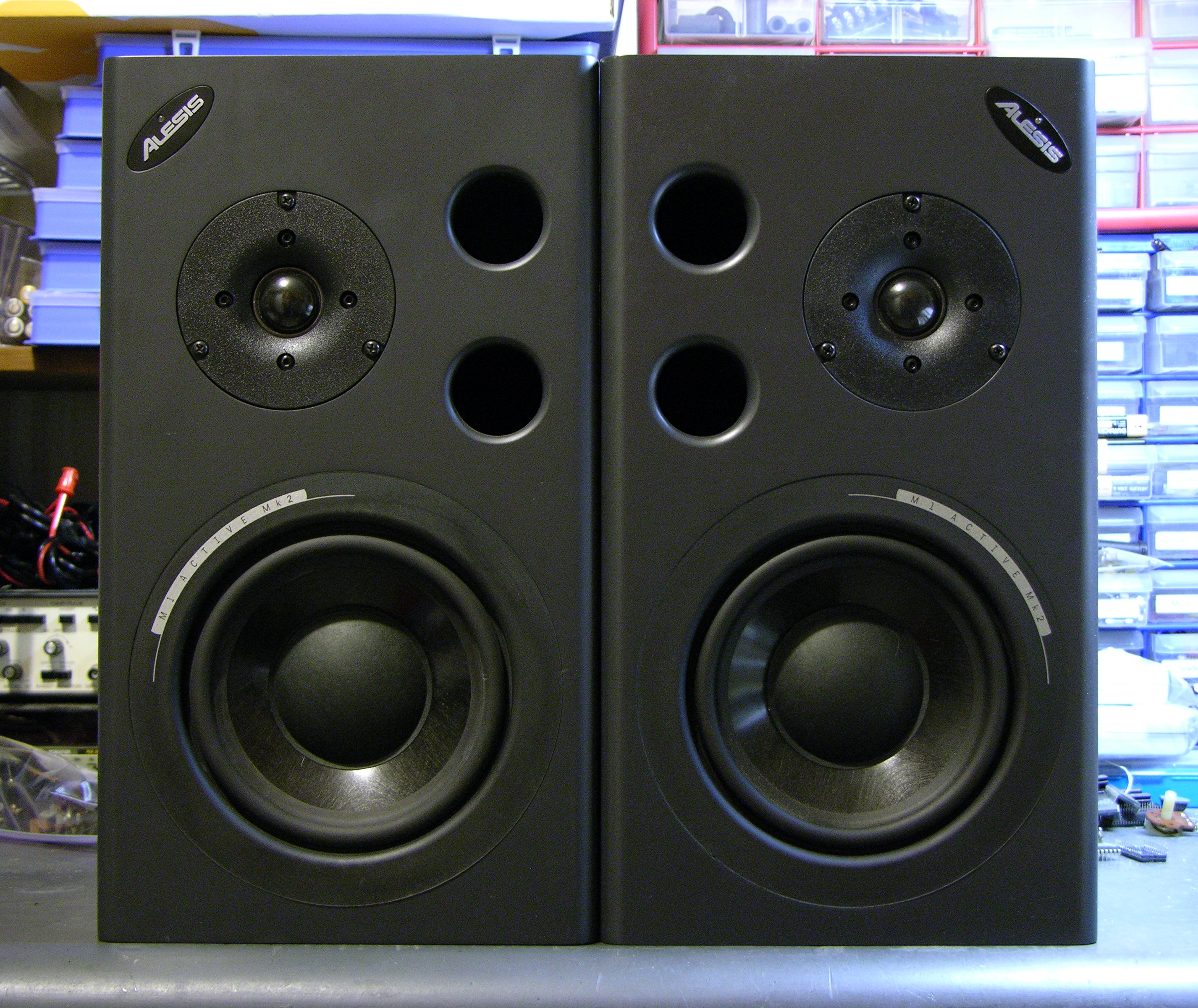
During installation, one of the speakers started winking its blue power light and ceased playing sound, and before the show another did as well. Steve found a Studio Central forum post suggesting that the problem was due to a failed electrolytic capacitor that gets baked by a hot resistor right next to it, and a quick peek inside confirmed that it was a likely explanation and fix.
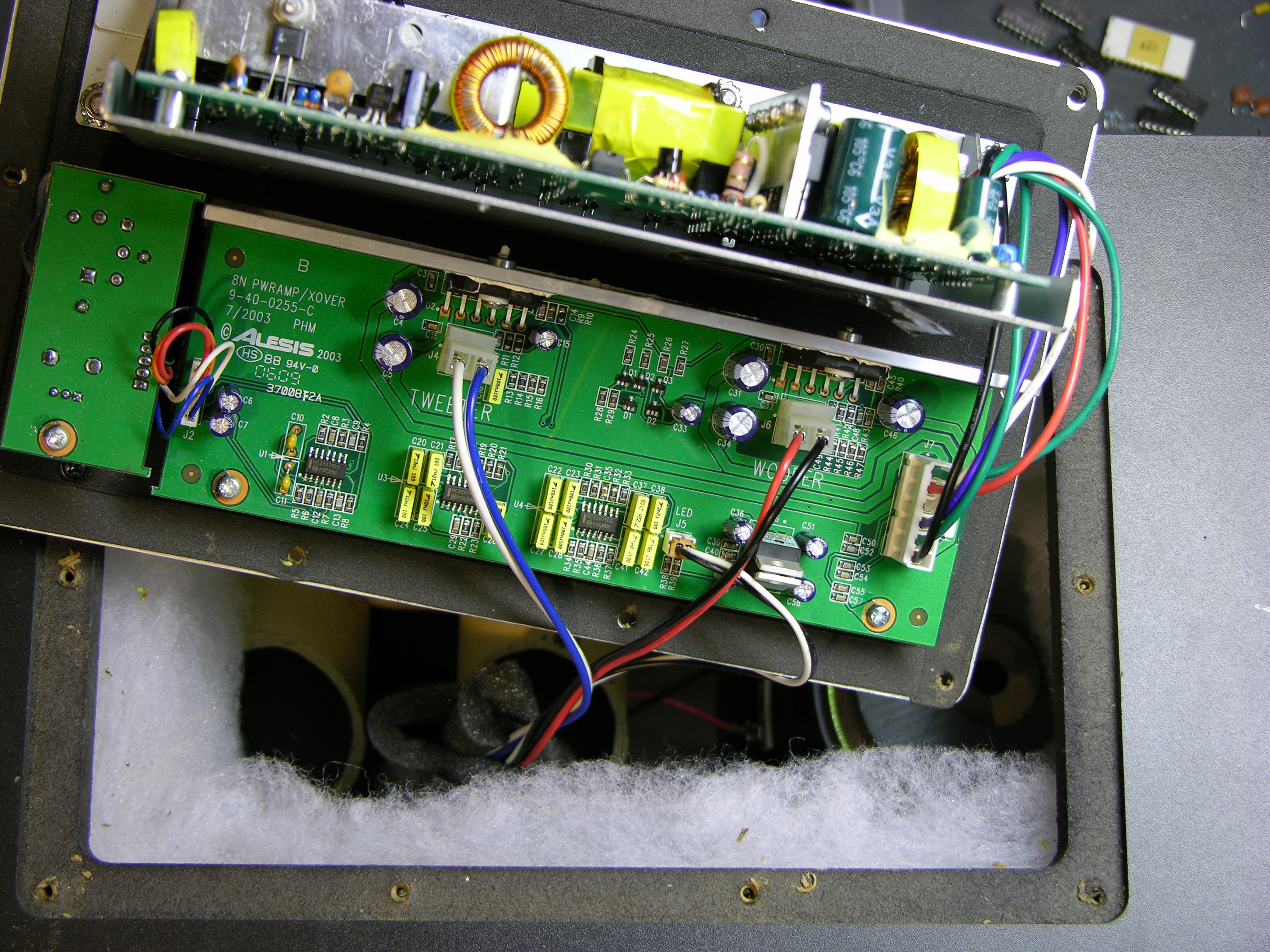
After unscrewing, the back panel lifts out and reveals the power supply board mounted vertically on a metal shield, and the crossover/amplifier board mounted flat on the panel.
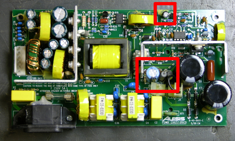
The naughty capacitor, C8 (actually its replacement after I finished), is in the center red rectangle next to the offending resistor. Another bad electrolytic capacitor whose number I forgot to catch is featured near the top of the board. Both of these tested bad with my Capacitor Wizard in-circuit equivalent series resistance (ESR) tester; all of the other electrolytics on the board tested good.
It was simple work to remove and replace the two capacitors on each board, and it brought both speakers back to life. Thank you, forum posts and Capacitor Wizard!
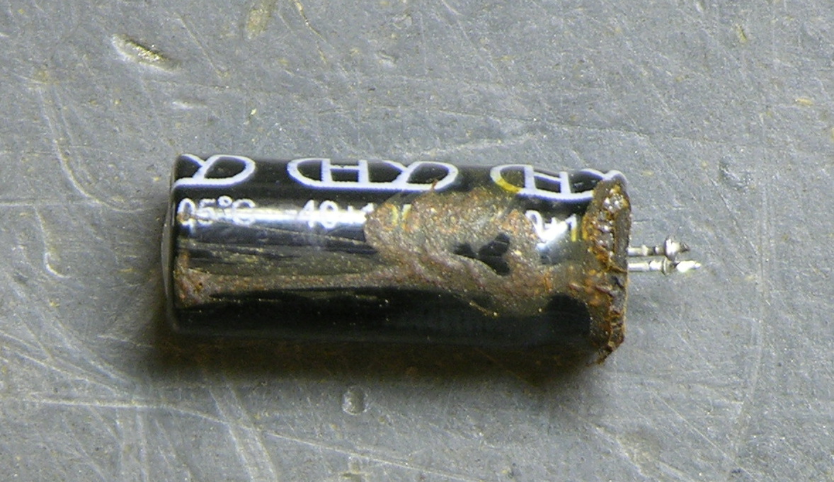
BTW, are electrolytics supposed to look like this?
Two caveats about this repair. First, I should have used 105°C capacitors, but I could only find 85°C caps on short notice, so these will fail quickly and need to be replaced again. At least now it’s known exactly what needs to be done. And second, the forum post suggests moving either the resistor or capacitor to get them further apart, which is a great idea but which I haven’t done yet. I’ve been trying to think up a clever way to stick a little heatsink on a vertically-mounted resistor, which might be a better solution yet.
Can someone advise for C33 please?
I figure its 0.1 UF.
Would this be ok?
http://www.maplin.co.uk/resin-dipped-ceramic-capacitors-297
Check the caps on the output side of the flyback. They are probably just as worn out as C8. They may not be leaking fluid, but they don’t seem to be killing the “hum” left over from the flyback. To see if that’s it, I’d replace every electrolytic cap in the afflicted speakers, starting with the output side of the power supply. I’d also be sure to check the caps on the amp board to be sure the decoupler caps are working properly.
Considering the cost of electrolytic caps, completely recapping the speakers wouldn’t be cost preventative, as the entire collection of caps in the unit is at most, worth about five dollars. This will most likely cure the ill.
Cheers,
Pappy
Hello to you all!
I have a blinking light as well. The difference is that it only blinks after having the monitor on for more than 1/2 hour or so. This has been going on for about a year now. I have opened it up and taken a close look around and cannot find any damage at all. There is a sloppy bunch of yellow-ish goo all over, but that is all that looks weird to me. Then again, I have very little idea of what I am looking at..
Thanks!
Yes, C33 is 0.1 uF, 50V.
Cheers,
Pappy
I agree with the other dude. RT1 is very hard to find.
Mouser wanted 12 GBP to post a component the size of a childs toe nail!!!
If the sloppy goo is rubbery, it belongs there. Look again at the photo of the PC board from top down. The caps in the center of the red boxes are the caps involved. Remove and replace them, and that should stop the blinking.
If you don’t know how to solder, or whatnot, you might want to let a professional do it. Something like this isn’t really the best project to start with if you’ve never wielded a soldering iron.
Cheers,
Pappy
They could just stuff it in an envelope and send it airmail. I’d think that would be cheaper. I’d be on the lookout for Alesis in Europe if I were you.
Cheers,
Pappy
Hi, we fixed one of my m1 active mk2′s following some earlier advice from another site I found but then when I came to fix my other speaker (as both were blinking), we replaced the offending capacitor and resistor but then got no power or blinking lights ;( haven’t replaced the one at the top (in the red square) but I’ll try it… does anyone know of any other parts that can get blown by this problem? What were Alesis thinking? Cheers the photo’s really help
to Maffi- I would check to see if you have the polarity right on the capacitor. + on the cap lead must go to + on the board. Also, recheck your soldering job (somehow you lost a connection in the supply path for it to go ‘dead”) and replace the other cap since you are in the box anyhow.
Thats it for me, I’ve given up. The amount of time and effort I have put in to replace about 6 compnents is just not worth the time.
Anyone want to buy a spare?
I’m in London.
chris.maskell@live.com
So I have the flashing blue light of death on one of mine too, and found this place searchng the fix… I called radio shack and they have the capacitor C8 (220uF, 35V) for $1.49 each. So any of you who need to get the same fix, go to radio shack, they have them MUCH cheaper than the $8 i keep seeing people say it costs…
zbizzy, when I checked Radio Shack, they did not have the capacitor rated for 105°C, only for the more common 85°C. The one in the monitor that dried up and broke is already the high-temp version, and replacing it with an 85°C capacitor will result in replacing it again soon.
If Radio Shack now carries 105°C caps, please post a part number here and we’ll all save some effort!
zbizzy,
If you live in or near a big city, or even a smaller one, there should be an electronics outlet of some type other than Radio Shaft. You will get better pricing, and you can get the proper part that will fix the issue more or less permanently. Look it up on the web or in a phone book.
But like was said above, if you find a deal on the proper caps from the Shaft, don’t keep it to yourself.
Cheers,
Pappy
Pappy,
It has been a while since my last post. The board is dead and I do not have the time (nor patience) to get it working (I did replace a lot of components). My father-in-law was killed in a car accident by someone driving on a suspended license and this has been a rough couple of months to say the least. I did promise to send you this board if I was unable to repair it and I would still like to follow through. I just do not want to post my contact info on this site. How would you like to handle it? I live in St. Pete, Fl. I figured you helped me through getting all of the parts (and replacement strategies) so it is yours. I ordered extra replacement parts that will be sent as well. Thanks again Pappy and I look forward to your response.
-Tal
Tal and Pappy –
I have both of your email addresses via my blog server and would be happy to exchange them for you if you both find that agreeable.
… no problem on this end and thanks a bunch Keith!
Cool. Go ahead and make the swap. Thanks
Cheers,
Pappy
Tal,
My condolences on your loss. We just had a recent death in our home, so I can relate to where you’re coming from.
Cheers,
Pappy
One of my monitors have the blinking light is it hard to change myself and can I get the part at walmart or target
If you know how to solder, yes, you can do it.
No, you will not be able to get the part at target or wal-mart. If there’s a Fry’s electronics in your area, you will find it there. You might also find it at a Radio Shack, but it would be much better for you to consult your local yellow pages. Look under “electronic parts” in your local yellow pages.
I’ve been using Parts Express for a while now at partsexpress.com for my electronic parts needs when my local parts store doesn’t have what I need or I’m not up to doing the 16 mile round trip. Radio Shack also has a limited selection of parts at stores. I’m glad I found this blog as I was looking at a pair of M1′s for sale locally.
Just make sure you buy 105°C rated capacitors, which I don’t think I’ve seen at Radio Shack. Standard 85°C will dry out faster than you can say, “I wish I’d bought better caps.”
Hi
Came across your posts trying to figure the value of RT1 half of which has long dissapeared into orbit. sadly it was the bit with the code written on it.
wondering if any of you chaps wodl mind posting a pic or the code on the PTC Thanks
RT1 = Thermistor, 10 Ohm 2A NTC
Cheers,
Pappy
Is this a good C8 candidate ??
Samwha Electrolytic Capacitor 330uf 35v 130′C C84 ?
Or is this more correct?
20pcs Panasonic FC Electrolytic Capacitors 220uF/35V
Will it matter that it is rated 330uf and mine is rated 220uf ? I don’t want to blow anything.
Thanks,
hi everybody, someone knows the D5′s reference, I can’t see it ’cause the diode is broken, I know it must be a zener diode (less than 30V) but I wanna know the exactly reference. other side, what is the value of R3 and R4, the resistors are burnt, I measure them but the value must be wrong (38K).
thanks
D5 = DIODE: BAV21 SOD-27
Cheers,
Pappy
“Will it matter that it is rated 330uf and mine is rated 220uf ? I don’t want to blow anything.”
While I always prefer to go with the part that the engineers used, I don’t see your choice making anything go boom as long as you don’t put the caps in backwards.
Cheers,
Pappy
i measure r3 and r4 and have same value (38k). is this ok??
my q3 and q4 are 2n5551 and 2n5401!
can you please send me a schematic for Monitor M1 620?
draguljche83@gmail.com
thank you very much, and sorry for my “Tarzan” english!
Here are the part numbers for the capacitors:
MCM Electronics
http://www.mcmelectronics.com/
31-5685 Capacitor 35v 220UF Low ESR 105C (This is C8)
31-7285 Capacitor 50v 1UF 105C (This is C35)
I installed these and my M1 is working. Thanks for the posts!
anyone knows something about C6, please?
Hi there, my speaker is dead, upon opening it it looks like the fuse, i am just unsure what amperage or whatever to replace it with. as for the overheating of the capacitor, any ideas of how i can prevent this? Any assistance will be much appreciated.
Nice one
Can somebody identify the two yellow boxes on the power supply board, one one the left side next to the power connector and the other below the capacitator. references C1 and C2.
Thanks
sale,
R3-4: 47K OHM 2W 5%
Q3=2N4401
Q4=2N4403
none,
C6=390uF 200V
chironex,
C1, C2=0.22uF 250VAC 20%
Cheers,
Pappy
PS, if anyone does have the schematic, I’d like a copy as well.
Can someone please let me know the R11 value (ohms) ?
Thankyou Pappy,
Can i use also a high frequency Cap for C8 or it must be a low esr?
I’d use what’s called for, as that’s usually the best thing to do.
Cheers,
Pappy
both tweeters have stopped working on my pair. Any ideas anyone? they basically sound like their playing from under a duvet!
Help!!
thanks
rohan
Hi thank you for the information here.
I’m about to order my components, I found a website where they don’t charge too much for shipping(I’m in France). The only problem is that I can’t find a 2W 47K resistor, they only have 1 or 3W.
Is this a problem?
Either the tweeters or the amps that run them have gone bad. Best way to find out the real issue is to pull out each of the tweeters, and attach the leads to a spare loudspeaker. DO NOT SHORT THE LEADS!
If you hear sound, then the tweeters are bad. If not, then it’s likely both the tweeters AND the amps are dead.
Tweeter drivers P/N:7-02-0018 (Alesis only)
Amp P/N: IC LM2876 POWER-AMP 40W 11-PIN TO-220 (Local electronic parts shop (read NOT Radio Shack) or on-line (Mouser.com))
Cheers,
Pappy
Mike,
R11=1K OHM 1/8W 5%
I missed your message earlier. My apologies.
Cheers,
Pappy
Dear friends, what I’m gathering is a myriad of suggestions. What I’ve already done, (which I’ll undo) is replace the hemorrhaged caps with 85deg 330uF 50V’s, so I’ll seek out 105 or 130deg caps. But I really need to confirm, as I’ve removed the r4, is that they are truly 47k 2W resistors. As they needed to be replaced, i’m just concearned because mine looked like thermistor 50k’s and I can’t afford to blow anything. Mine were glass resistors, can anyone confirm that’s what they looked like?
On a side note, I had an acquaintance suggest using a resistor pot, but I don’t see any viable way to disperse heat any more efficiently then with a thermistor resistor, thoughts?
Thank you for any and all assistance.
@ Edised- You would have to go with the 3W but the physical size may be a problem. The leads may be too big to fit through the holes in the circuit board. The work-around would be to use the leads from the original resistor on the board and solder the new leads to them. It can be tricky as heating the “splice”
joint tends to heat the connection to the board too. Use a heat-sink clip to isolate the circuit board joint from the splice joint.
“The only problem is that I can’t find a 2W 47K resistor, they only have 1 or 3W. Is this a problem?”
In general, I never recommend someone re-engineering something unless they know what the consequences might be. That said, if you must deviate from the original part wattage wise, it would be better to go for the three watt resistor, as the one watt might be able to dissipate its heat properly. That could create a fire hazard. The three watt resistor would run cooler, and be less likely to burn.
Cheers,
Pappy
Onefreewalk,
R4=47K OHM 2W 5%
As far as using a pot, there’s really no reason to, and you’d need a high-power dissipation style pot… Those aren’t cheap. Use the right parts, you can’t go wrong.
Cheers,
Pappy
Power handling was exactly the issue I was concerned with. I have no problem installing a 3W, in fact I’m going to order all the parts online tonight, I just wanted a confirmation first. Thank you guys very much, your help is permanently appreciated, no matter the outcome.
Well, as of today the two caps and resistor changed in the article are all replaced, but to my dismay I’ve still got the blinking light and matching tweeter click. So now I think I just need a way to test the rest of the components ( obviously). I bought the components from Digikey and was impressed with their price, selection and shipping.
My question is a recommendation for a tester that will correctly tell me the condition of the remaining testable components. I look forward to more helpful advice.
Onefreewalk
Onfreewalk,
My first thought would be to double-check that you’ve got everything installed correctly. Electrolytic caps are a one-way thing. If the caps you’ve replaced are properly polarized, check to make sure the PC board doesn’t have a wad of capacitor juice that might be shorting things. If so, rubbing isopropyl alcohol and Q-Tips were tailor-made for cleaning that particular mess. Finally, check your solder joints to make sure you don’t have any bridges, excessive rosin, or cold joints. Resolder the cold joints, fix bridges, and use the alcohol/Q-tip trick to clear excess rosin.
Since I don’t know your level of proficiency with a soldering iron, let me suggest this URL: http://www.aaroncake.net/electronics/solder.htm . It has a great study in cold joints at the bottom of the page. His good joints are really good. I lay it on a bit thicker than he does, but life is like that sometimes.
If, at the end of that, you find that everything’s proper and true, inspect and replace the rest of the caps. There might be another bad one down the line somewhere. If I were working on it, that would be my next move. After that, it’s time to start checking for fried semiconductors, and so on until you find the bad part(s).
Cheers,
Pappy
Thanks Pappy for the quick responses!
I am very proficient with an iron, and the traces are clean and polarity’s good, no cold joints, I was hoping to test the other components before replacing all of them. So I’ll continue looking for a tester that’s affordable, what I have learned is that some multi-testers actually measure capacitance. Would the tester be trustworthy enought to not have to buy a Cap Wizard like keith mentioned, (I’m an audio engineer, and unfortunately not an electrical engineer). It’s really nice to have a person to ask these questions, I appreciate your help.
thanks
If you find a Fluke with capacitance testing, you can pretty much rely on that. There are some out there.
Good luck.
Cheers,
Pappy