For Friday’s show, we used Alesis monitor speakers that we had in the lab, plus Steve, one of the students, supplied two.
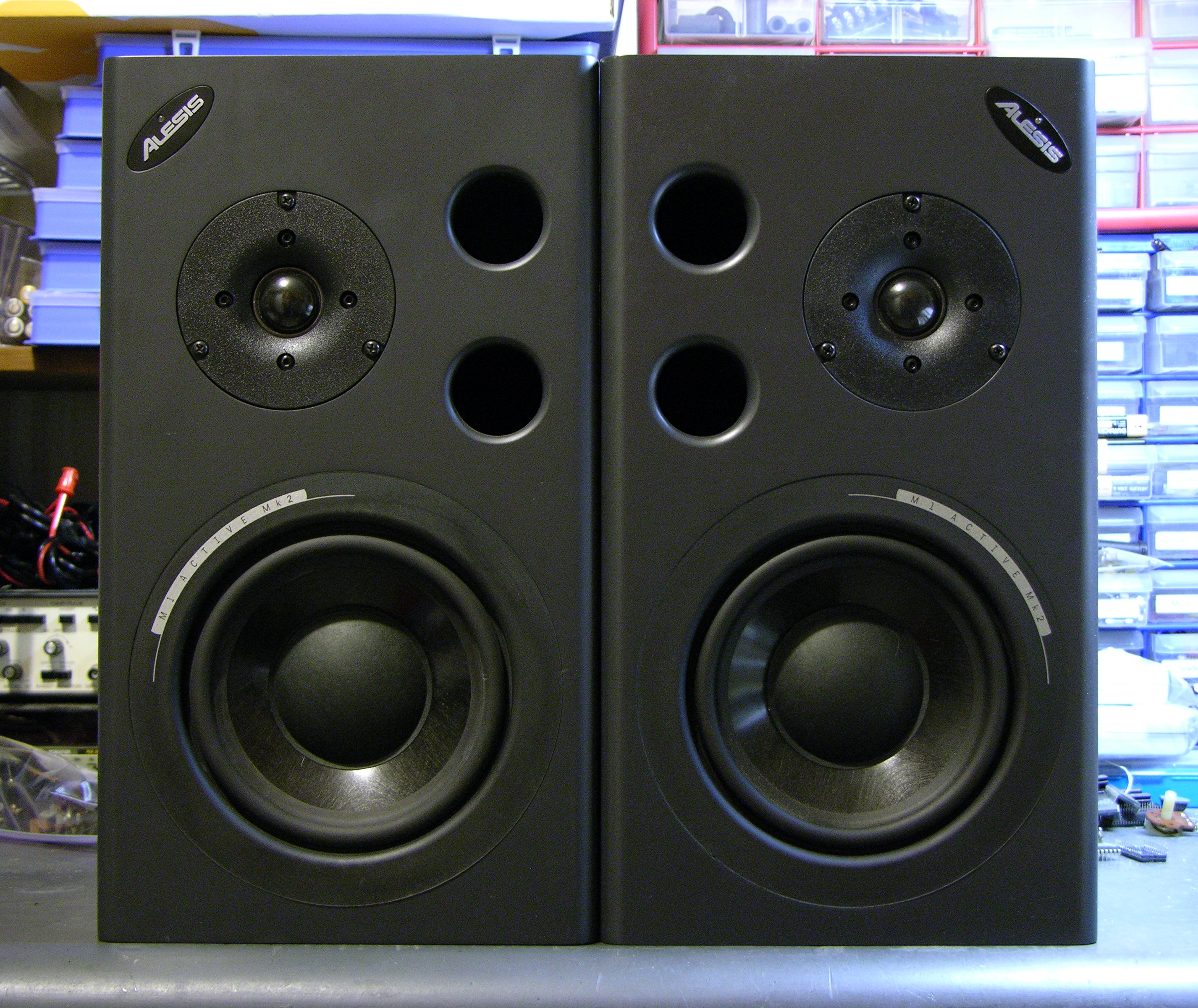
During installation, one of the speakers started winking its blue power light and ceased playing sound, and before the show another did as well. Steve found a Studio Central forum post suggesting that the problem was due to a failed electrolytic capacitor that gets baked by a hot resistor right next to it, and a quick peek inside confirmed that it was a likely explanation and fix.
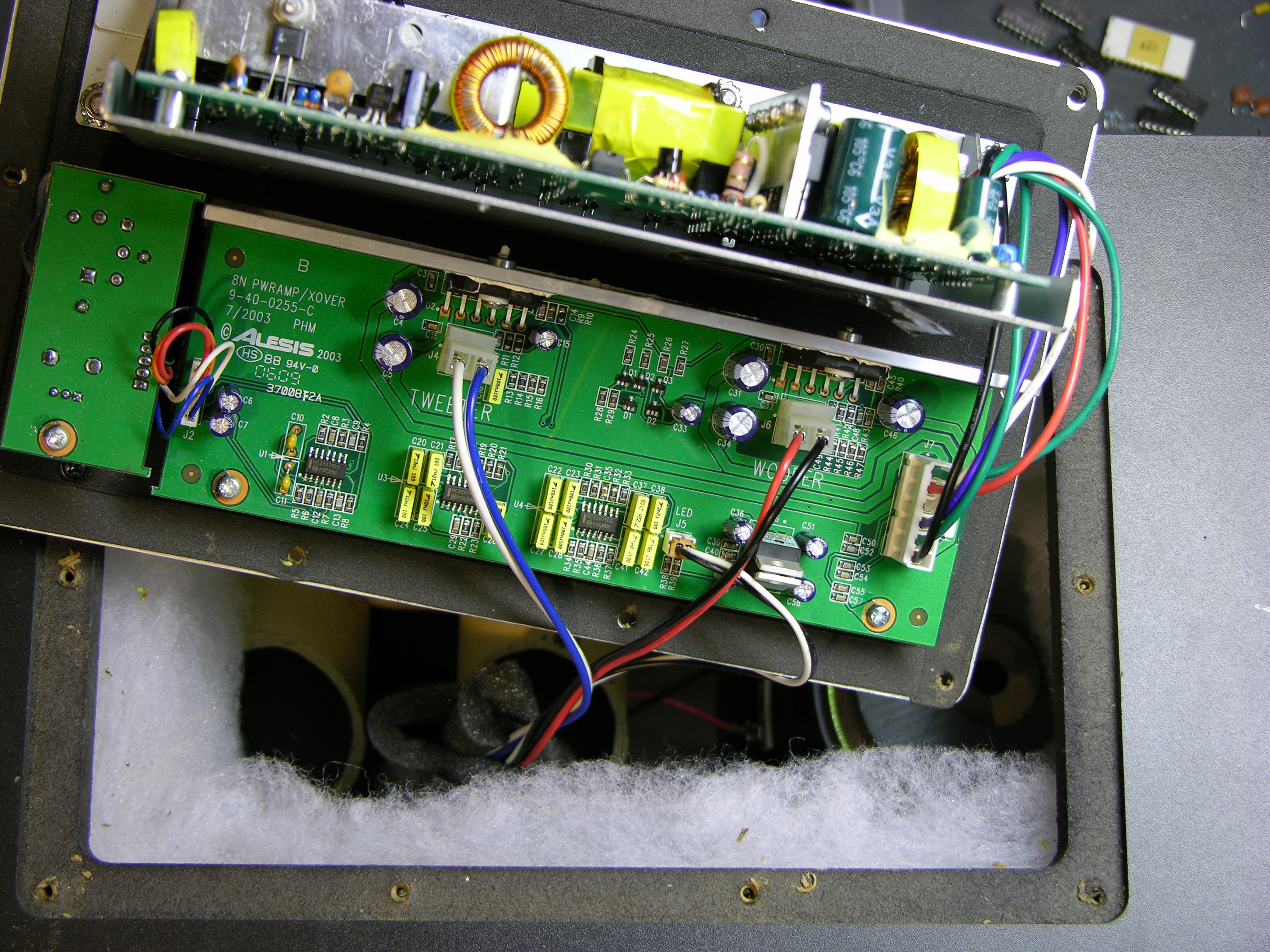
After unscrewing, the back panel lifts out and reveals the power supply board mounted vertically on a metal shield, and the crossover/amplifier board mounted flat on the panel.
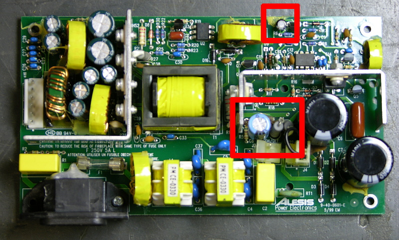
The naughty capacitor, C8 (actually its replacement after I finished), is in the center red rectangle next to the offending resistor. Another bad electrolytic capacitor whose number I forgot to catch is featured near the top of the board. Both of these tested bad with my Capacitor Wizard in-circuit equivalent series resistance (ESR) tester; all of the other electrolytics on the board tested good.
It was simple work to remove and replace the two capacitors on each board, and it brought both speakers back to life. Thank you, forum posts and Capacitor Wizard!
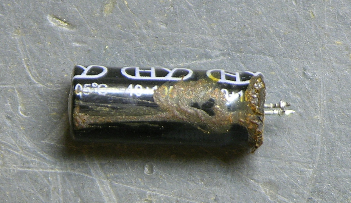
BTW, are electrolytics supposed to look like this?
Two caveats about this repair. First, I should have used 105°C capacitors, but I could only find 85°C caps on short notice, so these will fail quickly and need to be replaced again. At least now it’s known exactly what needs to be done. And second, the forum post suggests moving either the resistor or capacitor to get them further apart, which is a great idea but which I haven’t done yet. I’ve been trying to think up a clever way to stick a little heatsink on a vertically-mounted resistor, which might be a better solution yet.
Hello
while plugging in one of my 620s this morning there was quite a large arc by the IEC connector and now the monitor doesn’t power up. I removed the back and found the 5A fuse completely shattered. I’ve since replaced the fuse and was hopeful it was just a power surge. However the monitor still won’t power up so obviously something else has cooked.
I’ve had my 620′s unplugged for quite a while and was just setting them up again. They have been well looked after and have shown no signs of failing up to now. There is no electronic burning smell, there is some slight discolouration on the power supply circuit board but I would put that down to standard heat discolouration, nothing like burning.
Any assistance on diagnosing the problem would be appreciated. I’m great with soldering and have no problem replacing components, problem is knowing which components could be bad.
thanks heaps
Rob
New Zealand
Hi can you tell me what i need to replace D6 it looks like C6 has leaked some gunk onto it. Thanks
Hi, looking further into it i think i have found the possible causes, there look to be a few, i’ve flicked through the comments but am missing the specs of some parts. Heres what i have so far.
c8 – 330 uF 35V
c6 – 390uF 200V
r15
d6
rt1 – Thermistor, 10 Ohm 2A NTC
d5
r5
Could you please fill in the gaps and advise me further
Thanks
R5 = 10 OHM 1/8W 5%
D5,6 = BAV21
R15 = 0.22 OHM 1W 5%
Cheers,
Pappy
Hi
I had the flashing blue light of death, so I completely recapped my Alesis speakers with Panasonic, Silmic and Muse caps
Not only the problem is solved, but they sound really good, much much better than ever
Complete recapping is definitely something to be considered even you don’t have (yet!) a flashing light issue
Thanks
P
“Any assistance on diagnosing the problem would be appreciated. I’m great with soldering and have no problem replacing components, problem is knowing which components could be bad.”
Start with the four rectifier diodes on the AC side. One bad apple here is enough to shatter a fuse.
Next would be the main power caps. Check them for leaks or physical damage. You’d then have to worm your way though the flyback circuit, which is packed with all sorts of parts (MOSFET output transistors, lots of resistors, caps, and semi-conductors). Finally, check the DC side.
“Complete recapping is definitely something to be considered even you don’t have (yet!) a flashing light issue.”
Considering how bad some electrolytic caps are, it’s actually a great idea. I had a CRT monitor that suddenly developed vertical distortion. I replaced every cap, and it was still going strong when I left it where I used to live.
The one unit we had that went bad got a complete recap, even though the actual problem was a choke that had come lose from a bad solder joint.
Cheers,
Pappy
Hi all,
Thanks to everyone who has posted about their experiences
I am very grateful for all information found here
I also have a pair of Alesis speakers (1 good 1 bad) that I am repairing
for a friend.
so far the body count erm component count is R3,R4,C6,C7,Q1,Q2,U1
5 x LM3886TF (yes expensive) it was a very faulty PSU causing the Woofer
Amp’s output pin to go short circuit to V+ (over voltage from psu)
As is proper I have been replacing the very same components on the Good
speaker (not Woofer Amp chip) so I have a base line on which to compare
1 against the other, good speaker is still good and should have the same
life span as the other once it is repaired
My problem now is this – T1 (TSD-1196) it hisses
the hiss is very similar to a fly-back transformer hiss that is losing
it’s insulation due to age or degradation
I have removed T1 and powered the PSU on to make sure it wasn’t mains related
nope no hiss heard, so I put T1 back and hiss is back, carefully moving
the psu around and carefully using my ear to spot the source
I am convinced it is T1 and not a leaking cap or resistor or Transistor
and yes I can’t really rule them all out as the rest of board wasn’t under load
when T1 was removed
So I am left with changing the easiest component to replace which is T1
so my question is where do I find a replacement T1 TSD-1196 transformer ?
Any help would be gratefully appreciated
Thanks
Hello
Does anybody know what the transformer “T2″ is? Due to a mistake it has unfortunately been taken out of the print (it is located to the right of C33 on the very edge of the print).
thanks,
stani
I just did this fix but the true problem, in my opinion, is that those two voltage-dropping resistors, next to C8, which are part of the regulator-circuit, along with the capacitor, are too damn close to C8 and cause it to boil-off it’s dielectric. C6 and its partner, rectifier filters, are fine. Repair is perfect.
Nevertheless, it’s bound to be OK to re-cap; I just wish it were easier to get the components and am very-disappointed that I did not get a response from Alesis.
Thanks to all you pioneers out there!
Is it possible to make them passive? As due to the floors in these ones i am going to opt for the passive m1′s but the rest of the speakers are good, its just the damn amp! and i kinda don’t want them to go to waste? suggestions please?
John,
T1 is an Alesis only part (7-40-0015). You can contact them via the web or the phone. You’ll probably get a lot further on the phone.
200 Scenic View Drive
Suite 201
Cumberland, RI 02864
Tel: 401.658.5760
Cheers,
Pappy
stani,
T1 is an Alesis only part (7-40-0016). Address information and so on is the same as for John.
Cheers,
Pappy
Bill,
Yes, the heat-generating resistors would be better kept away from sensitive capacitors. That’s why when I replaced C8, I added an inch of insulation to each leg so it stood above the two resistors. So far, so good.
Cheers,
Pappy
Aaron,
Yes, making them passive would be a simple thing.
Remove the electronics (P/S and amp). Connect the (-) ends of the woofer and tweeter together, and to the (-) lead of the wire from your external amp. Connect the (+) lead of the woofer to the (+) wire from your external amp. Attach a non-polarized electrolytic capacitor of somewhere between 1 and 5 microfarads between the (+) lead of the woofer and the (+) lead on the tweeter.
With a bit of creativity, you should be able to rewire the input jack on the speaker unit right to the rewired speakers. That would make it look a bit better, even though you’d have the holes where the power switch and receptacle are missing. Who looks at the back of speakers once they’re installed, right?
If you want to go for the gusto, you could either buy a crossover network or rig your own and use that instead of just the cap. Let your imagination and wallet be your guide.
Cheers,
Pappy
Hi Pappy,
Thanks for the info
In the end I did call Alesis here in the UK
I asked how much a new power board was (£40 + delivery)
as apposed to a Transformer component that they didn’t stock,
so a no brainer situation so I bought it, owner of M1 speakers
is happy and no reports of either speaker going pop
so all good
Thanks again
John
Hi Pappy,
Thanks for the info
In the end I did call Alesis here in the UK
I asked how much a new power board was (£40 + delivery)
as apposed to a Transformer component that they didn’t stock,
so a no brainer situation so I bought it, owner of M1 speakers
is happy and no reports of either speaker going pop
so all good
PS. On the new power board I did spot that C8 has been moved away
from those pesky heat generating resistors
Thanks again
John
Hi John, Can you take a picture of the new powerboard please so we can see what they have changed etc. ? please
John, if you take a few pictures (straight down, angle, etc.) of the new boards, I’d be happy to post it here and credit you. Contact me in the comments and I’ll get in touch with you by email.
“Thanks for the info”
You’re most welcome. Since I have a partial schematic and a full parts list, I love to share that information. I wish I had the complete schematics, but it seems Alesis doesn’t want the schematic for the power supply getting out. Parts list, no problem.
As an aside, I’d like to ask if anyone here has access to computer mobo schematics. I have a laptop with a motherboard-induced no-power situation, and I’d like to fix it without buying a new mobo. If you have such information, please contact me through my web site. Just click on my name.
Cheers,
Pappy
Pappy contact the owner of this website and email me
Steven,
By, “the owner of this web site”, are you referring to this site (Alesis speakers), or are you talking about the site that comes up when I click on the link associated with your name? I”m a bit confused on that one.
Cheers,
Pappy
My website, as I dont want to post my email address because of spam etc.
Hi Keith,
Luckily I did have presence of mind to take 4 shots of the new psu
if you send me an email I will send them to you in zip around 4 meg in size
let me know what you think
Thanks
John
John,
would you mind posting those pictures to something like fotki, or flikr or
something where we would all be able to see them?
Hi,
4 images on Flickr – http://www.flickr.com/photos/76890947@N08/
focus was a little off, but in image 1 you can see where c8 now lives
Thanks
John
Hello,
I have a pair of M1 Mk2 monitors. One of them has been plagued by intermittent fluttering of the blue light/no sound, which would usually go away with some down time. Then recently the problem became persistent.
I have tried changing the C8 cap, but not C35. When i powered it on the light was still fluttering and no sound, but oddly the speed of the oscillation seemed significantly slower. Does any one know what this might imply?
I’m going to make another run to the store to get the C35 and give it a go.
The R27 also looks completely shot, perhaps this is part of the problem? The board under 27 is discolored and the resister looks pretty bad. Haven’t seen anyone else mention this resister, am I the only one?
I would appreciate any input on this. Do you think the C35 will set it right? Also does anyone know the specs for R27?
If I can get this fixed does anyone know a good cheap source for a replacement board?
Thanks.
@ John: Many thanks for the pics of the new PSU. I guess they placed C8 on a quiet better area without heaters in the nearer surroundings. One of my M1 Active MKII ‘s has blown a few days left. I replaced the C8 yesterday but It did not work for me. How’s about the other captivator mentioned in the picture above? Should I give it a try and change it also? Got no equipment to test the captivators at all … so it seems to me it could be a try and error thing.
May there someone that can send me the schematics of the old PSU? Would be awesome!
Thanks!
Hi Phil & Marco,
sorry for the delay in answering
to refresh I was repairing a friends faulty M1 Active MKII speaker
luckily the other one was working, enabling me to compare both to aid in
troublseshooting.
Phil – I no longer have access to these speakers but I do remember that the pulsing blue led was (in my case) the woofer IC amp causing a short to the psu, which had the effect of poewring up (blue led on) then short circuit (blue led off) and repeat
In my case I replaced 3 woofer IC’s before I realised it was the psu causing the fault by blowing the woofer IC after a few days.
I carefully swapped one board between speakers – psu and amp to help identify where the fault was but be careful you don’t put a faulty psu on a good amp board, you may end up with 2 faulty amp boards
I traced the faulty psu component (after changing all easy to change suspect components) to the transformer (covered in yellow tape)
At that point I was not prepared to work out and re-wind a new transformer bobbin nor could I find a replacement.
In the end I found it was just as cheap to order a new psu, repleace the woofer IC one last time and all has been working since then.
remember if you have any soldering skills carefully remove some of the suspect components and measure then out of circuit if you can.
An oscilliscope will also help identify noisey psu voltages that could be damaging one or both of the AMP IC’s
Marco – please read above and see if it helps with your issue
otherwise I found this issue for my case went like this:
1) amp board got warm over time and caused C8 and resistors to over heat due to time / location
2) this amp issue may have caused a feedback problem with the voltages on the psu (to much current draw or oscillation who knows)
3) end result was amp board became faulty ( easy repair) but left to long caused psu to go faulty which in turn damaged one or both of the amp IC’s
the above 3 steps are my own speculations on what may have happened
in short if possible by a replacement amp / psu board
John … many thanks for your reply!
I’ve changed the other one you mentioned in your pictures the other day. It does NOT work for me. The speakers turned 13 years now! I bought them directly from the music mass as they came out. The blue light on the right speaker (the broken one) died 7 years ago so I cant say if it have had the blue light of death. The speaker simply died … ;( The only obvious thing I did that day was I turned the input knob on the back to the 7th point of the scale. Normally I have them in middle position (5). But overall the volume was very high also and it was HOT on the back. Even more as the left one.
I’ll keep your advices in mind and will see what to do. Meanwhile I’ll buy some others and still keep them for repair and future happiness if it goes again.
Thanks again John!
Best regards,
Marco
R27=100 Ohm 1 Watt 5%
The capacitor issue is just the most common issue with these units. There are others. I had a unit that had bad solder joints on some of the inductors on the AC input side of the power supply. Replacing the caps was good, but until I resoldered the connections to the causative inductor, I kept having intermittent malfunctioning, up to and including full loss of power and a blown fuse. Fixed the solder joints, the unit still runs, as far as I know.
Considering how flimsy electrolytic capacitors are, if you really have issues past the recommended replacement caps, do a full recap; replace each and every electrolytic cap in the unit, even the amp side. Caps are cheap, relatively speaking, and a fresh set of caps has a way of smoothing out power issues, even ones that aren’t causing issue with the operation of the unit. If it can bring a CRT monitor back from the grave, it can bring a powered speaker back, as well.
Put me down for wanting a P/S schematic as well. The documents I received from Alesis had everything you could possibly want to know about the amp board, but nothing on the power supply. While I have a complete parts list, prints for creating amp circuit boards, and a schematic for the amp, there is no schematic for the P/S. It also didn’t seem as though the guy I corresponded with at Alesis was going to be forthcoming with such. So, if someone does have that, I’d be willing to trade my documentation for the P/S schematic.
Cheers,
Pappy
I know its an old thread but incredibly useful nonetheless!
So I opened up my dud Mk2, hoping to see some of the telltale signs as above that would lead my speaker back to workingness. And there between the main transformer in the middle of the board and the two smaller transformers lurked copious quantities of soot. Black and mean. Two or three unidentifiable components or remains thereof lay splattered, perhaps the charred skeleton of C34 and shreds of R27. The dreaded C8 itself reduced to a shriveled black thing while the remains of its two overheating resistors cower near the blackened power-on switch connector. Across to the left, the two large black main caps wallow in the gunk which has seeped from their dessicated carcasses. The fuse, stalwart little saviour that it was meant to be, is toast. Could it be that the main transformer itself has also popped its copper mortal coil, I wonder, as I glimpse a hint of its melted yellow plastic sheath?
Should I strip this untrusty power board and attempt to replace its incinerated black components, inexperienced hack that I am? Or should I just admit defeat right off and buy a replacement unit?
Hi all. Interesting that the comments stopped four years ago, but there are still lots of these on the market, and they are available new. Have Alesis corrected the fault?
My M1′s have also now got this problem – well one of them has. Quite a few bits look fried and there is evidence of flames and a little soot. I’ve opened the second one to use as a guide for my repairs, and I noticed the offending caps are seriously ill in that one too, even though it works well still. So I reckon I am going to replace them too, while I am at it.
I was also wondering whether anyone had improved the cooling and airflow inside the cabs. For example, a 1″ hole drilled in the aluminium right under C38 would allow it to be mounted on the reverse of the board away from R4/8, or alternatively to mount the resistors there. A small silent computer fan could easily be mounted so that it will circulate cool air over the components, too.
Anyway, let me get on with the process of identifying burnt, fried, toasted and incinerated components…
If you have soot, burn marks, or anything of a carboniferous sort on the PC board, replace it. If you don’t, you’re simply asking for trouble down the road. The burning creates carbon tracks (think resistors). That will cause improper current flow, and could drasticly compromise circuit operation. This is especially true if the carbon tracking is in or very near the high voltage end of things. In that case, it could become a fire hazard.
As for improving cooling, you might be able to tape something to the inside of the bass port to direct it towards the board, but that could introduce noise, and where it winds up directing airflow would be inaccurate.
The problem isn’t with the cooling of the componants in question, per se. It is the fact that the caps listed are NOT capable of handling the heat of operation since their operating temperature is low, as is the overall quality of the caps. With proper heat ranged caps, the problem goes away and stays away.
If; however, you’d like to hedge your bet, place heat shrink tubing, or some other insulator on the legs of the caps to increase their length. That allows you to move the cap away from the heat-generating resistors, thereby adding one more level of insurance against the problem happening again. I did this to the units I repaired, and they are still running strong. Be sure to route everything properly, and keep the extended legs of the caps away from heat or possible sources of abrasion to the insulation.
Hi Pappy. Fixed these things way back in April. In fact I bought two more that were dud for next to nothing and fixed them too with bits I over ordered.
I bypassed the burnt areas on the boards with insulated wires (to match my heart surgery – lol). I put the offending resistors on the other side of the board and drilled 20mm holes through the steel base plate to allow them to poke through. Replaced all the blown components.
All four have been working beautifully ever since. If Alesis UK hadn’t told me it would take from April to September to source replacement boards I would have spent £69 each speaker repairing them. Instead it cost me a few pounds and I learnt a lot and had fun.
I have some pics up on badcaps.net where I documented the entire process. Lots of great help there.
Best of luck. G.
For some odd reason, that showed up as new in my inbox yesterday. It was good to know the blog is still going, even if it’s been devoid of comments for a while.
Cheers,
Pappy
One of my Alesis M1 Active MkII studio monitors has blown. The mains plug fuse burns out but the fuse inside the speaker looks ok. Looks like a capacitor or resistor has burnt out.
Hi Pappy
I need to replace the transformer ACTIVE-CLAMP 4-TAP FLYBACK (T1) part # TSD-1196 for the board 9-40-b601-E of M1 MKII speaker. Could you either provide a spare or direct me to someone who can?
Regards
Paulo
SP-BRAZIL
Wow man, thanks so much!! I just repaired my speaker Yipieeee
My Speaker also won’t power up. I opened it up and looks as though c16 is blown apart causing the fuse to blow. I don’t have a value for that one. If anyone know I would appreciate it. Thanks
Hello
I have m1 active mk 2 alesis monitor, due to the high voltage
Fuse some ic s and diats are burn out…can u suggeste this parts are repaire and available to buy. Or what m doing…. any other options for
Replacement pcb power supply board or exchange. I have no idea
Can u plz give idea and what you suggest me.
Thanks
Hey guys!
I have pair of M1 Active 620 and one broke down. I went to local repair shop and guy replaced the capacitor C8 and resistor R4 but stil have to replace that Zener Diode next to R4, I thing is D5. Does anyone know which voltage or other characteristics is thise D5 Zener bloody diode. Sorry for my language but I am searching for five days. Thank you in advance for any help!
Unbelievable. Worked like a charm. Could not believe it because the capacitor looked perfect and when I tested it using techniques from the net it tested as perfect but I replaced it for 80 cents and it worked. From through away speaker to perfect in 20 minutes.
Thanks
Hello
I replaced all capacitors C8, C3, and two large 390uF 200V. Monitor to work one day and returned fault. capacitors look smooth.
Great information here! I hope this site is still alive.
I have a pair of Alesis Active M1 620s and one is doing the same thing. I have tried replacing C8 a couple years back and it did not fix the issue, but I was able to keep using them for a while.
Well, they finally completely died. No attempt at powering on, no flashing light, just dead. Looking inside and I don’t see any burn marks on the board or anything but I do see several components near those resistors that have overheated. I would like to try replacing them but do not know what all the parts are. There are a few resistors, a couple capacitors, and at least two zener diodes. I was wondering if someone has the full part list so that I can order the correct replacement pieces and attempt to repair this guy without having to buy an entirely new power supply board. Thank you in advance!
can someone tell me what risistors i Need on a M1 activ 620 power supply R11 and R18
you can send me by email sound-light_technik@gmx.at
best regards
Hello? Anyone home? I have Alesis M1 Active MK2 with flickering blue light. I’m about to replace C8 and C35. Wonder if both caps are ESR. Can anyone offer me a link to recommended caps? Is there a doctor in the house?
I have an active M1 speaker it was blowing fuses also burn marks around R3, R4, R27. I replaced C35, C8, C1, C2, then tested I have 159vdc at Pin 6 of T1. but nothing on the other side of T1. Does anyone know? I checked D10-13 all were good. C38 looks like it got hot but I have not changed it. It is 220pf capacitor.
Thanks ,,,
Joe – Try replacing the UC3844N … I was damaged.
Check Q1, Q2, D14, Q3, Q4, R15
Whats the value of resistor R27.
Thanks