Cort and I are good friends and both interested in electronics, but have had surprisingly little opportunity to work on electronics together. He’s an amateur radio operator and very much into RF design, and I’m more interested in physical computing.
So when he started describing his receiver voter project and suggesting that I might be able to help out on some of the digital interfacing, I jumped at the opportunity. A radio repeater receives transmissions at one frequency and rebroadcasts them at a nearby frequency, effectively boosting the signal (by repeating it) without increasing transmission power over the legal limit.
The voter picks the best signal from several different receivers (possibly several miles apart, linked back to the repeater base) and routes it to the repeater. And Cort’s voter will have lots of pushbuttons, LEDs, and digital controls — more than he could wire directly to the Arduino he’s planning to use to control it.
That’s where I come in. Cort is very interested in learning the Arduino, but he hasn’t done much with microcontrollers lately and is to some extent playing catch-up with a decade’s worth of advances in technology. So I’ll pitch in and give him some ideas and programming assistance on the digital I/O.
I2C I/O Expansion
I started by looking for digital I/O expansion chips, and I did not start by looking for I2C. I’ve never worked with I2C before and I thought I’d find something with SPI, but oh no, that was not to be the case. Nearly everything I could find — and everything I could find that was readily available and affordable — used I2C. This is actually a good thing — I2C uses only two interface pins to talk to up to 127 devices, and SPI needs two pins for the bus plus a separate chip select line for each device — but it wasn’t what I was hoping for when I started looking.
So I ordered some samples, warmed up by trying to interface to an I2C EEPROM I had lying around (with no luck whatsoever, although I now know several things I did wrong and will go back to it soon), built some breakout boards, and got I2C communications up and running on the Arduino this weekend.
And the number of mistakes I made along the way was staggering. Not just little misunderstandings, but mind-numbing stupid mistake after stupid mistake, things I’ve know better since I was six. With a weekend like this, it’s a wonder I haven’t run over myself with my own car somehow.
So do what I say, not what I did.
Arduino I2C
First off, I had to get the Arduino talking to I2C. There’s not much online about doing I2C on the Arduino, and the most useful for me was Julian Bleecker’s blog post prosaically entitled Arduino and the Two-Wire Interface (TWI/I2C) Including A Short Didactic Parenthetical On Making TWI Work On An Arduino Mini.
It turns out there’s a Wiring library called Wire (why not, oh, say, I2C???) that operates the ATmega’s hardware I2C port and which has been incorporated into the Arduino software since version 6, so everything I needed was right there; I just had to figure out how to hook it together.
Between the Wire documentation being sketchy and not explaining how each function corresponds to an I2C function, its code examples being outdated and occasionally incorrect, my lack of familiarity with I2C in general, my not yet having a working I2C circuit to reference, and of course my many, many mistakes, this made for a bit of a vexing experience.
Let’s do it.
Give up analog pins 4 and 5
Analog pin 4 doubles as the I2C SDA (serial data) pin, and analog 5 doubles as SCL (serial clock), so you don’t get to use them any more. I like to put a comment at the top of my code to remind myself which pins I’m using and what they should be wired to, so:
/******************************************************************************
 *  i2c_gpio
 *  Keith Neufeld
 *  May 26, 2008
 *
 *  Prototype I2C interface to TI 9535 and 9555 GPIO expanders.
 *
 *  Arduino analog input 5 - I2C SCL
 *  Arduino analog input 4 - I2C SDA
 *
 ******************************************************************************/
Pull the Wire library into your project
#include <Wire.h>
This gets you declarations for the functions you’re going to be using, and magically tells the linker to look in the Wire library for functions you’ve referenced.
Set your I2C device address(es)
I’m an old C programmer, so I like to #define constants at the top of my program rather than hard-code them where they’re used. And the parens around each definition protect it from order-of-operation errors, since #defines are substituted lexicographically by the preprocessor, with no intelligence whatsoever about your intentions. (If this doesn’t make sense, don’t worry about it and just remember to put parentheses around numerical and variable #define substitutions.)
//  I2C device address is 0 1 0 0   A2 A1 A0
#define DIP_ADDRESS (0x4 << 3 | 0x0)
#define LED_ADDRESS (0x4 << 3 | 0x7)
[Update 03-Jun: The WordPress HTML monster ate my operators! Corrected DIP_ADDRESS and LED_ADDRESS to both be
<< 3 . Thanks, Kenneth!]
An I2C device address is seven bits. The I2C section of your datasheet will talk about the eight-bit address byte including the data direction bit (R/W), but this is a trick. ("Get an axe.") The Wire library will take care of the data direction bit for you automatically on each operation you perform, so you need to give it only a seven-bit address.
In my prototype, I'm using two different chips with the first four device address bits "burned in" at 0100 and the last three bits controlled by address pins on the chip, so you can use eight of these on one bus. I have one with all the address pins tied to ground (000) and another with all the address pins tied high (111), and I'm "OR"ing together the burned-in fixed bits and the values that I have the variable bits set to.
First mistake: Make sure you know how to convert from binary to hex (or decimal). It turns out that binary 0100 isn't hex 0x8, and it also turns out that the chips don't respond to an address that isn't their own. Seventeenth mistake: Make sure you remember how many hardware address lines you have. It turns out that binary 111 isn't hex 0x3, and it also turns out that chips don't respond to an address that isn't their own.
Sigh.
Initialize the Wire library
void setup() {
  // ...
  Wire.begin();
  // ...
}
Wire.begin() initializes the Wire library as an I2C master and reconfigures analog pins 4 and 5 as I2C pins. Wire.begin(address) (not used here) initializes the Wire library with the Arduino functioning as a slave at address address, useful if you want to use the Arduino as an I/O expander for another Arduino, build a BlinkM, or something like that.
Do some I2C output
From here on out, everything is specific to the device you're trying to control. Since I went 'round and 'round (what comes around goes around, I'll tell you why) on this before I got it working, and you probably won't be using exactly the same chips I am, I want to go through the datasheet and talk about how to translate the timing diagrams (correctly) into Wire code. And I'm going to cover writing to the device first, because curiously that's easier than reading.
One thing that's important to keep in mind throughout is which level we're discussing at any given time. Transmitting on the I2C bus is not the same as writing to a bus device's registers, which is not the same as causing a device to output on a pin. Unfortunately, all of these are called "write" by different documents in different contexts.
My samples that arrived first are Texas Instruments PCA9535 and PCA9555 16-bit I/O port expanders, so that's what I'm using. These chips give you sixteen additional digital I/O lines; you just supply power, three configurable address lines, and I2C. The chips are identical except that the 9555 has internal pull-up resistors, so I'm using the 9555 for inputs and the 9535 for outputs (where the pull-up is unnecessary and would add to the power draw when outputs are low).
The chips have eight one-byte registers, divided into four pairs for the sixteen bits' worth of input, output, polarity inversion, and data direction. To output data on the chip's pins, configure the pins as outputs by writing 0s into the data direction registers (they default to inputs), then write data to the output registers. To write to a register, send the chip the register address followed by the desired data. A write to one byte of a two-byte register pair toggles the register address to the other byte of the pair, so we can write both registers of a pair consecutively (in either order) without retransmitting the register address in between.
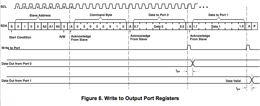
Working through the timing diagram one section at a time (open in another window if you want a bigger version to follow along), the slave address including the R/W bit is sent automatically by the Wire library when you call Wire.beginTransmission(address) . "Acknowledge from Slave" happens under the covers. The command byte is the address of the desired register, in this case 6 for the data direction register, which is transmitted by calling Wire.send(data) ; and again, the acknowledge happens automatically. Data to ports 0 and 1 is transmitted by calling Wire.send(data) for each byte desired. Finally, the transmission is terminated by calling Wired.endTransmission() .
Here's how it looks all put together in my code:
#define REGISTER_CONFIG (6)

void gpio_dir(int address, int dir) {
  //  Send config register address
  Wire.beginTransmission(address);
  Wire.send(REGISTER_CONFIG);

  //  Connect to device and send two bytes
  Wire.send(0xff & dir);  //  low byte
  Wire.send(dir >> 8);    //  high byte

  Wire.endTransmission();
}
Note that I'm sending the low byte first, then the high byte. I could just as well select the high byte of the configuration register (address 7) and transmit the high byte first, then the low byte, since the register address always toggles to the other byte of the current register. (It doesn't advance to the next register address as it does in some other types of chips.)
Having set the pins as outputs by calling gpio_dir(address, 0x0000), I can then output data on the pins with a gpio_write() function:
#define REGISTER_OUTPUT (2)

void gpio_write(int address, int data) {
  //  Send output register address
  Wire.beginTransmission(address);
  Wire.send(REGISTER_OUTPUT);

  //  Connect to device and send two bytes
  Wire.send(0xff & data);  //  low byte
  Wire.send(data >> 8);    //  high byte

  Wire.endTransmission();
}
Note that as these two functions are identical except for the target register address, they should really be abstracted into a gpio_register_write() function and two calls to the new function. For today, I just wanted to get a prototype up and running; for later, I'll build this into a proper object-oriented library that lets you create GPIO objects and call pinMode(), digitalRead(), and digitalWrite() on them like on the Arduino's native I/O pins (as well as still reading/writing them in bulk like I've done so far).
Do some I2C input
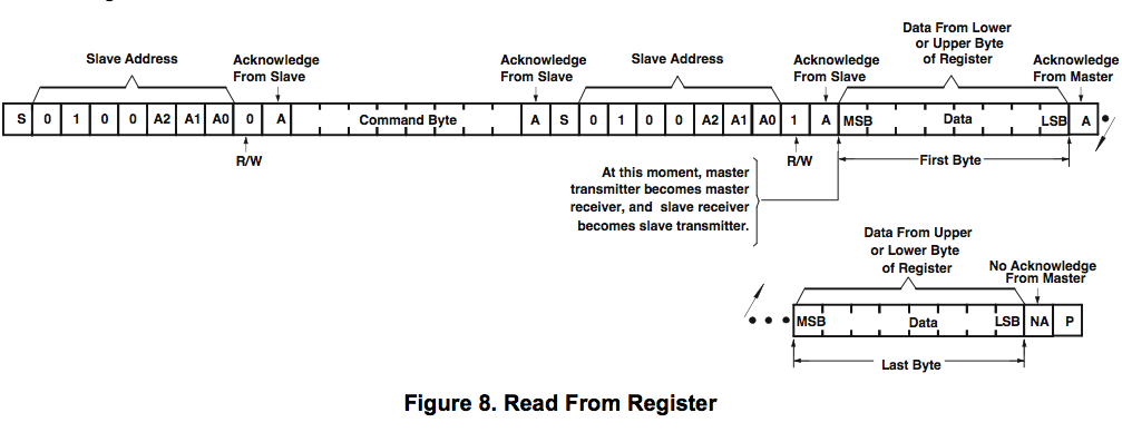
Assembly is the reverse of disassembly, right? Well, no. In order to read an input, you have to select the input register; and you select the input register by transmitting its register address.
So here's where I made mistakes five through sixteen; masked, of course, by the fact that I was transmitting to the wrong device address most of the time.
The first part is the same: send a device address by doing Wire.beginTransmission(address), and a register address (command byte) by doing Wire.send(data) . Then notice the "S" in there? That's another I2C start, i.e. Wire.beginTransmission(address) , and you have to do a Wire.endTransmission() first. (I tested lots of combinations before getting this right . . . and ultimately what I think I remember as my first hunch was correct, had I only been using the right device address at the time.)
Now send the device address again with another Wire.beginTransmission(address) , after which everything else is new. Instead of writing, we need to read; and the way to do that is Wire.requestFrom(address, numbytes) . (For the curious, as I understand it, the I2C master keeps clocking even during a read and the slave only manipulates the SDA line; so the master controls the number of bytes in the transfer and does need to know how many bytes are expected.)
Wire.receive() delivers the byte read from the wire, but the Wire library and the example code all show using if (Wire.available()) to check whether a byte was actually delivered before reading it. From my experimentation, I don't think this is actually implemented (or implemented correctly), and it's not like I can throw an exception if there's nothing there to read, but I'll go ahead and use it. (Laddie good boy!)
And here's mistake number somethin'-or-other (and the most embarassing one): Make sure that you actually return that value as the result of your function. If you just fall off the end of the function, you always get 0 back. Arrrrrgh.
All together now:
#define REGISTER_INPUT (0)

int gpio_read(int address) {
  int data = 0;

  //  Send input register address
  Wire.beginTransmission(address);
  Wire.send(REGISTER_INPUT);
  Wire.endTransmission();

  //  Connect to device and request two bytes
  Wire.beginTransmission(address);
  Wire.requestFrom(address, 2);

  if (Wire.available()) {
    data = Wire.receive();
  }
  if (Wire.available()) {
    data |= Wire.receive() << 8;
  }

  Wire.endTransmission();

  return data;
}
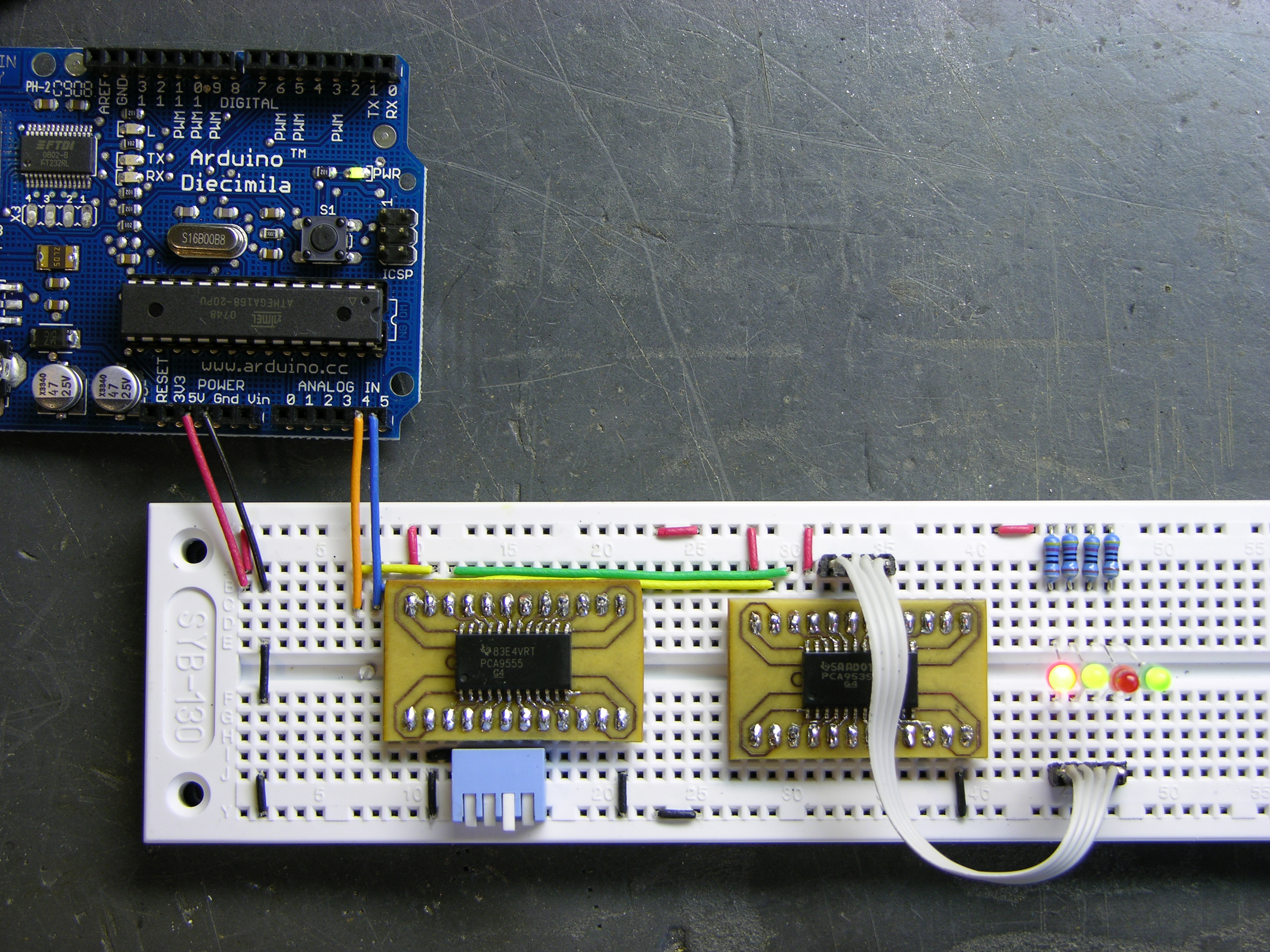
I/O Expansion in Action
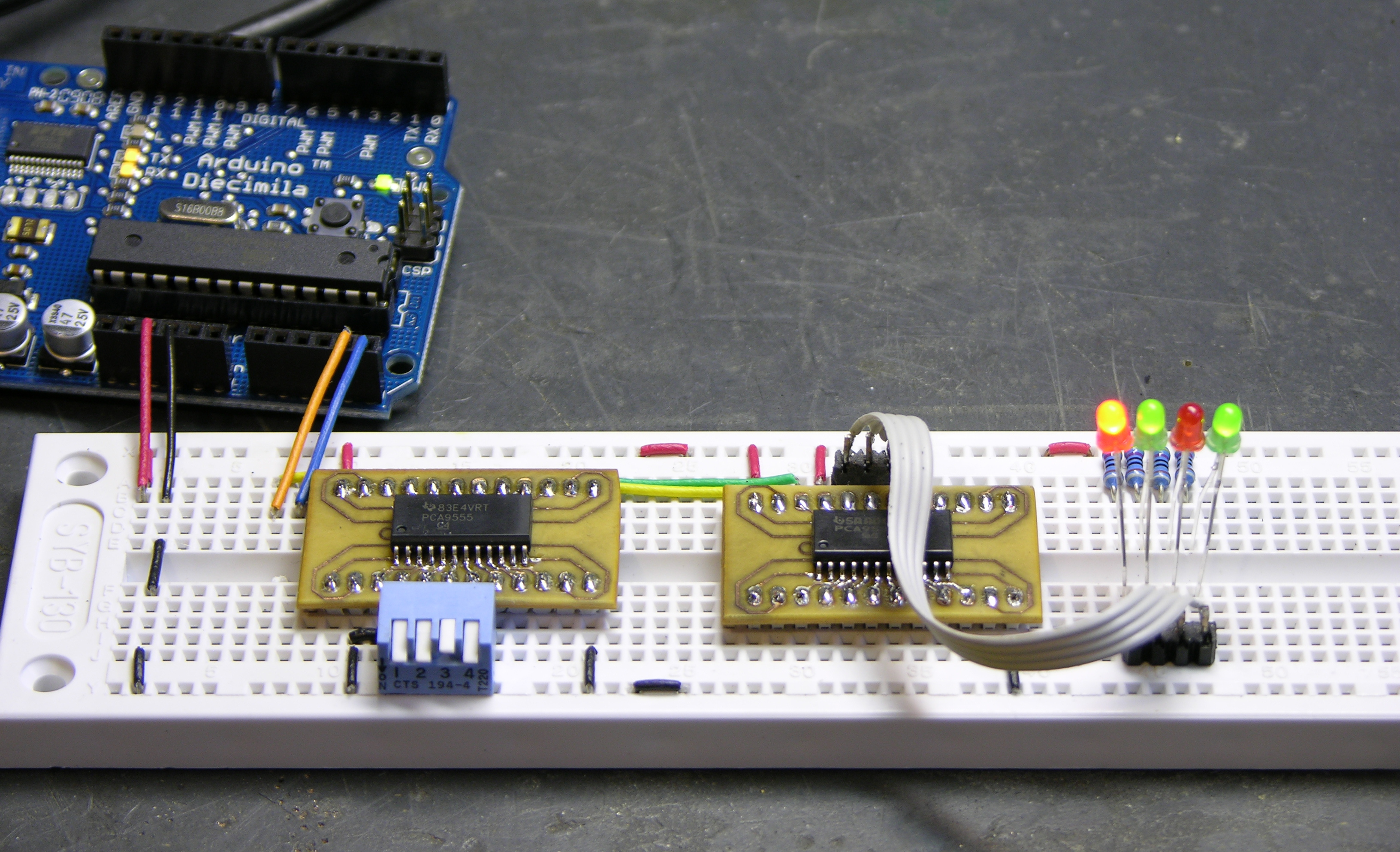
And thar she be. I'm reading a PCA9555 (has internal pull-ups) on the left with a DIP switch on port 0 pins 0-3 (left to right) and writing a PCA9535 (no pull-ups) on the right with LEDs on port 1 pins 4-7 (right to left). I deliberately put the LEDs on different pins of a different port in a different order to make sure I was successfully exercising every portion of the device. Flip the switches and turn the LEDs on and off, woo hoo, we're havin' some fun now!
All the Code
Here's the whole program: i2c_gpio.pde
I'll post a better version when I get it converted to a proper library.
So… i got a little lost reading your notes. Is this effectively the same as using a couple of multiplexers to read more than the available pins on the arduino? i recently did a pretty successful project where i was able to read 16 analog pins using only two of the analog pins directly on the arduino.
either way i enjoy your blog!
Seth, sorry, there’s a lot going on here, and I may not have done a very good job of putting it all down.
When you use multiplexers, you’re routing different signals to the Arduino to sample. With these expansion chips (which are digital, but there are I2C A/D converters available also) you’re actually taking the sample on the remote chip, then just sending the result back.
For inputs, there’s not a whole lot of difference in functionality, even though they’re implemented rather differently. You were probably using four digital pins to control the multiplexer, and for every additional power of two inputs you need another multiplexer control pin. With I2C, two control wires are all you need, no matter how many expansion chips you use (up to the limit of the system, which in theory is 127).
For outputs, you also gain the ability to drive many more outputs all at the same time. Again, there are multiplexing schemes for output LED driving, like row/column matrices and Charlieplexing. But those still involve at least one pin per power of two outputs (I2C still only two pins total); and multiplexed outputs flicker, which may (or may not) be okay for LEDs, but definitely isn’t okay for logic outputs to other equipment.
So, similar effect to multiplexing, different nuances. Does that help any?
Excellent tutorial.
I just used I2C to connect an Arduino (actually a BBB from Modern Devices) to an NS73M FM Stereo Transmitter module:
http://www.mikeyancey.com/FM-Stereo-Broadcaster.php
I had the additional factor of going from 5V to 3.3V; currently I’m using the simple Sensor Interface indicated in SparkFun’s Tutorial: http://www.sparkfun.com/commerce/present.php?p=Sensor-Interfacing
I’m still trying to find a nice looking enclosure to put it all in – it’s still spread out on a breadboard.
In the first section you send to the address REGISTER_OUTPUT and later to REGISTER_INPUT. I thought you said the Wire library handled the read/write bit automatically.
Mike, nice work on the transmitter! That looks great, and your Arduino code is very clean. Lucky you, you didn’t have to read from the device.
Michael, those are different layers of the protocol stack. The Wire library automatically sets the I2C R/W bit for whether we’re reading from the slave device or writing to it.
REGISTER_OUTPUTandREGISTER_INPUTare different registers within the slave device.keith that totally helps. in fact thats alot more interesting that multiplexing to my mind. does it have a similar effect on the arduino in terms of how much processor it uses? with my multiplexing setup once i got past 16 potentiometers the device slowed down significantly.
i have thought about building musical interfaces with upwards of 64 interface points and each with visual feedback (probably leds), and I have been wondering if my project has simply outgrown arduino in general.
ok, re-examining your code, i think i get it now. does the master not send the R/W bit till either Wire.send() or Wire.requestFrom() is called?
Seth, the slowdowns you see are probably a little bit more interesting than just sheer CPU. There are different ways to do A/D conversion, but the inexpensive ones tend to be fairly slow. I had to go to the ATmega (the microcontroller in the Arduino) datasheet to double-check this, but here’s what’s going on using the Arduino’s native A/D:
So probably (without actually looking at the source code) the Arduino’s
analogRead()function sets the internal multiplexer to pick the desired input pin, starts a conversion, and then busy-waits until the conversion is complete. Again I’d need to check the source code — or just runanalogRead()a few thousand times in a loop and see how long it takes — but my guess is it’s locking up the whole Arduino for 100μs (.1ms) every time you do ananalogRead().External A/D converters are probably faster (since the chips are built specifically for that single purpose); for example, I just looked at one with 2μs capture time. The problem is, you need to factor in the time to transfer the data back over the external bus (I2C). The chip I was looking at supports I2C fast mode up to 3+MHz data transmission, but the ATmega only supports 400kHz I2C data clocking. So if I guess at ten bytes on the bus in order to select an external A/D converter chip and channel and request a conversion, that comes to 200μs for the conversion — in the same ballpark as the Arduino’s own conversion. So unfortunately, that probably doesn’t help much.
Being stuck with the 400kHz I2C clock, the key would be to find an external A/D converter that minimizes the number of bytes that have to be transmitted across the wire. Things I’d look for in this regard would include:
If you could find a converter that would output all channels’ data in a single bulk read operation, you could get down to maybe 2.5 bytes on the wire per channel, or 50μs per conversion.
Any real engineers out there want to take a stab at this?
Michael wrote:
That’s a very astute observation, and I hadn’t paid attention to that until you pointed it out. The question, rephrased, is does the master really write the seven slave address bits on the wire when
Wire.beginTransmission()is called and then hold indefinitely until it finds out whether a read or write operation is requested?The real answer lies within the Wire library, but I don’t have time or inclination to read it right now, so I’ll speculate: My guess is that
Wire.beginTransmission(address)caches the target address in the library and sends the bus START bit, and then nothing further happens with the hardware untilWire.send()orWire.requestFrom()is called.This is based on the ATmega168 datasheet’s description that a user application writes the microcontroller’s TWCR register to send the I2C START bit, then loads the slave address + R/W into TWDR and writes TWCR to send the slave address. That is, slave address + R/W mode get appended into a single ATmega register.
In other words, the Wire library encapsulates the I2C operations in a way that’s, shall we say, syncopated from the sequences of the underlying hardware. That seems very strange to me — but then the Wire functions already seemed very strange to me.
I guess it’s time to go to the source code. I’ll read through Wire when I have a little more time and follow up here.
cool, thanks for the clarification. another question for you, are you sure you have to do a Wire.endTransmission() before calling beginTransmission() for the read request? wouldn’t that generate a Stop condition, when what we really want is just another Start?
I agree that we don’t want/need a Stop there, just another Start; and the underlying hardware supports transmitting another Start without a Stop. However, I thought I tried all the combinations and this was the only one that worked.
I’ve just barely started to browse
Wire.cpp, and what I see is wrapper functions that are stuffing variables and buffers for calls to the underlying twi library, which may be running non-stop in an interrupt handler.twi.cappears to have a much more straightforward match between its functions and the underlying operations, and not everything you can do in twi appears to have been pulled up into Wire.In short, Stop / Start may be the only way to get a re-Start in Wire, and I’m lucky it works with my chip because it shouldn’t.
More later.
my own examination of Wire.cpp revealed that nothing is done on the wires until endTransmission() is called, except in Slave mode. line 117 (for me) is where twi_writeTo is actually called, all the other functions in Wire.cpp just prepare for that calling by loading the variables.
Sir:
I have been wrestling/struggling/pulling my hair out with the Wire library for a month or so now. I have posted about my latest difficulty on the Arduino forums – I was wondering if you’d be kind enough to look at my code there and see if you can determine what I’m doing wrong.
Thanks, Scott.
(the post is at http://www.arduino.cc/cgi-bin/yabb2/YaBB.pl?num=1212368382)
Scott, I’m wrestling with Arduino I2C and a 24LC08 EEPROM myself, so I feel your pain.
Looking at your code, I see two things that don’t seem to gibe with the datasheet. I can’t guarantee they’re important because I don’t have my own working yet, but they should be easy to test.
First, the datasheet I’m looking at says the 24LC00 does not advance the address pointer after a write, so there is no bulk write mechanism on that chip. (There is bulk write on other chips in the series, to be sure.) So where you’re sending three 2s in a row, each allegedly (per the datasheet) overwrites the data buffer for the same location. This shouldn’t cause an error, but is probably not what you intended.
Second and more serious, the EEPROM needs some time to process the write command. If you had access to the low-level I2C, you could send further write commands and check whether slave acknowledge is returned in order to test when the write is complete, but the Wire library masks such details (and I haven’t read twi closely enough yet to know whether you can check such things in there, although as you can see Michael and I are starting to dig into it).
In any case, I’d suggest at least as a test putting an absurdly long delay after the writes and before the reads, and see whether it makes any difference to give the chip time to complete its long write operation before you’re trying to read it. Like, start with
delay(1000), and if it fixes the problem, work down to the smallest value (datasheet says 4ms) that works reliably. I can imagine that trying to read while it’s still performing a commit could make it do odd things.Again, no guarantee that this will get you anywhere because I don’t have mine working yet, but it’s a start. I’m interested in getting this going too, so I’ll be very happy to work through it with you.
#define DIP_ADDRESS (0×4 3 | 0×7)
Shouldn’t these both be 0×4 < 3?
Kenneth, good catch. At some point in my original editing, I think I was using <code> tags instead of the <pre> tags I ended up with, and WordPress’s HTML parser ate some of my symbols (as it did yours, in your comment).
It’s fixed now. Thanks!
You can easily do these port-expansions with 74xx595 and 74xx165 using SPI. They don’t support “true” SPI, with a Slaveselect line, but you can easily use them via the AVR SPI interface. You also can chain multiple 595 or 165 together to save io-pins. The pro for using SPI is that it works a lot faster than I2C (maximum for AVRs is CLK/2) and they are cheaper than I2C chips and usually easily available even in DIP-packages. Their biggest con might be that they only provide 8 outputs, which requires a bit more wiring.
Nico, certainly you can do port expansions with either I2C or SPI.
For the project I’m helping with, we didn’t want to give up as many digital lines as it would take to drive all the slave selects. The I2C chips also offer the ability to mix inputs and outputs within a single chip rather than requiring two chips side by side, so they were a good fit for us. But I have nothing against SPI for other applications.
Hi,
I have small doubt, If we want to write to an output port can we read from the Input Port register with out configuring it as Input Port ?
Limousine
Limousine, I don’t understand what you’re asking. Can you say more about what you’re trying to do?
hi !
you mentionned you did try the I2C EEPROM.
did you manage to have it working.
I am trying (hard) since last week without no success !
i manage to receive bytes from the eeprom but totalyy inconsistant with the datasheet !
I you could post some of your code for I2C EEPROM that would be cool !
olivar
Olivar, no, I haven’t gone back to the EEPROM yet. I thought I had seen examples from people who had that working, but I can’t find them now. Maybe check on the Arduino playground when their site is accessible again? (It isn’t for me now, and often.)
keith,
thank you
I got the EEPROM working last night !
I follow what you said about 7 bits device address
the EEPROM (1 Mb from microchip) has B10100000 (0xA0)
so I used B1010000 (0×50) !
as soon as I get a decent piece of code (for now it is very messy), I’ll post it to you
many thanks
olivar
For the record — I found the Arduino playground I2C EEPROM entry.
thanks
this work as long as you use device address = 0×50 (block 0) and 0×54 (block 1) for microchip 24AA1025 EEPROM.
now I have trouble getting the midi sysex from my synth to the memory and back to the synth on a reliable way…
I put a 5 ms delay between each write but not good enough…
code eat sleep code…
Keith,
You seem to know what you’re doing. I don’t. But I know what I want to do. I’m using the arduino diec. with this device: http://www.maxim-ic.com/quick_view2.cfm/qv_pk/3023
It’s an I2C Real time clock (2 free samples from Maxim/Dallas semi!)
I want to write a sketch obviously to read the time registers, and also to write to them (eventually with a 3-button menu and 16×2 LCD) anyway, I so lost in the format of talking to these things. Any help is greatly appreciated…
Nick, I’ve worked with a Dallas RTC chip using SPI before, but not using I2C. And the killer about working with these chips is that you have to get your I2C working (which can be tricky) and correctly manipulate the chip’s register set (which can be tricky) before you see any results at all.
My suggestion would be to write code to read just the seconds register and display the result over the (virtual) serial connection. That should be a relatively small task; but even without being able to set the time yet, you should know when you reach success because the returned value increments every second. Once you have that working, expand to reading the whole thing, then setting the time and using the SRAM.
Nick, have you looked at the datasheet for that part? The entire part is 3mm across! That’s f***ing impossible to use. What you probably want is a DS1306, which is what I used making my clock.
http://kennethfinnegan.blogspot.com/2008/07/tying-it-all-together-into-clock.html
http://kennethfinnegan.blogspot.com/2008/07/initial-work-with-ds1306.html
Kenneth, I think the package makes the MAX6900 sound exciting to use and fun to solder . . . but then my wife does like to point out that I’m an atypical consumer.
Certainly it means you have to build a breakout for breadboarding.
Yeah, I have purchased the SOT23 to DIP adapter board and successfully soldered (I think). I kinda know it’s ok because after some messy sketching and removeing the SDA and SCL the data either changed or ceased. My problem is the intializing the chip as Keith pointed out, to respond to I2C and provide data from the called register. A sample sketch to read just the seconds register would probably set me on the right path. I like the part’s size for my particular application. Somebody learn me somethin’… The example libs in arduino have serial sketches ‘master read’, ‘slave recieve’, etc. But I just am clueless on how to set the addresses and talk to this little guy.
Ledent Francois wrote:
Hello,
I just read your page: http://www.neufeld.newton.ks.us/electronics/?p=241
and I would like to know if it would be possible to use the Wire library to
connect a Xbee module ?
My goal would be to add a Xbee module(UART) to a board having I2C/RS232
connection.
Thanks,
Francois
Student Belgium
Francois, I don’t have any experience with XBee, but I’m very interested in learning more. When you get it working, please come back and post a link to your project!
I am currently working on a single PCA9552 with an Arduino which should be very similar to your setup. I just soldered one LED on the 9552 LED0 Pin and wanted just to toggle the LED but it’s always on. It get disabled when I change REGISTER_CONFIG to 7.
Maybe it can be solved, when I understand what happens in the part of the gpio_write function:
Wire.send(0xff & data); // low byte
Wire.send(data >> 8); // high byte
what kind of ‘data’ do I need to enable the LED and which to disable?
Thanks
Christian
Christian, the data in this function is the sixteen bits of data I’m sending to the GPIO chip’s output lines. I was connecting my LED to V+ and the 9535; so I set the corresponding bit to 0 to drive the output low and light the LED.
Have you checked the 9552′s datasheet against the 9535/9555 to see if the register set is the same? If so, I have a proper GPIO Arduino library that I haven’t posted yet (still some polishing to do) that is nevertheless usable and which could save you a ton of work.
Well the chips in some cases but I think it shouldn’t be that difficult to change the corresponding parts. It would be nice if you can post your library. Until then I try to understand that whole I2C thing, maybe that solves the problem. I just don’t get what the wire library is doing for me and what I still have to do, since the datasheet is having the information for programming from scratch of course.
Christian, have you checked the 9552′s datasheet against the 9535/9555 to see whether the register set is the same? If it’s the same, then my functions will work on your 9552. If it isn’t, my functions won’t help.
The Wire library is how you control the Arduino’s I2C interface. Without it, you can’t get onto the I2C bus to talk to your other chips.
hi Keith,
I’m trying to interface and i2c-16io board to arduino. I want to connect all ports to input switches. Below is the code I wrote;
#include
byte x=0;
void setup()
{
Wire.begin();
Serial.begin(9600);
}
void loop()
{
Wire.beginTransmission(0×40);
Wire.send(0×00);
Wire.send(0×01);
Wire.endTransmission();
delay(10);
Wire.requestFrom(0×40,1);
while(Wire.available())
{
x= Wire.receive();
Serial.print(x);
}
Serial.print(x);
delay(10);
}
So far no results. I tried and tried so much that I don’t know what else to do. Your here is appriaciated.
Thanks
Kenneth
Kenneth, I don’t know what an i2c-16io board is, and I expect I’d have to do as much work to get it to work with the Arduino as I did these PCA9535/9555 chips. I probably can’t be much help here.
Keith,
The i2c-16io is a breakout box of the PCA9535. I tried your code making some modifications to read data on serial. I must also admit that I’m a total newbie and didn’t understand your code in full.
Confusing is that the manufactorer claims that address code is 0×40, 0×41 (8bit) while you claim the Wire library uses (7bit).
Anyway, if you can help I just need to read 16 switches on this chip to arduino. I really tried so much and I’m almost ready to quit!
Thanks
Kenneth
Kenneth, the low bit of the I2C address on the wire is the R/W bit. The address as used in the microcontroller is seven bits.
When I Google for i2c-io, the second hit I see is an Arduino sketch from Gravitech that purports to make it work. I’d suggest trying either their sketch or mine, unmodified except for making the address match how you have your chip’s address jumpered.
Keith,
Oley… it worked. Thanks for your tip. Never noticed this website before and I did spend a lot of time (DAYS) searching for some usefull codes. To be onest I didn’t search for i2c-16o…stupid me!
Thanks once again
Kenneth
I’m looking for I2C Sensors like SHT75
Can you tell me where can i find and buy some others
Thanks
Jon, octopart.com suggests Farnell and Newark.
Can you please explain what you are sending in the following lines:
Wire.send(0xff & data); // low byte
Wire.send(data >> 8); // high byte
if data = 11111111 11111111
it looks like the second byte is being sent first
and the first byte is being sent second, is there a reason behind this, or am i horribly confused?
Justin, I do explain that, a couple of paragraphs below Figure 6. These chips have the low byte at a lower-numbered register address than the high byte, so the low byte needs to be sent first.
So is that the same no matter what the “data” is?
Justin, if you’re referring to this chip, you can do it either way. As noted above, it automatically toggles between the high and low bytes of a given register. So you can go to register index 6 and write (low, high); or you can go to index 7 and write (high, low).
If you’re referring to a different chip, you’d have to look at its datasheet and see how its registers are laid out.
Ok, may i’m just confused on what the LOW and HIGH bytes are. What exactly is a low or high byte? Maybe that will clear things up.
Keith, your blog is great, it helps me a lot to clear concepts.
I’m trying to connect Arduino with a MCP23016, i2c expander without results.
I’m using a Duemilanove board, and arduino 013 in linux (ubuntu).
My dubs are:
The datasheet says that the address of mcp23016 is 0100000, so to write i have to user 01000000 (0×40) and to read 01000001 (0×41), with the Wire library I should use 0100000 (0×20) to write?
My code:
#include
#define MCP23016_I2C_WRITE 0×40
#define MCP23016_I2C_READ 0×41
#define MCP23016_I2C 0×20
#define VALOR 0xff
void setup() {
Serial.begin(9600);
Wire.begin();
}
void loop() {
//test();
delay(1000);
test2();
}
void test2(){
Serial.print(“Direccion:”);
Serial.print(MCP23016_I2C);
Serial.print(” Registro:”);
Serial.print(GP0);
Serial.print(” Valor:”);
Serial.println(VALOR);
Wire.beginTransmission(MCP23016_I2C);
Wire.send(GP0);
Wire.send(VALOR);
Wire.endTransmission();
}
Any suggestion is welcome.
Fernando, some of your code got lost thanks to HTML conversion. If you need to paste more code, you should do it like this:
<pre>
code here
</pre>
Sorry about the hassle.
Do you have all of your address inputs tied low so you know for sure this is at the low device address?
The datasheet is listing the device base address as a 7-bit value (0×20); so yes, I believe that’s what you’ll use as the I2C address for the wire library.
You don’t say what you’re trying to do and what’s happening instead, which makes this difficult to debug. But it looks as though you’re trying to write a value to the I/O register hoping to get a change on the pins; yet (in the code that made it through the HTML mangling) you haven’t set the I/O direction. The datasheet says the pins are set to inputs on power-up, so you’ll probably need to set the I/O direction register to outputs first.