Cort and I are good friends and both interested in electronics, but have had surprisingly little opportunity to work on electronics together. He’s an amateur radio operator and very much into RF design, and I’m more interested in physical computing.
So when he started describing his receiver voter project and suggesting that I might be able to help out on some of the digital interfacing, I jumped at the opportunity. A radio repeater receives transmissions at one frequency and rebroadcasts them at a nearby frequency, effectively boosting the signal (by repeating it) without increasing transmission power over the legal limit.
The voter picks the best signal from several different receivers (possibly several miles apart, linked back to the repeater base) and routes it to the repeater. And Cort’s voter will have lots of pushbuttons, LEDs, and digital controls — more than he could wire directly to the Arduino he’s planning to use to control it.
That’s where I come in. Cort is very interested in learning the Arduino, but he hasn’t done much with microcontrollers lately and is to some extent playing catch-up with a decade’s worth of advances in technology. So I’ll pitch in and give him some ideas and programming assistance on the digital I/O.
I2C I/O Expansion
I started by looking for digital I/O expansion chips, and I did not start by looking for I2C. I’ve never worked with I2C before and I thought I’d find something with SPI, but oh no, that was not to be the case. Nearly everything I could find — and everything I could find that was readily available and affordable — used I2C. This is actually a good thing — I2C uses only two interface pins to talk to up to 127 devices, and SPI needs two pins for the bus plus a separate chip select line for each device — but it wasn’t what I was hoping for when I started looking.
So I ordered some samples, warmed up by trying to interface to an I2C EEPROM I had lying around (with no luck whatsoever, although I now know several things I did wrong and will go back to it soon), built some breakout boards, and got I2C communications up and running on the Arduino this weekend.
And the number of mistakes I made along the way was staggering. Not just little misunderstandings, but mind-numbing stupid mistake after stupid mistake, things I’ve know better since I was six. With a weekend like this, it’s a wonder I haven’t run over myself with my own car somehow.
So do what I say, not what I did.
Arduino I2C
First off, I had to get the Arduino talking to I2C. There’s not much online about doing I2C on the Arduino, and the most useful for me was Julian Bleecker’s blog post prosaically entitled Arduino and the Two-Wire Interface (TWI/I2C) Including A Short Didactic Parenthetical On Making TWI Work On An Arduino Mini.
It turns out there’s a Wiring library called Wire (why not, oh, say, I2C???) that operates the ATmega’s hardware I2C port and which has been incorporated into the Arduino software since version 6, so everything I needed was right there; I just had to figure out how to hook it together.
Between the Wire documentation being sketchy and not explaining how each function corresponds to an I2C function, its code examples being outdated and occasionally incorrect, my lack of familiarity with I2C in general, my not yet having a working I2C circuit to reference, and of course my many, many mistakes, this made for a bit of a vexing experience.
Let’s do it.
Give up analog pins 4 and 5
Analog pin 4 doubles as the I2C SDA (serial data) pin, and analog 5 doubles as SCL (serial clock), so you don’t get to use them any more. I like to put a comment at the top of my code to remind myself which pins I’m using and what they should be wired to, so:
/******************************************************************************
 *  i2c_gpio
 *  Keith Neufeld
 *  May 26, 2008
 *
 *  Prototype I2C interface to TI 9535 and 9555 GPIO expanders.
 *
 *  Arduino analog input 5 - I2C SCL
 *  Arduino analog input 4 - I2C SDA
 *
 ******************************************************************************/
Pull the Wire library into your project
#include <Wire.h>
This gets you declarations for the functions you’re going to be using, and magically tells the linker to look in the Wire library for functions you’ve referenced.
Set your I2C device address(es)
I’m an old C programmer, so I like to #define constants at the top of my program rather than hard-code them where they’re used. And the parens around each definition protect it from order-of-operation errors, since #defines are substituted lexicographically by the preprocessor, with no intelligence whatsoever about your intentions. (If this doesn’t make sense, don’t worry about it and just remember to put parentheses around numerical and variable #define substitutions.)
//  I2C device address is 0 1 0 0   A2 A1 A0
#define DIP_ADDRESS (0x4 << 3 | 0x0)
#define LED_ADDRESS (0x4 << 3 | 0x7)
[Update 03-Jun: The WordPress HTML monster ate my operators! Corrected DIP_ADDRESS and LED_ADDRESS to both be
<< 3 . Thanks, Kenneth!]
An I2C device address is seven bits. The I2C section of your datasheet will talk about the eight-bit address byte including the data direction bit (R/W), but this is a trick. ("Get an axe.") The Wire library will take care of the data direction bit for you automatically on each operation you perform, so you need to give it only a seven-bit address.
In my prototype, I'm using two different chips with the first four device address bits "burned in" at 0100 and the last three bits controlled by address pins on the chip, so you can use eight of these on one bus. I have one with all the address pins tied to ground (000) and another with all the address pins tied high (111), and I'm "OR"ing together the burned-in fixed bits and the values that I have the variable bits set to.
First mistake: Make sure you know how to convert from binary to hex (or decimal). It turns out that binary 0100 isn't hex 0x8, and it also turns out that the chips don't respond to an address that isn't their own. Seventeenth mistake: Make sure you remember how many hardware address lines you have. It turns out that binary 111 isn't hex 0x3, and it also turns out that chips don't respond to an address that isn't their own.
Sigh.
Initialize the Wire library
void setup() {
  // ...
  Wire.begin();
  // ...
}
Wire.begin() initializes the Wire library as an I2C master and reconfigures analog pins 4 and 5 as I2C pins. Wire.begin(address) (not used here) initializes the Wire library with the Arduino functioning as a slave at address address, useful if you want to use the Arduino as an I/O expander for another Arduino, build a BlinkM, or something like that.
Do some I2C output
From here on out, everything is specific to the device you're trying to control. Since I went 'round and 'round (what comes around goes around, I'll tell you why) on this before I got it working, and you probably won't be using exactly the same chips I am, I want to go through the datasheet and talk about how to translate the timing diagrams (correctly) into Wire code. And I'm going to cover writing to the device first, because curiously that's easier than reading.
One thing that's important to keep in mind throughout is which level we're discussing at any given time. Transmitting on the I2C bus is not the same as writing to a bus device's registers, which is not the same as causing a device to output on a pin. Unfortunately, all of these are called "write" by different documents in different contexts.
My samples that arrived first are Texas Instruments PCA9535 and PCA9555 16-bit I/O port expanders, so that's what I'm using. These chips give you sixteen additional digital I/O lines; you just supply power, three configurable address lines, and I2C. The chips are identical except that the 9555 has internal pull-up resistors, so I'm using the 9555 for inputs and the 9535 for outputs (where the pull-up is unnecessary and would add to the power draw when outputs are low).
The chips have eight one-byte registers, divided into four pairs for the sixteen bits' worth of input, output, polarity inversion, and data direction. To output data on the chip's pins, configure the pins as outputs by writing 0s into the data direction registers (they default to inputs), then write data to the output registers. To write to a register, send the chip the register address followed by the desired data. A write to one byte of a two-byte register pair toggles the register address to the other byte of the pair, so we can write both registers of a pair consecutively (in either order) without retransmitting the register address in between.
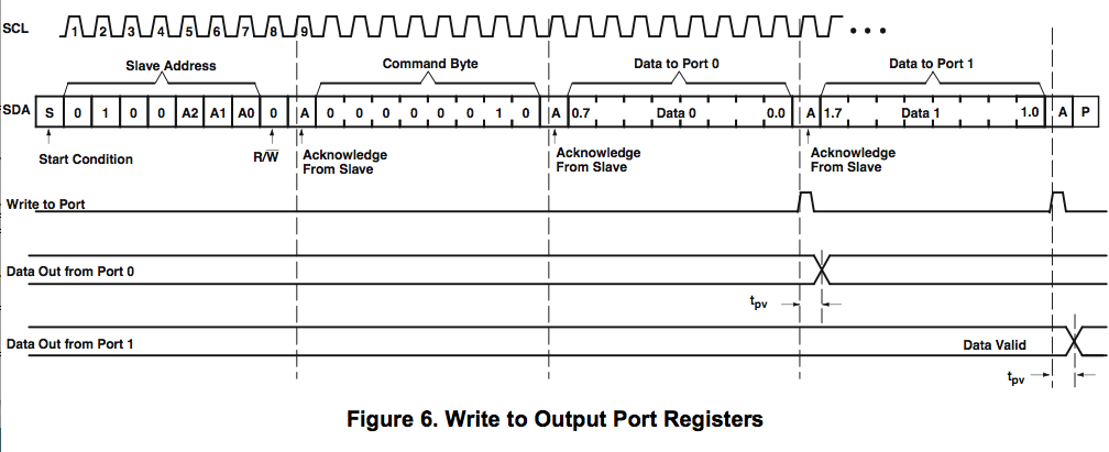
Working through the timing diagram one section at a time (open in another window if you want a bigger version to follow along), the slave address including the R/W bit is sent automatically by the Wire library when you call Wire.beginTransmission(address) . "Acknowledge from Slave" happens under the covers. The command byte is the address of the desired register, in this case 6 for the data direction register, which is transmitted by calling Wire.send(data) ; and again, the acknowledge happens automatically. Data to ports 0 and 1 is transmitted by calling Wire.send(data) for each byte desired. Finally, the transmission is terminated by calling Wired.endTransmission() .
Here's how it looks all put together in my code:
#define REGISTER_CONFIG (6)

void gpio_dir(int address, int dir) {
  //  Send config register address
  Wire.beginTransmission(address);
  Wire.send(REGISTER_CONFIG);

  //  Connect to device and send two bytes
  Wire.send(0xff & dir);  //  low byte
  Wire.send(dir >> 8);    //  high byte

  Wire.endTransmission();
}
Note that I'm sending the low byte first, then the high byte. I could just as well select the high byte of the configuration register (address 7) and transmit the high byte first, then the low byte, since the register address always toggles to the other byte of the current register. (It doesn't advance to the next register address as it does in some other types of chips.)
Having set the pins as outputs by calling gpio_dir(address, 0x0000), I can then output data on the pins with a gpio_write() function:
#define REGISTER_OUTPUT (2)

void gpio_write(int address, int data) {
  //  Send output register address
  Wire.beginTransmission(address);
  Wire.send(REGISTER_OUTPUT);

  //  Connect to device and send two bytes
  Wire.send(0xff & data);  //  low byte
  Wire.send(data >> 8);    //  high byte

  Wire.endTransmission();
}
Note that as these two functions are identical except for the target register address, they should really be abstracted into a gpio_register_write() function and two calls to the new function. For today, I just wanted to get a prototype up and running; for later, I'll build this into a proper object-oriented library that lets you create GPIO objects and call pinMode(), digitalRead(), and digitalWrite() on them like on the Arduino's native I/O pins (as well as still reading/writing them in bulk like I've done so far).
Do some I2C input
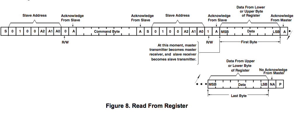
Assembly is the reverse of disassembly, right? Well, no. In order to read an input, you have to select the input register; and you select the input register by transmitting its register address.
So here's where I made mistakes five through sixteen; masked, of course, by the fact that I was transmitting to the wrong device address most of the time.
The first part is the same: send a device address by doing Wire.beginTransmission(address), and a register address (command byte) by doing Wire.send(data) . Then notice the "S" in there? That's another I2C start, i.e. Wire.beginTransmission(address) , and you have to do a Wire.endTransmission() first. (I tested lots of combinations before getting this right . . . and ultimately what I think I remember as my first hunch was correct, had I only been using the right device address at the time.)
Now send the device address again with another Wire.beginTransmission(address) , after which everything else is new. Instead of writing, we need to read; and the way to do that is Wire.requestFrom(address, numbytes) . (For the curious, as I understand it, the I2C master keeps clocking even during a read and the slave only manipulates the SDA line; so the master controls the number of bytes in the transfer and does need to know how many bytes are expected.)
Wire.receive() delivers the byte read from the wire, but the Wire library and the example code all show using if (Wire.available()) to check whether a byte was actually delivered before reading it. From my experimentation, I don't think this is actually implemented (or implemented correctly), and it's not like I can throw an exception if there's nothing there to read, but I'll go ahead and use it. (Laddie good boy!)
And here's mistake number somethin'-or-other (and the most embarassing one): Make sure that you actually return that value as the result of your function. If you just fall off the end of the function, you always get 0 back. Arrrrrgh.
All together now:
#define REGISTER_INPUT (0)

int gpio_read(int address) {
  int data = 0;

  //  Send input register address
  Wire.beginTransmission(address);
  Wire.send(REGISTER_INPUT);
  Wire.endTransmission();

  //  Connect to device and request two bytes
  Wire.beginTransmission(address);
  Wire.requestFrom(address, 2);

  if (Wire.available()) {
    data = Wire.receive();
  }
  if (Wire.available()) {
    data |= Wire.receive() << 8;
  }

  Wire.endTransmission();

  return data;
}
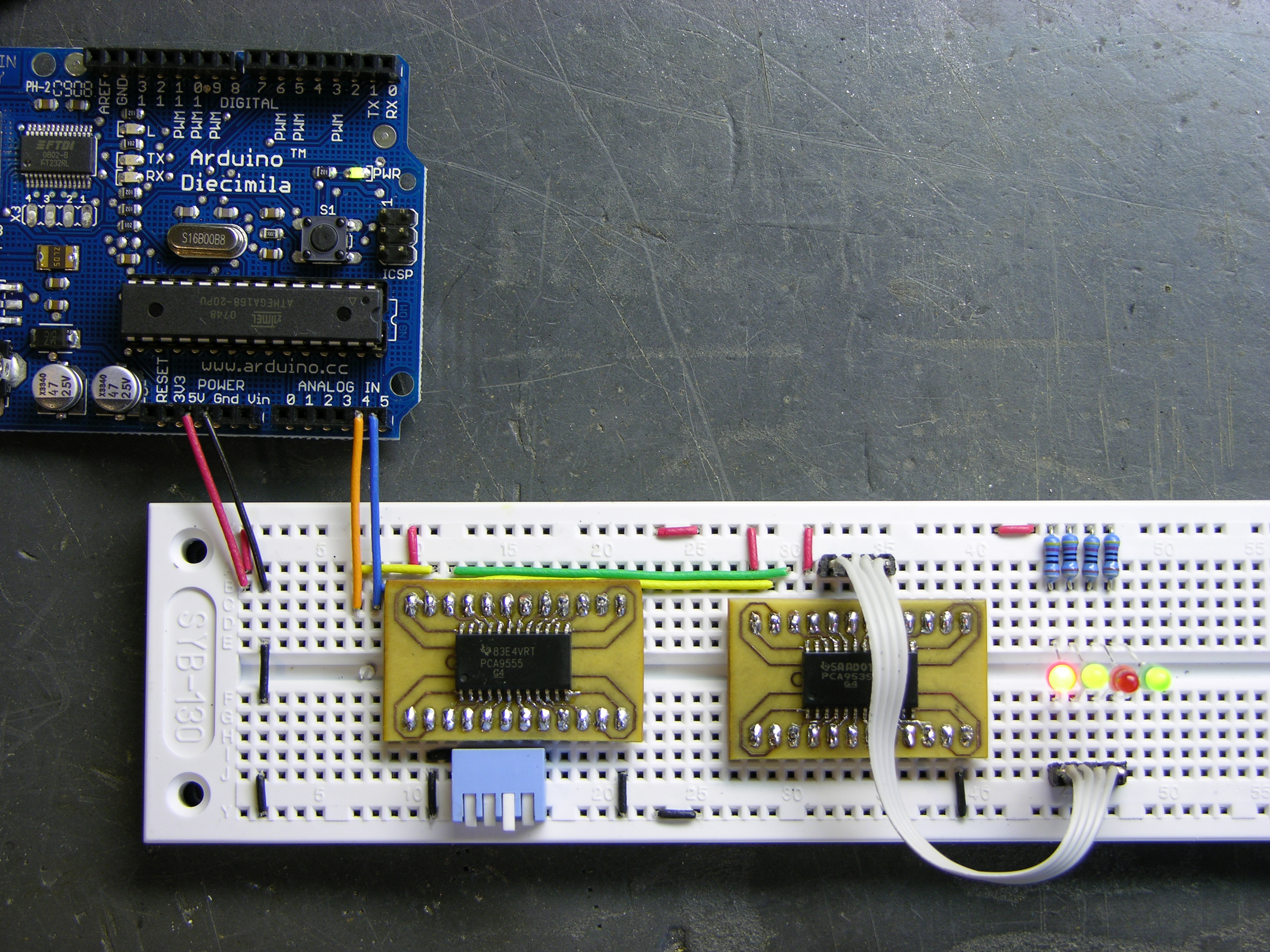
I/O Expansion in Action
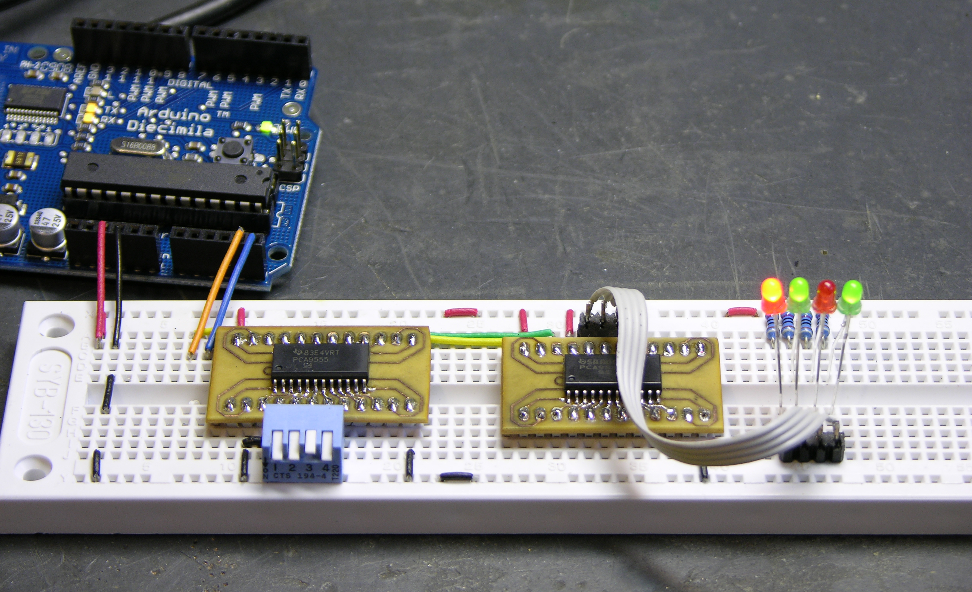
And thar she be. I'm reading a PCA9555 (has internal pull-ups) on the left with a DIP switch on port 0 pins 0-3 (left to right) and writing a PCA9535 (no pull-ups) on the right with LEDs on port 1 pins 4-7 (right to left). I deliberately put the LEDs on different pins of a different port in a different order to make sure I was successfully exercising every portion of the device. Flip the switches and turn the LEDs on and off, woo hoo, we're havin' some fun now!
All the Code
Here's the whole program: i2c_gpio.pde
I'll post a better version when I get it converted to a proper library.
Keith, thanks for your time, I trying to activate 16 relays with Arduino (for control the irrigation system of my home).
I’m using a ZX-Relay16 board (http://www.inexglobal.com/products.php?type=addon&cat=app_control&model=zxrelay16), this use a MCP23016 to interface I2C with 2 ULN2803 that drives the relays. The board if feed by a 12v adapter.
I’m connecting Arduino to USB and to connect both boards I did:
- ZX: SDA GND -> 4.7 K resistor -> Arduino GND
- ZX: SCL GND -> 4.7 K resistor -> Arduino GND
- Arduino analgo pin 4 ->ZX SDA
- Arduino analgo pin 5 ->ZX SCL
If I connect Arduino 5v to ULN2803 I get the relays working. So I supouse that my proble is with the MCP23016.
Before run the program I have HIGH in SDA and SCL of MCP23016, running the program I have a pulse in both and nothing else.
Any suggestion is very welcoming.
#include
#define MCP23016_I2C_WRITE 0×40
#define MCP23016_I2C_READ 0×41
#define MCP23016_I2C 0×20 //the library adds last bit.
#define GP0 0×00 //register
#define VALOR 0xff //all to high
void setup() {
Serial.begin(9600);
Wire.begin();
}
void loop() {
//test();
delay(1000);
test2();
}
void test2(){
Serial.print(”Direccion:”);
Serial.print(MCP23016_I2C);
Serial.print(” Registro:”);
Serial.print(GP0);
Serial.print(” Valor:”);
Serial.println(VALOR);
Wire.beginTransmission(MCP23016_I2C);
Wire.send(GP0);
Wire.send(VALOR);
Wire.endTransmission();
}
IT’S WORKS!!!!
What stupid thing, the problem were the resistors, I’m using a board with relays and mpc23016, seeing the diagram again I saw that already had the pull up resistors in SDA and SCL, so I removed my resistors and WORKS.
Thanks for your time and patience.
Keith,
a nice entry – it got me started on my I2C project. I have a few suggestions/bugfixes:
1) The receiving part should NOT start with beginTransaction() – the beginTransaction/endTransaction part is ONLY used to write data to a slave. As was noted here in fact nothing happens until you call endTransaction() at which point the collected data is transmitted. So your code above in fact sends two write requests – one with the data and one with 0 bytes just after you read (I’m using this for a network of Arduinos, that’s how I noticed first).
2) Wire supports multi-byte sends, so if you have a little-endian device, you can as well use
int myValue;
…
Wire.send((byte*) &myValue, sizeof(int));
This is useful especially in slave responses, which go on the wire right away so it’s more efficient.
Thanks again,
Simon
I need to get i2c working with an Arduino Duemilanove. Has anyone done this yet? Any gotcha?
Ken, yes, I’m using a Duemilanove board, no problems with I2C.
Thanks for the great article! I hooked up a robot-electronics LCD03 LCD display to my Arduino Nano tonight, and got it working well in the end. I was stumped for a while though, and it was all related to the 7 bit addressing. The LCD03 is documented to be at 0xC6, and I misunderstood how to turn that into a 7 bit address. I though taking the top bit off would be correct (i.e. 0×46). It turns out I was completely wrong, and it had to be the bottom bit (i.e. 0xC6 >> 1 which is 0×63). Anyhow, it’s working great now.
Hey Keith-
Thanks for the helpful blog. I am trying to use the arduino Duemilanove to run a MAX6953 LED driver with I2C. I am an electronics newbie and having trouble figuring out the 7 bit addressing. Can you offer some guidance?
Here’s is the chip I am using
http://datasheets.maxim-ic.com/en/ds/MAX6953.pdf
Hello!
Having just obtained one of these darlings I decided to try my luck, so far most of the ones I’ve done work. My next gamble will be using I2C for talking to logic.
Would any of you know if these guys, such as the Duemilanove will talk to the PCF8574A, it’s in the same family as the pair used for the excellent demo above. I should also mention that I’ve ordered samples of the parts listed above, plus two others.
Is I2C fast enough for real-time computing? I want to control a BLDC motor with an Arduino and send some data out to my laptop, or perhaps to another Arduino, during each control loop. The communication has to be fast, so the motor commutation doesn’t get delayed. How many clock cycles does it take to send a few bytes through I2C? Would it be better just to use the regular serial communication provided by the Arduino?
Thanks!
David, the Arduino’s library does the slower 100kHz mode by default and the ATmega’s I2C can run at 400kHz. Here’s an Arduino forum post on switching to the higher speed.
It sounds like you’re saying you want to communicate with something else while the motor control is happening. Understand that I2C writes generally happen by stuffing the write buffer and then letting the microcontroller’s hardware do the actual transmission. You can examine the Wire library source code to see how many instructions are involved in priming the transmit buffer.
April, my apologies for not responding sooner. Your question got lost amidst a flood of other comments and comment spam.
The datasheet lists the 7-bit address as 101XXXX, with the four bits set by tying the two address lines to GND, V+, SDA, or SCL. This 7-bit address is what you need to give to the Arduino libraries; they’ll handle the R/W bit for you automatically.
Automobile lights controller
I would like to build this controller to use on the cars I build. Not having much experience with electronics I am at a loss trying to figure what products to use. I have read Massimo Banzi book and done a lot of research and can not find the proper equipment.
The controller will turn ON/OFF the light in a car from a central location, then slaves will convert the information for sequential turning signals, etc…I like to use Arduinos.
I did not want to use other forums because the inexperienced opinions that I seen like “I believe this equipment will work” is not what I’m looking for.
Can you help recommend which of your of products to use for this controller? If this has been done before (I know it exists in newer cars) with arduinos can you guide me there? Do you know anyone interested in building the controller for me? Eventually it will need to be “hardened” for the car environment (heat, Vibrations, etc…)
Thanks for all the help Jose
Hello April,
I am using the same Maxim 6953 Chip. I can’t really do anything with it since each as soon as I call Wire.endTransmission() my program hangs (I guess Maxim do not reply and I don’t see any more logging on serial line). Did you have such a problem? If not maybe you can send me your code (or part of it) and the photo how you connected the device (I think I did it correctly). My mail: potrecs at onet dot eu
Anyone else knows what the problem could be? I’m running windows 0016 arduino soft
Cheers
Hi,
I have a capacitive sensor (AD7746) with both sensor channels working. I’m able to read the sensor data, configure the chip, etc just fine. The datasheet calls for a 0×90 and 0×91 address, which translates to 0×48 for the 7-bit version. I would like to add another one of these sensor chips to the I2C bus, but I don’t understand how I can read the data of each chip individually, since it seems they all have the same slave address of 0×48.
You can change the slave address of chips (up to 16) depending on how you configure your schematics. Check out page 10 of the datasheet. You can hook up AD0 and AD1 to v+, gnd, scl, sda and get different addresses.
Good luck!
Trevor, without pins on the IC to change its I2C bus address, you can’t add more to the same bus — and the datasheet looks to me too like the I2C address is fixed.
Some of the chips I’ve played with have address pins; some have different part number suffices for different I2C addresses. This looks like neither. Sometimes you can get away with finding a similar enough different part that has a different I2C address — although it doesn’t look like there are any other two-channel capacitive sensors in the same family with the resolution you’re looking for.
Looks like you may have to make some kind of compromise — find a part with more channels at lower resolution, use multiple I2C drivers and buses, something like that. Depending on what you’re trying to accomplish, you might use an analog switch to connect different pads to the 7746, or if you don’t need fast readings you could do something really nasty and power off all the 7746es except the one you’re trying to read from.
Trevor,
Some I2C chips have another register you can write that sets the I2C address for the chip the next time it’s power cycled. I know the Honeywell tilt compensated compass works like this.
I checked the AD7746 datasheet and it seems is has no address lines or register to reconfigure the I2C address. So to use more than one, you could use a pcf8574 (http://www.ti.com/lit/gpn/pcf8574). This chip is an I/O expander with eight bi-directional IO pins. Simply reading or writing to the appropriate I2C register in the pcf8574 will read or write to the corresponding IO pin. So if you connect the SCL and SDA for each AD7746 you want to control to a pair of IO pins on the pcf8574, you should be able to control up to four per pcf8574.
Hope this helps.
Peter.
PeterG, with a simple I/O expander, you’d be reimplementing the I2C protocol in software, and that gets very tricky.
I just looked and found a couple of I2C multiplexer chips. The Linear LTC4305/6 and Maxim MAX7367/8/9 look like they’ll multiplex two, four, or eight additional I2C buses for you, which should allow for the device address duplication. I haven’t used them myself, but it looks like it could be the way to go.
Trevor, i’m working on a similar project with AD7746 breakout board from sparkfun and arduino Pro. I need to detect 2 areas of touch sensing in real time on one Arduino board.
how was the performance of both your sensor channels? could both sensor channel data be read almost in real time?
i manage to get 1 channel working, need advice in getting both sensor channels working.
appreciate any help! thank you…
Keith, thanks for your time, I trying to activate the PCF8574P with Arduino (for control one keypad)
but I found a problem (I am no expert on I2C) the case is not working and I do not know why.
I put the pull-up, but as I use the /INT (I think that is my problem)
Can you help me with their knowledge
Thanks for your reply.
Hello everyone! I’m using a Deicimila, and I don’t want to give up my ADCs 4 and 5 (if I don’t have to). Would it be possible to change the SDA and SCL lines to other pins? Maybe some un-used digital pins? Thanks!
Pete, no such luck. If you look at the Atmega 168 datasheet summary page 2, you can see that the SDA and SCL functions are on fixed pins on the IC — in this case, the same pins as ADC4 and 5.
Say a little more about what you’re trying to accomplish and maybe we can help you find another way around it.
if you need many ADC and still want to use I2C, why not try a 8 channel ADC like the MAX127 ?
it is 12 bit and very fast.
for exemple I made a project recently with 16 analog inputs, 20 digital inputs and 32 digital outputs with 1 arduino (RBB), 2 max127 and 2 MAX6956.
I need a total of 5 ADCs for my project. I wanna have 5 pots connected to my board, so that I can adjust those in real time. I guess I could use some sort of mux to utilize the 4 that I have left? I was checking out the data sheet for the ATmega168, and it looks like there are two more ADCs that are not used on my board (6 and 7). Would it be possible to use these without adventuring too far into the in/out initialization functions?
Pete, unless I’m all mixed up in the head, the Diecimila uses the PDIP version of the IC and the DIP doesn’t have the extra ADCs that some of the other packages do have.
If you do have ‘em, my recollection is that they’re easy to use.
Any chance you could substitute one or two rotary quadrature encoders for one or two of your pots? I have a very nice quadrature library that I’ve made available under Creative Commons license.
Yes, muxing them with a 4051 or the like should work just fine. I believe the ATmega has a single internal ADC and muxes its inputs anyway; so you already have a mux setup penalty to read a different ADC (rather than one consecutively). Not as high as what you’ll have writing digital pins to control an external mux, but still worth mentioning.
You’re right, it’s a DIP and I was the one mixed up in the head. I might switch to a board with the SMD package. Do you know of a thread or blog about using those extra adcs?
ps thanks for your help! Sorry I can’t release any more details about what I’m actually doing. My experiments on my front lawn are highly highly very very top secret and may involve the greatest inventions of all time!
Pete, I think you just use ‘em. That is, I think the Arduino libraries already autodetect them if they’re present. I’m quite certain the Arduino Mega recognizes them, and also that Zach “Hoeken” Smith’s Sanguino supports them.
Here’s a little video about my top secret project, haha! http://vimeo.com/6409575
Right now I am just setting the water pressure values in my code, but in the future I would like to read 5 pots (and I think using a mux might be the easiest way -for me – to go). I think I should be alright with the time it’d take to control a mux and read. I’m just controlling one servo right now, so it should get the PWM even if I bog up my code with some mux controlling, right? Thanks so much for the advice!! ps The next thing I’m gonna try is using an HMC 6352 compass to synchronize, so that’s why I’m interested in I2C.
Hi, Thanks for the tutorial – I understand the I2C better now but I still can’t get it to work and was wondering if you might be able to help? I am trying to read from a sensor which produces a 10byte transmission every 3 seconds. The Slave Address is: 0×31, the Slave Address byte is: Salve Address(0×31) 7 bit + R/W 1 bit. When reading data the slave Adress byte is 0×63 and when writing 0×62. There are also points 1 to seven (functions?) which come under the heading ‘Transmission Sequence in Master’ but I don’t really know what that’s about. Any help for a noob would be great thanks.
Cam, it’s hard to know where to begin without having an actual part number. Even then, it’s hard to know what to suggest without having a part on hand to try out and confirm that it works as expected.
I need to receive data from the registers 0-9 of a TPA81 infrared thermopile array. How do I request the data from those specific registers?
Jeremy, no idea — I’ve never used one. If you’d like to give me one to prototype with, I’ll be happy to figure it out and post the results.
Keith! Finally… about a year and a half after you started this, I’m picking it up. I’m going to use the I2C I/O in my lighting project first, then maybe a the voter. Thanks for the help. Your blog is typically more detailed and better explained than the vast majority of sources I find online (including my own).
Cort, welcome to the party!
Hi Keith. I viewed your blog about a year ago when I got my feet wet in Arduino development. Your instructions saved the day when I was trying to connect a Freescale touch sensor via I2C.
Now I’m working on my second project with I2C, and I can’t figure it out. I’m trying to read the temperature from a Microchip MCP9804. I created 2 identical breakout boards for the chip, and I’m not getting consistent results from either board.
In this case, I’m trying to read the manufacturer Id register, which should return a consistent 0×0054.
When I run my code, I get the following somewhat random serial output:
msb=0
lsb=11101
msb=0
lsb=1010100
msb=0
lsb=1010100
Not Available
msb=0
lsb=11101
Do you have any suggestions for me?
Thanks in advance,
Peter
Here is my Arduino code (Arduino 17, ATMega328):
#include #define TempSensorAddr 0x18 #define TempSensorRegAddr 0x05 #define TempSensorManufRegAddr 0x06 void setup() { Serial.begin(9600); Wire.begin(); } void loop() { Wire.beginTransmission(TempSensorAddr); Wire.send(TempSensorManufRegAddr); Wire.endTransmission(); Wire.requestFrom(TempSensorAddr, 2); if(Wire.available()) { byte msb = Wire.receive(); byte lsb = Wire.receive(); Serial.print("msb=");Serial.println(msb, BIN); Serial.print("lsb=");Serial.println(lsb, BIN); } else{ Serial.println("Not Available"); } delay(2000); }Peter, I’m pretty sure you need another
Wire.beginTransmission(TempSensorAddr);before yourWire.requestFrom(TempSesorAddr, 2);, based on my read of the code example in Figure 5-3 (p. 21) of the MCP9804 datasheet.Thanks Keith. I tried your suggestion, but I still get the same random output. I saw the same code that you mentioned in the datasheet, but I wasn’t sure which commands the Wire library handles behind the scenes. I feel like I’ve tried just about every possible code combination.
I’ve spent a lot of time on this already, so if I can’t get it working tomorrow, I’ll look into I2C sensors from other manufacturers.
Thanks again,
Peter
Peter, if you want to send me one of the breakouts, I’d be willing to have a go at it. Might even break out the logic analyzer and watch the I2C data stream.
I’m with you on trying every possible code combination — it feels like the Wire library isn’t a one-to-one match with what I see in all the datasheets, so it feels like trying stuff is all you can do.
Thanks Keith. Can you email me your address? I’ll pop one in the mail tomorrow.
-Peter
I’ve successfully talked to the MCP23017, 16 bit I/O expander. It was very similar in operation to Keith’s description. I’ll be glad to share my findings if anyone is interested. Note: I found that I could not get reliable operation until I jumpered the reset from the MCP23017 to the duemilanove. Then it all started working as advertised.
Also as a suggestion to the gentleman with the need for additional ADC ports.Maxim makes a number of I2C/ADC parts. http://www.maxim-ic.com/products/i2c/
Jim.
THANK YOU! I’ve spent the past four hours trying to piece together code to get an AR1010 radio module working with an Arduino over I2C, and I wish I’d read your article earlier… the 7-bit device address situation with the Wire library was the key – I was adding the eighth bit on unnecessarily – not documented anywhere else it would seem!
Adam
Keith,
I have been going back and forth and can’t seem to figure out why this is not working, I am working with a TI – PAC9536DR I/O Expander, similar to what you were using, for now i am trying to get it to light up two LED’s I was hoping you might be able to shed some light into this. Thank you!
Here is the code that i am currently using:
/**************************************************************
* i2c_expansion
* TI – PCA9536DR
*
* Zachary Priddy
* April 2, 2010
*
*
*
* Arduino analog input 5 – I2C SCL
* Arduino analog input 4 – I2C SDA
*
***************************************************************/
#include
#define ADDRESS (0×41)
void setup()
{
Wire.begin();
Wire.beginTransmission(ADDRESS);
Wire.send(0×03);
Wire.send(0xFF);
Wire.endTransmission();
}
void loop()
{
int data = 0;
Wire.beginTransmission(ADDRESS);
Wire.send(0×01);
Wire.send(0xFF);
Wire.endTransmission();
delay (1000);
}
Peter and Keith,
Yesterday I attempted to get the communication going between my Arduino and the MCP9804. I got EXACTLY the same results as Peter …. :
msb = 0
lsb = somewhat random, very similar to what Peter wrote above.
I run the 9804 off the Arduino’s 5V supply, and have 4k7 pull-ups on both I2C lines.
I’m using exactly the same sequence of commands as Peter above, and also tried already to output the results on a LCD display, since I was afraid the the Serial output might interfere with the I2C timing. Didn’t help.
Did you guys solve this in the meanwhile?
Thanks so much in advance,
Gernot
Zachary, look more closely at the configuration register on the datasheet. I think you almost have this working!
Ok, here’s a weird solution to my issue described in the post above:
If I supply the MCP9804 off the 3.3V rail of the Arduino board (instead of the 5V), everything works flawlessly.
No idea why – according to the datasheet, the MCP9804 should accept any voltage between 2.2-5.5V or so …
Good article !
Just started with arduino and I2C, the LCD used too many pins and a I2C port expander PCF8574 fixed that.
Next I2C-toy, a ds1307 clock-chip. I let the PC set the chip and it also checks the difference in time between ds1307 and pc-clock. It was funny, arduino would be on time one day and be a few secs slow two days later. 4 days after that it was right on time again without having reset the time (???). The same happened a week later, making me wonder whether the chip had a mind of his own. I had expected it to be too slow, on time or too fast, but… nothing else.
It took me a while to figure out that my PC’s clock gets synchronized with time.windows.com every week and apparently my arduino clock does a much better job as the PC-clock.
Hi Shran,
I have been wondering if it is possible to get arduino to sync with the PC clock – would you be interested in sharing how its done? Cheers.
Thanks Keith and others. Helped a lot!
Great I2C tutorial!
Has anyone tried using the Arduino to talk to a “Smart Battery”? I’m able to communicate, but all I get back is an ETB character (0×17) when I read. I think I’m getting muddled between the SMBus protocol and the Smart Battery message format.
Thanks
I’m using arduino with nIMU accelerometer for i2c communication. I do not have the device ID of the nIMU thus i used the general call address 0×00 to try to get the ID of the nIMU, however the response i’m getting is always 0FFFFF depending on the number of bytes i request for…please..what am i doing wrong?