In part 1, I described making a propeller out of foil to measure the airflow of my air conditioning system, building an optointerruptor from an LED and a CdS photocell, and amplifying the signal to a usable level.
Next, I needed to feed the signal into a digital input on the Arduino. Old-school digital inputs don’t like having analog signals fed into them; but I knew from working with a PIC that some of the Arduino/ATmega pins would probably have Schmitt-trigger inputs, which have hysteresis.
A digital input with hysteresis turns on when the analog input becomes higher than an upper threshold but doesn’t turn off until the signal falls below a lower threshold. The effect is that an analog signal wandering back and forth around the midpoint doesn’t cause lots of twitching back and forth of the digital interpretation. Regular thermostats work this way — they turn on your AC when the temperature gets one-half to one degree above the thermostat set point, and turn off the AC when the temperature falls one-half to one degree below.
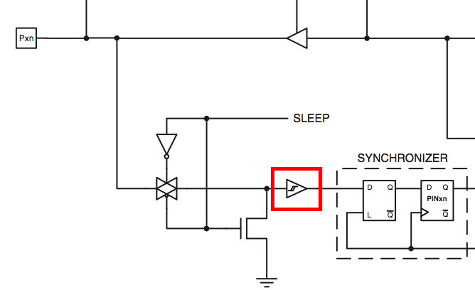
So imagine my delight to find that every ATmega8/168 input pin has Schmitt-triggering. Any pin would do! But I had two particular ones in mind . . .
External Interrupts
All I wanted the program to do was count how fast the propeller blade went by, activate a relay when it got above a higher speed, and deactivate the relay when it got below a lower speed (hysteresis again, at a different layer of the system). For a program that simple, I could write a loop to watch the input pin in software . . . but why, when the ATmega can do it in hardware?
The ATmega pins that are brought out to Arduino digital pins 2 and 3 are “external interrupt” pins. The chip has special hardware to watch for the pins to change state and (if so configured) call a user-supplied routine each time. These calls interrupt normal program execution (hence the name) and then return transparently to the main program when they finish. The Arduino AttachInterrupt(interrupt, function, mode) function configures which pin(s) to watch, which types of changes (LOW→HIGH, HIGH→LOW, or both) to watch for, and what routine to call when a change is detected.
So my program is exceedingly simple. The interrupt handler increments the value in a variable, to count how many times the propellor has entered and exited the beam. The main loop delays for a second (being interrupted some number of times as the propeller spins), then checks and prints the value in the counter variable, and clears it for the next second’s count. In a completed version (more on that shortly), it would compare the current count to threshold values and turn on or off a digital pin to drive a relay wired to the thermostat’s cooling mode control.
/******************************************************************************
 *  fan_timer
 *  Keith Neufeld
 *  June 1, 2008
 *
 *  Count pulses per second of a fan interrupting an LED beam.
 *
 *  Fan wired to digital port 2 aka external interrupt 0.
 *
 ******************************************************************************/

volatile static long counter = 0;

void setup() {
  Serial.begin(9600);

  attachInterrupt(0, count, CHANGE);
}

void loop() {
  delay(1000);
  Serial.println(counter);
  counter = 0;
}

void count() {
  ++ counter;
}
Note that although I requested an interrupt on every change of the input pin’s state, I could (for this project) just as well have counted LOW→HIGH or HIGH→LOW transitions, scaling my threshold values by a factor of 1/2.
How Well Does It Work?
I had never used a CdS photocell in a fast-triggering application before, so I was curious whether it would have a fast enough response to be triggered by the propeller spinning at full speed, or whether the pulses would all mush together. It turns out that it’s plenty fast to watch the propeller — even with the propeller stationary, I was picking up 240 counts per second, from my overhead compact fluorescent lamps. (I’m not sure whether it was getting 240Hz from one bulb or 60Hz each from four bulbs out of phase.) I turned off the overhead lights and it settled down to telling me what the propeller was really doing.
After that, it worked very well. I set it in front of a vent and got 50-60 counts per second (÷ 2 counts/blade [entering and exiting the path] ÷ two blades per propeller ≈ 12-15 rps) when there was no icing and full airflow, and 20-25 counts per second (~5-12 rps) when the airflow was constricted enough that I was ready to turn off the AC and let the ice melt. That’s enough variation that it should be easy to get it to run the AC for a while, then melt for a while.
Installing It . . . Or Not
I had planned to put it in front of the living room vent near the thermostat where it’d be easy to wire in. But then I realized I had just made a shiny spinny cat toy and I was planning to put it in the living room and expecting it to operate unmolested for a week. Ha ha. Ha.
When our house was retrofitted for central air (before I bought it), the old ductwork was upgraded and a master return air grate was put in the floor at the bottom of the upstairs . . . stairs. It’s right around the corner from the thermostat, so it’s almost as close as the living room vent, and much safer from feline interference. The new plan was to set the sensor inside the ductwork and run power and relay wires down through the grate.
And then . . . I started thinking about how more airflow helps keep the AC coils from icing, and there’s this big grate for the return air, and I need to increase the airflow, and I have a box fan, and there’s this big grate, and I need to increase the airflow, and I have a fan, and there’s a grate, and why put a little propeller inside it to measure airflow when I could put a big propeller on top of it to increase airflow.
I laid down the fan blowing into the return air system, and the additional airflow almost completely kept the coils from icing up until my service call Wednesday afternoon, when I got 3.3 pounds of freon added to my 5.4 pound system.
My new heating and cooling company of choice is coming back next week to fix the leak created for me by my old heating and cooling company when they replaced the condensor (outside unit) two years ago, which (the leak) has cost us 2-3 pounds of freon a year. Yes, I should probably press for warranty service on workmanship, but it is so worth the money to get away from them and not have to think about them any more.
So I no longer needed the sensor I had just built.
But That Doesn’t Mean I’ve Forgotten About the Anemometer
For years, I’ve dreamed of building my own IP-attached thermostat. I mean, c’mon, who hasn’t?
Commercially, I can find a good range of options from Proliphix. They look very easy to use and easy to install, and they start at $250 for a basic model. As a network administrator by trade, I give them a huge thumbs-up for this sentence:
The NT10e and NT20e Network Thermostats ship directly from the factory enabled to perform as a Dynamic Host Configuration Protocol (DHCP) client.
With about 10,000 devices on the LAN at work, it’s a nightmare keeping a manual list of all the heating, cooling, and security devices that don’t do DHCP, HP Laserjet 3600 printers that get an IP from DHCP and keep it permanently without ever renewing the lease, Crestron classroom media controllers that work fine for months and then stop renewing their leases, Axis network cameras that get an initial address assignment via broadcast discover but then can’t talk to the subnet’s gateway if the netmask falls on a non-octet boundary which them makes them unable to renew, etc., etc., and keeping a list of the point of contact for every single such device so we can call someone whenever we make network changes that impact netmask or gateway, so they can bring the vendor back out to manually reconfigure the device.
- Whew, got onto a little bit of a rant there. -
Anyway, kudos to Proliphix for preferring DHCP right out of the box. Makes me want to go buy one just to show them my gratitude. BUT the configuration guide doesn’t say anything about SNMP; and if I’m going to go to the trouble of installing an IP thermostat, I’m darn well going to run MRTG or RRDtool to graph my HVAC performance. I want to login to my home web server and see not only the set point and current temperature, but also graphs showing performance over the past day, week, month, and year.
At a bare minimum, I’d expect to graph the thermostat set point, indoor temperature, and minutes of heating or cooling per hour. If I’m going to build my own, I’d throw a couple of sensors outside the house and log and graph the outdoor temperature on the sunny and shady sides as well. Arduino ethernet interface from Adafruit; Fahrenheit temperature sensor from National. This is totally doable.
And I’d really like to be able to graph airflow, to watch visually (and send alerts based on empirical evidence rather than simply a count of days of use) when the air filter needs to be changed. Hence right back to the notion of sticking an anemometer into the ductwork.
Only for the “real” one, I think I’ll use a better propeller not made out of foil, and either an optointerruptor from a dead mouse or a motor and bearing from a dead hard drive.
Very nice. I have been wondering about a decent method for measuring airflow and this was quite the efficient hack… when I implement my HVAC monitoring I may go for something just like this. But here’s another question I was pondering – if you know fan RPM (taking as average value) and integrate over duct cross section can you calculate airflow in CFM? Oh and, you may be interested in 1-wire sensor bus for the HVAC monitoring/IP thermostat, it’s an excellent solution and cheap to implement as well: http://www.digitemp.com/
Here are a couple graphing resources for the Proliphix thermostats… They do not have a “true” SNMP access, but all parameters can be get/set using SNMP like http get requests…
Their API is here:
http://proliphix.com/files/PDP_API_R1_11.pdf
Someone has already created a script to do rrd graphing:
http://www.anders.com/cms/209/IP.Thermostat/Graph/Proliphix
And for a small yearly fee, these people will graph the data for you…
http://inthrma.com
Geoff
Geoff, thanks for the pointers! I’d still love to build my own thermostat, but this definitely addresses my bare minimum requirements for a thermostat and makes the Proliphix potentially viable for me.