As mentioned previously, I was contacted this spring by Amanda McClellan of Coordinate It about an LED design project. Amanda is a civil engineer turned wedding planner and needs about a hundred lighted paper lanterns for a large reception on Labor Day weekend.
There don’t seem to be (m)any LED lighting solutions for paper lanterns, and Amanda was interested in the lower power consumption of LEDs without having to go around to each lantern to e.g. hook up LED throwies. She also indicated a willingness to advise me on packaging the system/solution to sell to other event planners out there, which sounds pretty good to me.
Between distractions, I’ve been working on a design for her. The prototype looks okay, and I think it’s about ready to send out to have boards manufactured.
Specifications
- Make LED drivers to power 10 lanterns with 2-3 white or warm white LEDs each, with some combination of parallel-series wiring.
- Cost should be not more than $2.50 per lantern, or possibly somewhat more if the system is completely reusable.
- Use constant-current drive, for the initial application in the 20mA range but ideally expandable to as high as 100mA.
- Ideally make the string(s) dimmable through optional analog and/or PWM input — but full-brightness when no dimming input is present.
- For Amanda’s use, pack 100 lanterns’ worth of drivers into a monolithic case for the sake of aesthetics and convenience.
- If easily done, make the same driver boards fit into fob-sized cases for smaller applications — Jeremy’s basement, interior lighting for CNC plastic-extrusion machines, etc.
- LEDs supplied separately. I don’t want to be in the business of soldering and testing LED strings that are going to get used by other people. It’s up to the customer to determine and meet their own LED requirements.
- If possible, run from 48VDC source, as I have several hundred 48VDC .38A power supplies I’d love to get rid of for the right price.
Driver Selection
I looked over a lot of LED string drivers before making my selection. Here are some drivers I considered and application notes I looked through:
- STCS1
- 40V max input
- no samples
- Maxim application note on high-brightness LED driver selection
- MAX16805/6 high-current linear drivers
- 5-40V input / 39V LED drive
- 35 – 350mA capacity
- I2C and analog dimming
- single string drive
- MAX16819/20 step-down drivers
- inductive step-down
- requires external inductors and MOSFET
- single string
- MAX16822A/B step-down drivers
- inductive step-down
- requires external inductors
- 6.5 – 65V input
- single string
- Maxim MAX16823 3-channel linear driver
- 5.5-40V supply
- 70mA/channel capacity
- per-channel PWM dimming
- 3-channel
- linear
- ultra-low external component requirement
- National press release
- LM3502 and LM3503 step-up converters
- inductive boost converters
- require external inductor
- 2.5 – 5.5V input
- single string
Given that Amanda wants 100 lanterns with 2 or 3 LEDs each, the 3-channel MAX16823 really leaped out at me. Even though some of the other drivers could support higher drive voltages hence more LEDs per string, the 16823′s three strings trump the higher voltages in the “power more LEDs per driver” category, hence providing a lower overall cost to drive large numbers of LEDs.
Because so many of the drivers have a maximum input of 40V, I gave up on using my 48V power supplies and looked for power supplies in the 24-36V range. I’m having a hard time finding power supplies in that voltage range whose price I consider reasonable, and it’s much worse for anything other than 24V, so it looks like that’s what it’ll be. I’d welcome suggestions on sources for inexpensive 24-40V ~1A power supplies, if you know of any.
With a white LED forward voltage drop at 3.4-3.6V and the MAX16823′s dropout voltage of .3-.7V, a 24V power supply could comfortably run 6 LEDs per string or 18 LEDs per driver. With 2 LEDs per lantern, that’s 9 lanterns; with 3 per lantern, it’s 6 lanterns per driver. It’d be nice to have an even 10 lanterns per driver, but I can live with this.
One nice thing about the MAX16823′s circuit is that it doesn’t require a fixed supply voltage or number of LEDs. Just leave a little headroom between your LED string series forward voltage and your supply voltage and you’re good to go. This means I can set it up for Amanda on 24V with 6 white LEDs per string, but Jeremy could use 12V with 3 LEDs per string, and someone with a 40V source wanting to power red LEDs at ~2V each could connect about 20 LEDs per string. That indifference to the details — as long as you don’t make the linear current controller sink way too much current — is really handy.
Circuit Design
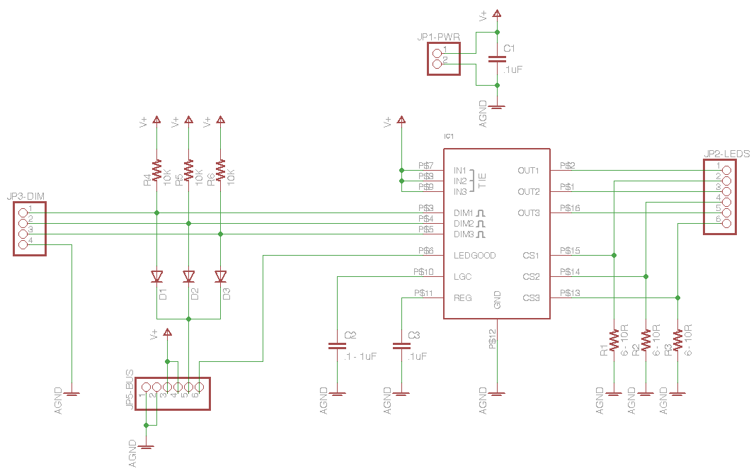
The schematic is pretty straightforward — some decoupling capacitors, current-sense resistors for the LED strings, and inputs for PWM dimming. Because I’d like the same board to work in a fob or plugged into a backplane in a larger case, I included dual power supply and PWM dimming inputs.
I figure if you have a large case of these (at least one I make), you’re more likely to want to dim all of the LEDs at the same time than to dim individual strings, so I used resistor-diode logic to tie the three dimming inputs together to a single dimming input pin on the backplane connector.
I also ran the “LEDGOOD” indicator output to the backplane, to invert and provide “LEDBAD” indicators on the monolithic case to show which strings are disconnected or having trouble. Having discussed it extensively with Jeremy (my first fob presale), I didn’t bother to provide LEDGOOD/LEDBAD indication on the board itself for the fob version — if you’re using the fob to power one to three strings, you can just look to see whether the LED strings are working or not.
Circuit Board
After laying out the circuit board, I tried my usual iron-on toner transfer to set up PCB etch resist, but I had much worse luck than usual and gave up. Tom McGuire graciously agreed to mill me a couple of boards at work and even provided pictures of their awesome commercial PCB mill doing its thing.
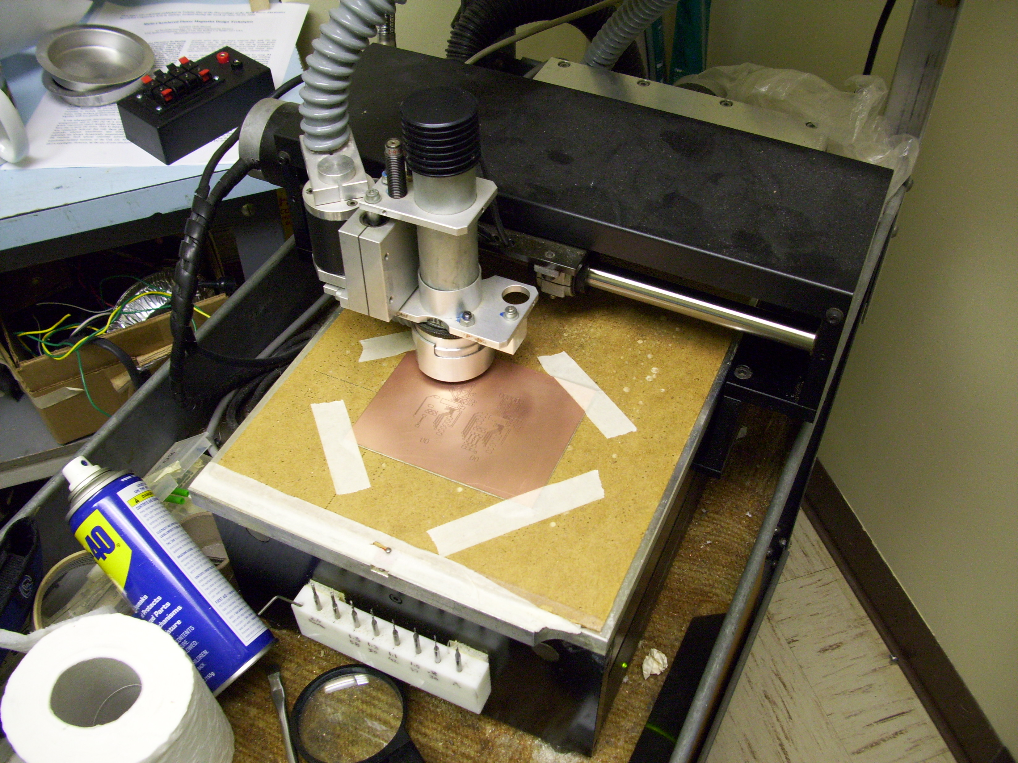
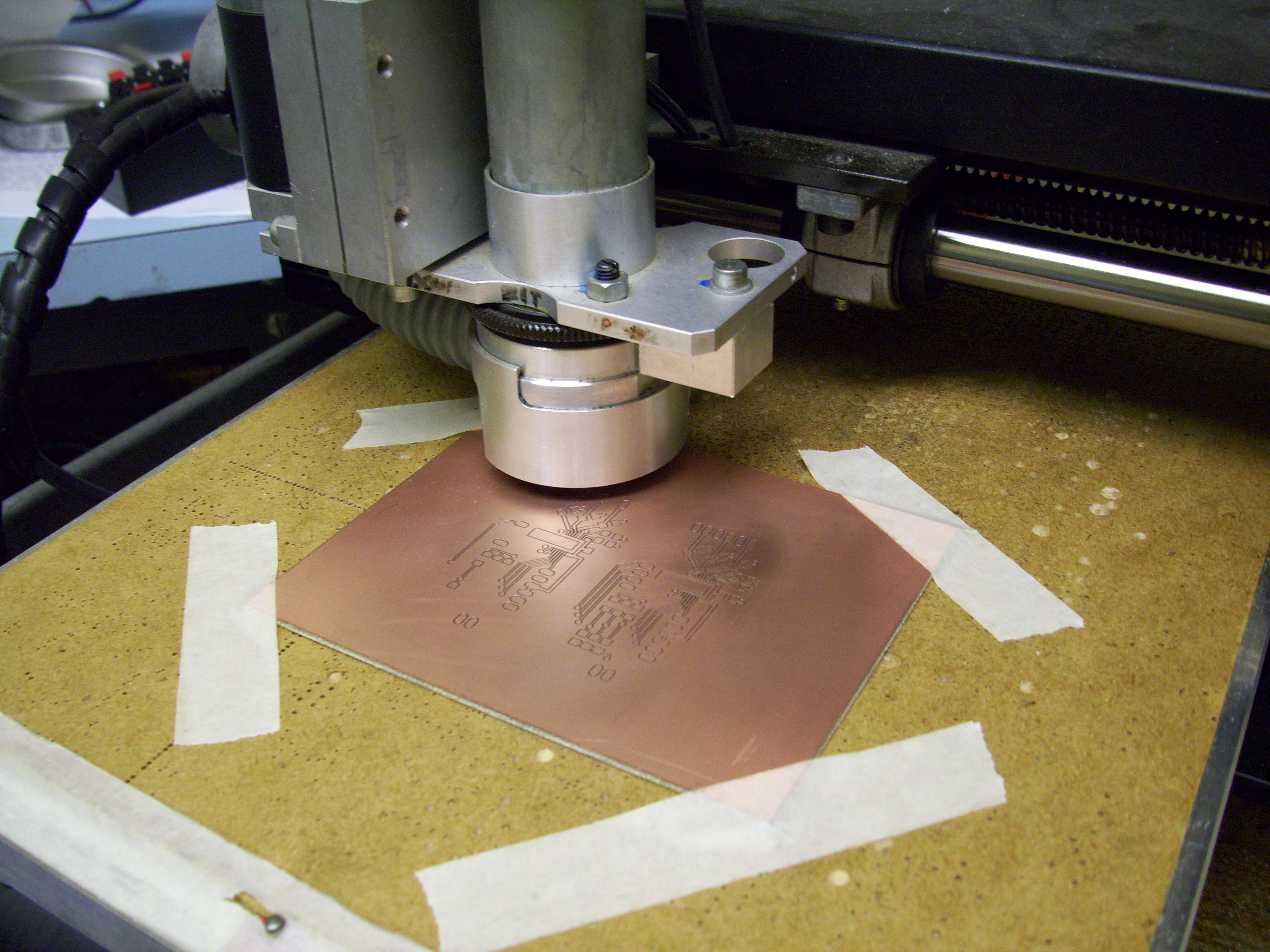
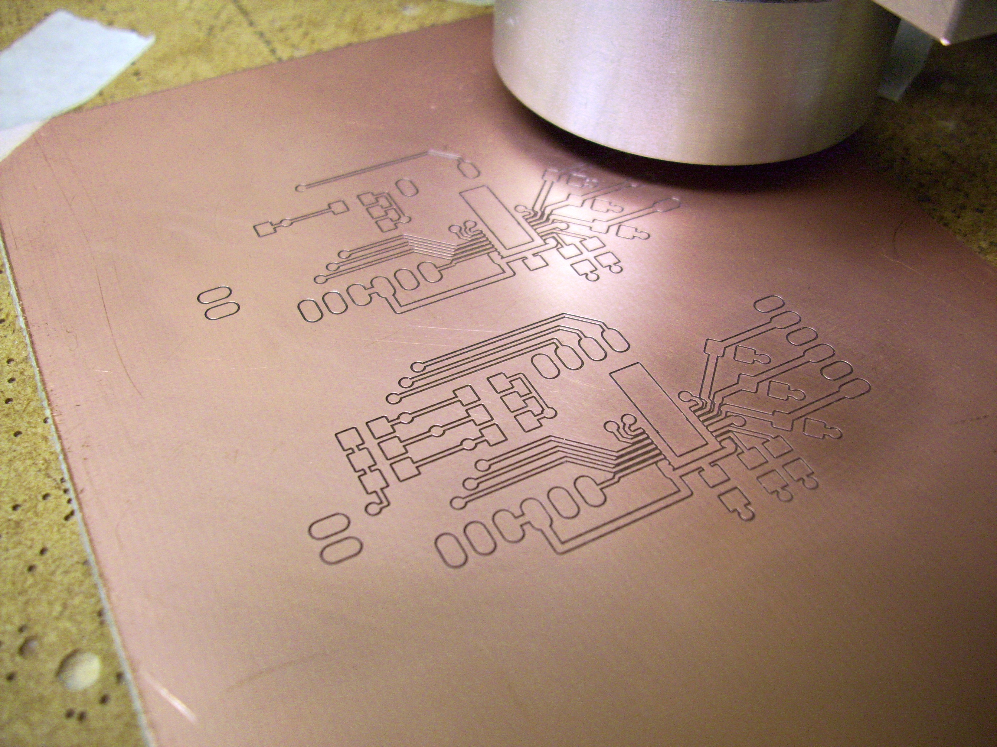
Here are my sad iron-on attempts shown next to Tom’s awesome milled boards.
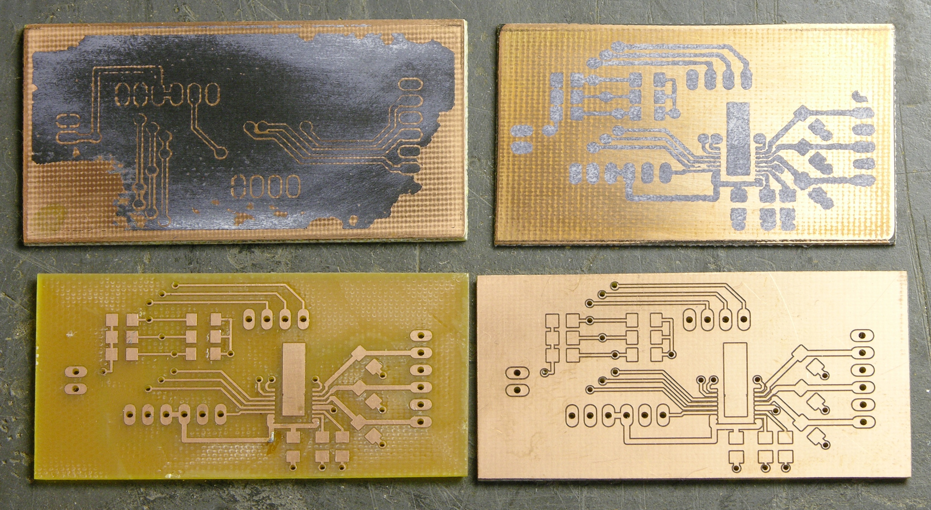
Tom “peeled” the waste copper from the top side of one of the boards, because he’s CRAZY.
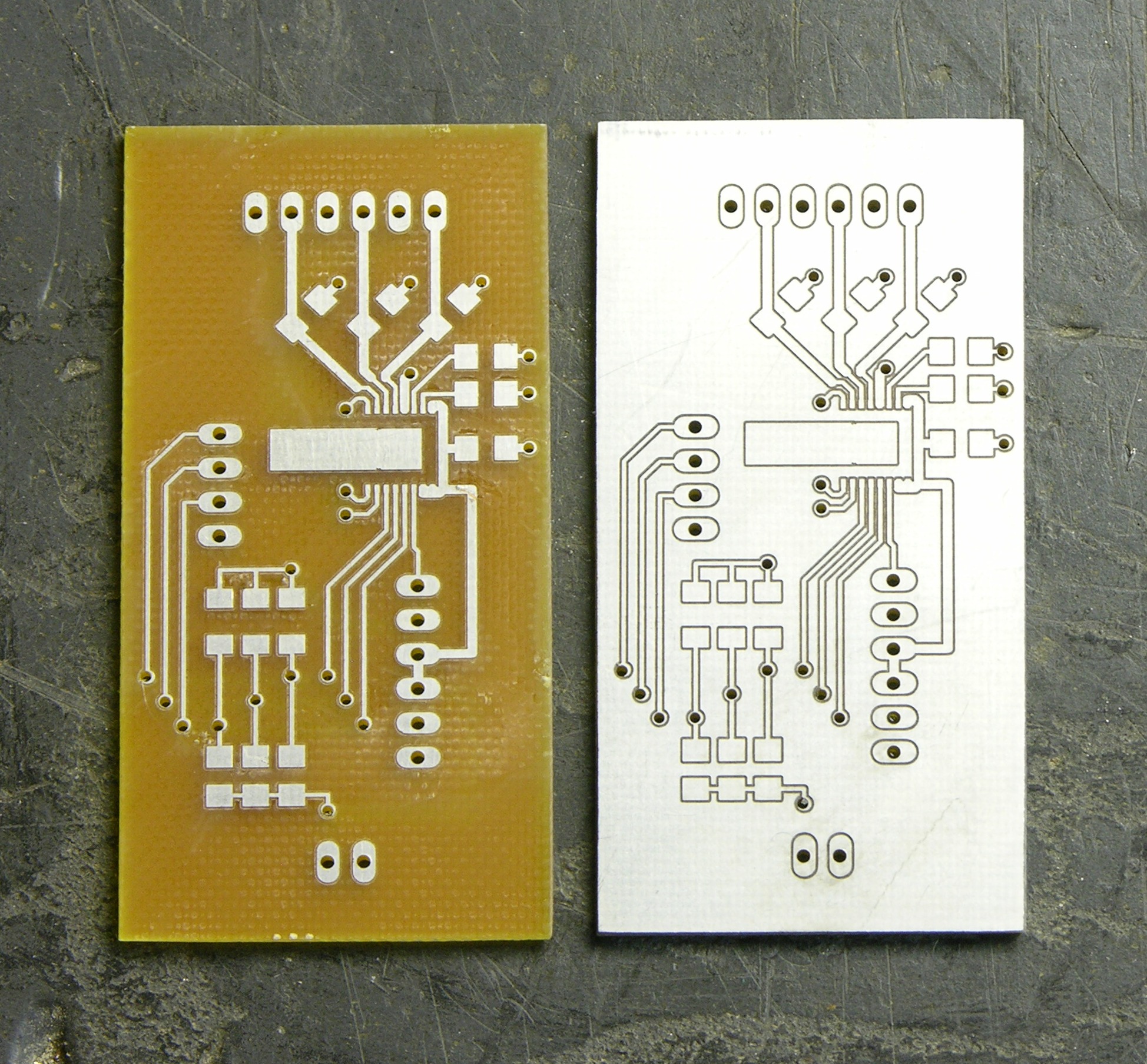
With Tinnit, verra nice.
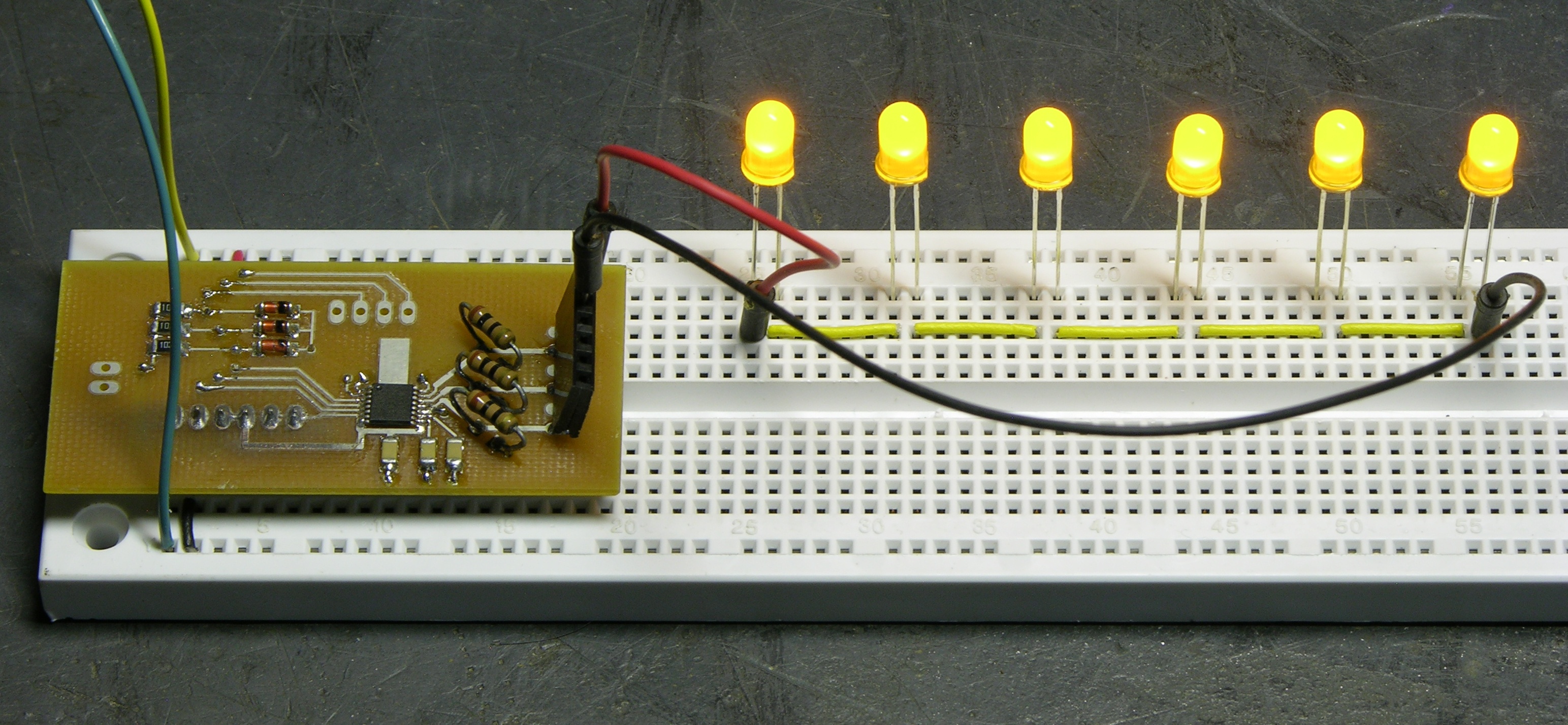
Completed Prototype
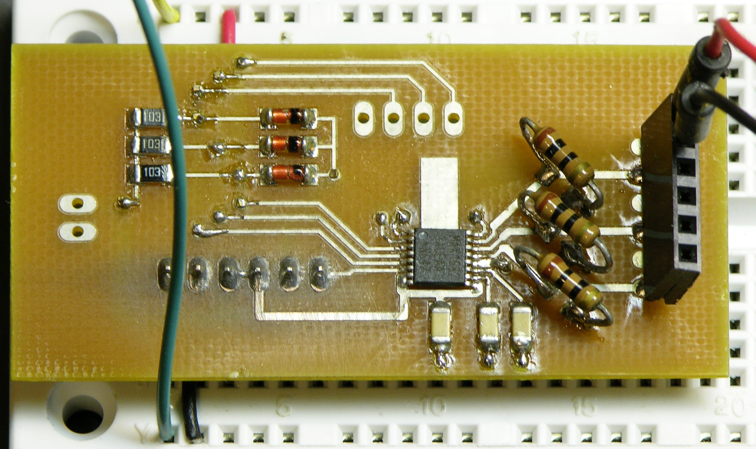
I assembled this a while back and actually don’t remember for sure whether I used the hotplate or hand-soldered and used braid to soak up solder bridges. Given the lack of waste flux around the driver IC, I think I did it on the hotplate.
I intend to use standard 1206 (or smaller) SMT diodes; but these cute round SMT diodes were on hand (salvaged from something) and they fit well enough. Sadly, I couldn’t find any .203V sense voltage / 20mA target current ≈ 10Ω current-sense SMT resistors in my bin; so as you can see, I improvised.
For now, I’ve populated only the connectors I need to test the prototype, and not even with the type of connectors to be used in the production versions. I bodged this together to work on a breadboard; but the real thing will have right-angle male headers for all the connectors.
The LEDs stay exactly the same brightness with a supply of 12-19V (as high as my slightly broken bench power supply will go),
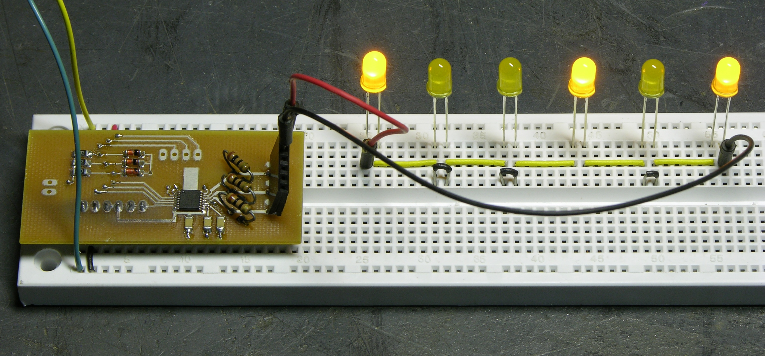
and also stay the same brightness with several of the LEDs shorted out to simulate a string of fewer LEDs. Looks like pretty good current regulation to me.
Next Steps
Right now I need to get boards built quickly for Amanda, so I’ll probably order a batch of 20 boards (enough for 120 or 180 lanterns) just like this, plus silkscreen labels for the connectors. But for the fob version, I want to include a power switch; so I already know there’ll be revisions coming.
I think when the time comes, I’ll print the fob cases using my CupCake.
Availability
I’d like to sell these to anyone who wants them, and I think they’re going to come to $20-25 each by the time I have the PCB, driver, passives, and connectors. (That feels like a lot to me; but in batches of 100, I think that’s about what it’s going to be.) I’m by no means ready to take orders, but I’d take a straw poll. If you think you might be interested, drop me a comment indicating
- likely quantity
- PC board only, fob version, or case with lots of boards
- configured for 20mA drive, something else, or you want to supply your own current-sense resistor
- or “$20-25 is just way too darn much for an LED string driver”
I promise I won’t hold you to it, unless you give me answer #4. ![]()
I’m no wedding planner but I’d like a couple of these for my patio. I’m always willing to assist anyone being innovative. Nice work!
Hey Keith, keep up the nice work! I’m looking to build something like a “starry sky” using a board, lots of fiberoptic strings and a few LEDs each lighting up a bunch of strings. So I’m guessing I could probably use something like this.
Problem is that I hardly know anything about electronics (doesn’t keep me from trying though =P). For instance; would I be able to run that thing using a 9V battery (or several)? If so, I would certainly buy enough to make that project a reality, probably three or four of them.
Magnus, 9V batteries have a pretty low capacity for current/duration. A couple of 9Vs could light (three) strings of five LEDs with one of these — but if you’re running the LEDs at 20mA (I’m doing the calculations on the fly; bear with me) that’d be 60mA for the three strings on one driver.
The rechargeable “9V” batteries I have (which actually only produce 7.2V, so you’d probably want three at a time for strings of six LEDs) are rated for 160mAh, meaning 160mA for an hour, or 1mA for 160 hours, etc. That gives you 160mAh / 60mA ≈ 2 hours 40 minutes — realistically 2 hours — runtime before you have to recharge.
In constrast, a cheap 12V power supply would only let you do three LEDs per string, but would run forever. Alternatively, rechargeable AA cells are available in the 2500-3000mAh range, which would give you 40+ hours of continuous operation before recharging; you’d just need to stack a lot (ten to fifteen) of them to get enough voltage to put as many LEDs per strings as you might like.
I can certainly help you explore power options when I (and you) get a little closer to ready. I’ll also throw out that I’m very interested in building another driver module from the LM3502/3 (or something like it), to use three alkaline or four rechargeable AA cells to power a white LED string. If you want to wait, that might serve you even better.
Thanks for the feedback!
Sounds like I’d go for the AA-alternative in that case since I won’t have access to mains where I plan to put it. The other driver module sounds like what I’m after in that case. There’s no hurry on my end, this just seemed like a good fit for one of my many back burner projects =)
Really inspirational blog btw, good mix of down to earth projects that even I might try and “wtf, you can _do_ that?!” stuff.
Magnus, thanks for the kind words!
I really enjoy being around people who do things that aren’t supposed to be possible to do yourself or outside of a factory. My old friend Sharon once made marshmallow from scratch (reread that if it slipped past you) to see if she could do it. Lawrence heats his in-town house with a wood-burning furnace (not fireplace) and cools it with a water-chilled air conditioner using well water on its way out to irrigate the garden and lawn. His wife Gail has peeled enough grapes to make a peeled-grape pie and spins and dyes yarn to weave. Jeremy is learning op-amp circuits and microcontroller programming to make a color organ for the interior of his car, and slowly realizing that when he needs a “direct box” to capture his guitar amp output into his computer’s audio input, he can design and build one himself with the knowledge he’s already developed. Joel is nearing completion of an on-again/off-again project to make a plastic injection machine from scratch to mold parts for various medieval-related hobbies. It’s great seeing people challenge the conventional wisdom of what you have to buy or leave to the experts or the large manufacturers or someone else and what you can do yourself!
I’d likely buy a board (stuffed, please) just to have a ready way to experiment with LEDs. I haven’t read the spec sheet; is it easy to change the current sense resistors (or perhaps even put a pot in) to get different current drives? Can you set the various channels to different drive levels? That’d make for a great LED test bench.
I usually use TDK-Lambda for my inexpensive switching AC-DC power supply needs. The ZPSA20-24 (open frame) will give you 24V at 0.9A for $23 from Digi-Key. Thanks for the great electronics articles, I hope this helps!
Sean, I think that’s the very power supply I’m currently planning to use. Sure you don’t know of something in the $10-15 range???
Thanks for the note!
Looks like the cheapest I could find on second look is the LS25-24, 24V @ 1.1A for $16.50 from Digi-Key. Best of luck!
Very interesting! I’ve got a question, though: I’m currently toying with the idea of creating an art installation consisting of a display in which each pixel is paper disc with an embedded magnet, which can rotate around one axis running through its center (along its diameter dimension, in other words). The pixels would be flipped by running current through an electromagnetic coil in one direction or another.
This puts me in need of a constant current source, which is unfortunately something I don’t know much about. Do you have a sense of whether the LED driver ICs you profiled would handle an inductive load like this application, or is that asking for trouble? Any thoughts you might have would be very welcome. My guess is that this may unfortunately turn out to be a cost-prohibitive project for the scale I’m envisioning.
Tom, I’m not convinced you need a constant-current source, and maybe you could say more about why you suggested that.
I think the exact current through the electromagnets isn’t going to be that sensitive, and they’ll do fine with a voltage source or (if absolutely necessary) a series resistor. The first thing that comes to my mind is setting up rows with open-collector NPNs and columns with open-collector PNPs and drive the matrix with big port expanders like the PCA9535 I’ve used before. You don’t even need to “strobe” the whole matrix continually — you really just need to hit pixels that are changing, and maybe refresh the whole thing occasionally in case of wind.
In any case, this LED driver is pretty certainly not suited for your needs. But I’d be happy to help you explore more options if you want.
Thanks for the response! My thinking on this is largely formed by my abortive efforts at an LED matrix similar to what you’re describing: a bunch of shift registers running a bunch of transistors (but in this case with plenty of strobing). I wasn’t satisfied with the results — the current draw seemed to be too large for the switching transistors (they got disturbingly hot), leading me to abandon the project. It also seemed likely to generate a tremendous amount of waste heat, which I wasn’t enthusiastic about. I’ve been eager to explore non-resistive means of controlling power consumption, but honestly haven’t got enough of a background to know where to start — I’m a CS guy who’s wandered into electronics through the microcontroller door.
One complicating factor is the three-state nature of the display — at least as I’ve envisioned it. I believe that when each pixel is not energized, the magnet’s slightly unbalanced position — which is necessary to make space for the axle — will cause the pixel disc to rotate to a half on/half off state (admittedly, this may be overestimating the tiny magnet’s mass and underestimating the axle’s friction — I’m still assembling parts for the prototype). This is actually desirable from my perspective, as it gets me an extra .5 bits of color depth if I choose an appropriate background color. But it means that the coils can’t just be pulsed when their state changes — they need to be on, off or reversed in a steady manner. Advice on how to accomplish this would be very welcome!
The art fair at which I hope to install the piece makes a 4′x8′ section of plywood the desired form factor. At 3″ per pixel with appropriate spacing, that’s 512 pixels. The spacing means that heat dissipation can be dealt with, but I’d prefer to draw as little juice as possible. And of course cost is an issue: I’ve been working under the assumption that I will probably need to print and assemble a very small PCB for each pixel (soldering party, here I come). Naturally, I would be delighted to be told I’m wrong about this.
Thanks very much for your advice so far, and for maintaining this blog. I entered an electronics piece into the last edition of the aforementioned art fair in part thanks to the inspiration that it provides — it was especially cool to read about your collaboration with Ms. Rundstrom.
Tom, believe me, it’s very possible to control LEDs with transistor rows and columns — although it requires appropriate selection of transistors, base resistors, and LED current-limiting resistors. For individual low-power LEDs, constant-current control is overkill and resistors are fine. This driver is intended more for powering longer strings of LEDs where slight manufacturing differences are magnified by the number of LEDs in a string and slight power variations would be exacerbated by the relatively small voltage drop across a resistor.
That’s a tangent, though. Back to your display.
I was definitely picturing a display with spring-loaded two-state pixels that would return to the other state when deenergized. Keeping the magnets on constantly is going to be a lot trickier, and reversing the current to the magnets is also going to be tricky on this scale. A 16×32 matrix with only one row or column active at a time, and unidirectional electromagnets, feels pretty doable. I’d need to step back and rethink whether I can see any affordable way to do tri-state electromagnets.
I’m fascinated by your reference to an electronics piece you entered in the fair already — do you have it documented online, and/or could you say more about it?
I must be missing something. You want cheap and you have a bunch of 48 v supplies. Why not go ultra simple:
48v   ____o_o_o_..._o_
               |                      |
               |       R            /
               |_\/\/\/\/\___ | /
                                  |\ Q
                                   v
Gnd ______________|
Sorry for the crude graphics. Q is just an npn power transistor, adjust R for the current you want (or use as a dimmer) and the “o”s are your leds. Q’s collector-emitter voltage should adjust automatically to maintain the current in your leds, up to the maximum number of leds that would add up to a 48v drop (12 – 13 if you aren’t triskaidekaphobic). Obviously, if you don’t have enough leds, Q will be burning power, but it sounds like your mains powered, not battery, so it seems one could sacrifice efficiency.
Oops! The graphic looked a lot better (not good) when I typed it in, but lost something in translation. Hope you catch my drift: just use a bipolar transistor and a resistor as a constant current source: http://www.ecircuitcenter.com/Circuits_Audio_Amp/BJT%20Current_Source/BJT_Current_Source.htm
Keith,
Have you tested your driver using (presumably) long narrow gauge wires, like the kind that will attach one luminary to the next in your application?
I’m thinking you’ll run into trouble with the excessive length and capacitance of the wire messing up your regulation. Most LED driver circuits are designed to be installed right next to the leds they’re driving.
If you’re going to be using a regulated 48v power supply to run this off anyway, why not use linear regulation? Five three led luminaries (fifteen leds) would consume most of that voltage and a simple LM317 based constant current regulator can burn off the rest.
Alternately, looking at your rather low price tag $2.50 per luminary (good quality warm white leds will blow that away), how about building discrete joule-thief drivers for each luminary. They’re dead simple, really small and can be easily packaged as a commodity item, just build them into a AA enclosure modified to hold the circuit and a AAA battery. Plus you can have any many or as few operating as needed.
Charles, sorry about the schematic getting all hacked up; WordPress treats comments as raw HTML by default. I put some <pre> tags around it and it looks better.
I recognize that those won’t be compelling reasons for everyone.
So this is a serious question — why are so many companies making constant-current LED driver ICs, even linear ones (like this), when it’s so easy to do with a few discrete components? What’s the value-add?
Gordon, thanks for the note about long leads. I’ll give it a test — that’s a good thing to check.
The MAX16823 is a linear regulator — just a highly integrated one, with some extra features (PWM dimming). Interestingly enough, I have another project in the works that is using an LM317 as a current limiter.
Regarding the Joule thief and the like, an important feature for the initial application of party lighting was that no one have to go around to each lantern to turn it on/off — that they can be installed in advance and then switched on remotely when it’s time. Amanda had already looked at using LED throwies and specifically rejected that class of ideas. Additionally, I think there’s more interest for this circuit for LED strings other than party lanterns, where the throwie / Joule thief model doesn’t work well.
For what it’s worth, the warm white LEDs that Amanda liked cost me $.25 each, two per lantern. You may not feel that they’re good quality, and they’re certainly not bright enough for illumination (she specifically said accent lighting, not illumination), but they’re what the customer wants.
Sorry for the delay in responding, Keith — I have some video that explains the project, but haven’t yet found a chance to edit and transcode it. I’ll add a comment when I do. I appreciate the interest!
<>
…because leds are not _always_ used for aesthetic purposes only… a precise current source is required anytime you have to use your leds to measure something like a distance in an industrial equipment, each time you need to run your lamp forever and want to avoid damages/power leaks… think of the precision required in a scanner or a led-printer…think of the led backlighting in modern laptops… if you have not such requirements i think wiring some leds to a (variable) resistor and a battery is just fine (and you’ll save 20$). Anyway: i liked the article because it shows a professional way to do things. Keep going, Keith!
I found your site linked via Makezine.com. I’m currently looking at installing some LED lighting on my motorcycle as accent lighting around the underside of the gas tank and around the engine. Commercially produced LED setups are ridiculously expensive, upwards of $80-100 for what I want. So I am considering doing it myself.
My supply voltage is 12v DC from the bike. I’d like to drive as many LEDs as possible off that voltage, and have them as bright as possible while maintaining a safe operating voltage so as not to let out the magic blue smoke. I’d likely be making a couple strings of 10-12 ultra bright yellow LEDs for each side of the tank, and a couple other 2-3 LED strips for added lighting elsewhere.
Any suggestions on how to approach this using a constant power supply like this? I’m a bit of a noob as far as electronics, but I can find out the power draw for the LEDs. I’d need to know how to configure the chip to supply what I need.
Love the article, and everybody’s comments. Looking forward to digging through more of your site.
-Thomas
Morgan Hill, California
Thomas, how crucial is it to you that the LED brightness not change when you idle and rev the engine, the way car headlights do if you have the wipers and air conditioner running full blast and you pull to a stop sign? If you can live with some variation, I think you’d be better off with a simple (and cheap!) current-limiting resistor.
You’ll get the least variation in brightness if you dedicate a resistor to each LED, but that takes more resistors and more wiring. I’d experiment with different length strings of LEDs with a resistor per string.
As I recall, the yellow LEDs I’m using have a forward voltage drop of about 2V. That means on a nominal 12V source, you could use five in a string (about 10V) and have a little headroom left over for the resistor. The problem with using so many in series is that the 2V headroom turns into maybe 1V when the battery is drained (high beams on and engine idling) and maybe almost 3V when the battery is fully charged (lights off and engine racing).
I’d suggest scaling back to three or four LEDs per string, giving you 6V or 4V headroom. Assuming 25mA maximum current, that’d call for a 240Ω or 160Ω resistor in each series string. Where you wanted ten to twelve LEDs, just use several strings of three to four positioned close together, with each string’s ends wired back to the battery.
Want to play with that and see how it goes?
If you’re not satisfied with the consistency of the results, we can talk about constant-current drive again. The problem with the driver I’m building is that it’s limited to the voltage of the supply feeding it (12V on your motorcycle); and that because it doesn’t have the resistor in each LED string, you can’t put several strings in parallel the way you can with the “resistored” strings. That would limit you to five LEDs per string times three strings per driver IC for a total of fifteen LEDs per driver.
I’m also working on a second, slightly more complicated driver that uses a voltage-boosting IC. It’ll take an input voltage like your 12V and boost it up to a much higher voltage to run many LEDs in the string — potentially up to 48V for 20+ yellow (or 12+ white) LEDs. That might be enough to get your whole bike from one driver … if you’re not in a hurry and you can wait for it.
Probably the current limiting resistor would be the way to go on this. Fewer parts count, simpler. If the LEDs brightness drops while sitting at a light it’s not critical, purely decorative.
I think I’ll drop by my favorite surplus store on the way home this evening and grab a bag of ultra bright yellows and some resistors to dink around with over the weekend.
Ultimately, I’d like to produce some small stick on boards (and open source the board layout) that can be plugged together in parallel that I can have manufactured for far cheaper than the existing lighting solutions for motorcycles ($80 for 12 LEDs??? C’mon now…). For now, I’d just etch my own. I think I’ve got the idea as far as the schematic, just have to sort the resistor values once I get the LEDs sourced.
Very likely these companies make the same thing, but put it into a nice package and pot the whole thing with epoxy so you can’t see how simple it is, then sell for ridiculous profit. I’m just not paying that.
TLHarrell: if you decided to scale up, check eBay for sourcing LEDs. A lot of LED vendors there sell their wares with matching sets of resistors under the assumption that they’ll be on a 12V rail, precisely because so many people are buying them for automotive applications.
I have had good experiences with this vendor — ships quickly from Hong Kong, and they’re willing to put together custom orders for you:
http://stores.shop.ebay.com/Shop4leds__W0QQ_armrsZ1QQ_fsubZ13016932
Tom and Thomas — just remember that in the included “free” resistors will be surplus items, since they’re provided to set the current for one LED on a 12V supply, and you’ll burn less power in your resistors if you string together a few LEDs with a single series resistor.
On the other hand, this doesn’t really require a high-efficiency solution; and maybe you’d rather go with one resistor per LED.
I forgot to mention earlier — the reason to go with three to four LEDs per string instead of five is that with greater voltage headroom, the variation in supply voltage becomes a smaller fraction of the headroom hence has less impact on LED brightness. You can try different LED counts (each with an appropriate resistor to limit to 20mA) and use whatever behaves the way you want.
Instead of paper for iron-on transfers, try transparency film. Virtually all the toner will transfer, and its easier to line things up because you can see through it.
I would be interested in a couple of the boards. I am looking to power 500mA LEDs so having just one LED per channel would be perfect if it could run the higher current LEDs.
Thanks,
Mike
Mike, unfortunately these will only do 100mA per channel, and you can’t parallel the channels. I’ll probably look down the road at building a switching model for higher-powered LEDs.
JP, I just saw I had never responded to your comment.
The current sense resistors are SMT and soldered onto the board. They’re not something you’d want to change much once they’re soldered in — but I could leave them off and you could attach pots on fly wires. The three channels are indeed independently regulated; and you pick R = .205V / Itarget, so 10Ω for 20mA and more for less or less for more.
Like the motorcycle project, I’ve thought about using some LEDs on my car. So far my LED projects have used the typical constant-voltage source with a current limiting resistor on a series string of LEDs. That automotive voltage variability from 11 to 14 volts has stopped me from going further until I learned more.
I am wondering if a linear voltage regulator would make an easy solution. For example, a 7812 or LM317 in line with the LED string and current limiting resistor. They look pretty cheap; is it worth pursuing?
Got my LEDs (some nice 1watt yellows). After poking around on the net and scratching my head over how this all works as far as calculations, I found a pretty neat little site that will help with calculating the resistors needed for series strings of LEDs. http://led.linear1.org/led.wiz Only thing is it seems to be a tad on the basic side… but good in a pinch.
Seems a little counterintuitive to me, but if I run 5 LEDs in a string instead of 3, the resistors end up dissipating too much current. I currently have 6 total LEDs, one for over each cylinder head on each side, and a couple spots for other locations. I’m a bit of an electronics noob, just have enough knowledge to know that there’s stuff I don’t know which is good because it keeps me from melting too many things down.
Here’s what I have:
(6) American Opto Plus Yellow LED PU-1WLYE (120deg angle)
Power Dissipation: 1.05w Forward Current: 350ma
Peak Fwd Pulse: 500ma Reverse Voltage: 5v
Forward Voltage: 2.4v Max. Voltage: 3.0v
This calculator site shows for a source voltage of 12v, 2.4v to the LEDs @ 350ma, with 3 LEDs in a string, that I need 15 ohms resistor. This resistor would be dissipating 1837.5mW (1.8 watts). Obviously that’s too much for a 1W resistor. Would it be better to put say 3 1W 15 ohm resistors in parallel so they divide the load? Trying to wrap my head around this as it’s been quite a while since I was in High School electronics.
Thanks for your help and insight into this so far. I’m actually starting to sort some of this out again.
Oh, and to make comment to above (Eric)… I’ve used mylar film for toner transfer before. Make sure you set the printer to extremely dark, and print on the shiny side of the mylar. When transferring the toner to the board, place a round dowel under the board (like a see-saw), the transfer on top of the board, iron over that. The dowel makes the board flex slightly improving adhesion dramatically.
Sorry for the delay. Here’s a link to a video of the project that I referred to above:
http://www.manifestdensity.net/2009/08/18/my-artomatic-piece-explained-finally/
TLHarrell: if you parallel up three resistors to make 15 Ω then you’d want them each to be 45 Ω (well, 47 Ω for easily available values). Alternatively, you could put three 5 Ω (again, probably 4.7 Ω) resistors in series and also split the power evenly. If you already got the 15 Ω resistors before realizing the power dissipation was too much you could use four in a series/parallel arrangement.
Tom, very fun project! Thanks for the video!
I’m just getting into electronics, but I would be interested in one of these. You keep refering to fob, can you explain what that means exactly? Thanks.
Matt, like the plastic keychain to unlock your car doors remotely.
Hey Keith, how soon until you start selling these?
Hi Keith,
My LED project advocates a forward current of 200mA for a LED-TECH.DE LT1556 2.5W warm white module and my power supply is taken from the doorbell transformer in the 8 to 16 vAC range.
I would be interested in purchasing your driver if I can confirm suitability?
Thanks for the informative article, clear, concise and a fun read. It helped a lot due to your comments on the trade offs behind part selection.
Best regards
Neil, thanks for your interest!
This driver won’t do more than 70mA. Additionally, once you start getting up to currents as high as you’re proposing, you’ll be much happier with switching regulators; linear regulators would get quite warm. So I don’t think this is a good choice for your project.
I’d suggest for a quick solution, search eBay for “LED driver” and look at the offerings in particular from Sure Electronics. They have some good, inexpensive drivers in the range you’re looking at. They’ll probably require DC input, though. I do see some drivers from other vendors with AC input, but they seem to be mainly line-powered.
Hope this helps!
The PCB milling machine we used to make the boards was an LPKF 91s. You can visit their web site here but the 91s is way old and probobly not suported any more. But it still has a lot of life left in it. Knock on wood. http://www.lpkfusa.com/
Tom,
Thanks for the info on the PCB mill!
You should check out the newer ones. 100K RPM and sounds like a jet engine!!!
Kevin,
If I read the datasheet right, this drive is three *independent* channels. Might be able to be used for 4 pin RGB LED’s to produce full color spectrum (rainbow) with the dimmer features somehow.
How does a constant current source help you if the leds are in parallel? They will all share the main current but could each have a different current through them.
“Joe,” your query fills me with questions in return:
Why do you sign your name “Joe” but provide an email address of ray.<lastname>@<ledvendor>.com?
Why are you Googling for
Leds in parallel "constant current" drive, which is how you found my blog post?Since it was almost exactly five minutes from the time you browsed to my blog until the time you posted your comment, couldn’t you have bothered to read that this driver IC has three independent current-controlled channels and no one is advocating parallel-series operation?
Hi Keith,
I was googling for constant current drivers (the MAX16823 would be ideal if the PWM could run above 3kHz) and came across your blog entry. You talked about the cost of power supplies. Given that you have a constant current driver, do you need a regulated supply? Could you use a cheap 24V transformer, bridge and reservoir capacitor?
HTH
George
George, sure. But (1) I have no desire to build power supplies, and (2) I couldn’t get it UL listed, which (3) scares me to send out into the world for people to plug into AC power.
Keith, First and foremost I found your site looking up projector repairs… Well, several hours later the LED project seems to be something I would like to also add my name to the list of interest.
To echo some other comments, awesome site, great descriptions and I wish I knew half of what you could have discarded as useless knowledge. My interest in electronics is poorly funded in the ole grey matter department.
Keith, I hope that this thread is still alive, because I could use your help.
I am building an DSI (surface illuminated) display for multitouch tracking. I’ve been building an AC circuit using capacitive reactance to drive the ~100 IR leds that need to run the outside of the surface. Each LED has Vf of 1.2v @ 20mA optimal current. I’ve only just realized the value of constant current drivers but was wondering if/how your solution would work for me? Would I need to hook up a whole bunch of small strings or could this drive the whole array?
These LED’s will likely have to be on for a long time so my guess is that battery power is not useful.
Your thoughts are very much appreciated.
Scott
PS – I know that I can buy a strip with prebuilt driver but A. they are expensive and B. I would like to build the tech from the ground up the first time. Thanks Again.
Scott, I don’t know whether you’ve browsed far enough in the blog to see the EasyBright I ended up producing. It supports a supply up to 40V and three LED strings at preconfigured currents. So if you could find a 40V power supply and your LEDs have exactly Vf = 1.2V, you could run 33 LEDs per string for 99 on one EasyBright.
I’d be leery about the 40V supply being regulated well enough to have enough headroom and would feel better about 30 LEDs per string (36V). Or 20 LEDs per string (24V) would give you more flexibility in power supply selection (28-30V laptop supplies are fairly common) and five strings would get you 100 LEDs (six would get you 120) on two EasyBrights.
If you want to put gel cells into your project, two would give you nominal 24V with at least 22V before they’re too discharged to be useful. 16-17 LEDs would be about 20V per string and six strings would cover your 100 LEDs.
Regardless of the supply and the number of LEDs per string, each string only draws the 20mA of the individual LEDs, so you’re looking at 100-120mA for the whole schmear. On a series pair of 7Ah gel cells, that’s at least 5 usable Ah = 5000mAh ~= 50 hours.
I recently collaborated on an art installation containing one used, two-year-old gel cell powering quite a few LEDs, two IR proximity sensors, and a motor. It’d go about 20 hours of light use to 5 hours of intense motor activity before winding down and needing a charge.
Hopefully some of these numbers give you ideas about avenues to pursue?
Hey Keith,
Thanks very much for the speedy reply. I will keep digging around and follow up on your suggestions. Incidentally, I realized that my circuit, using .5 uF Cap on the + and 1K ohm / 250V resistor on the backend to deal with inrush, is basically finished for use on a 120V AC main. I am going to add 2 Zener Diodes rated for 110V to regulate spikes and then I think I am all set. I think that for mobile solutions though, your method may work perfectly and the gel cells are a nice idea. Thanks very much.
Hi, anyone has a simple driver plan for:-
Input DC 4.8v – 5.6v
Led 3 x 3W, working voltage 4-5v each. So had to wire in parellel
Prefered current 0.8A-0.9A
Please email me ngwanhoe@yahoo.com
Thanks a lot