In early February, a correspondent pointed me to Jeff Keyzer’s mightyOhm blog. I immediately ran across his homebrew PID-controlled soldering hotplate and improvements, and immediately knew I had to have one.
I contacted Jeff through his blog and he was great about sharing his knowledge. He’d built his hotplate using the last of some surplus parts he’d picked up at a now-closed store in the Valley and was considering ordering a batch of parts to make a few for all the folks inquiring about them, but hadn’t done so yet. I was eager, decided it’d be quicker to make my own (and three months later, that may actually have been correct), and went off to eBay to find myself some parts. I also bought aluminum and took a practice run at polishing it.
Most of the CupCake PC boards are SMT; and although I’m very comfortable soldering SMT by hand, I really wanted to get my hotplate up and running and use the CupCake boards as a chance to try out reflow soldering. (That’s why I started by assembling the opto endstop boards, which are the only all-through-hole boards in the kit.)
So last night I got a working proof-of concept hotplate going, and tonight I can start on the CupCake SMT boards. W00T!
Here’s the tale of how to build a copycat PID-controlled hotplate, with a digression into how lucky I got buying exactly the right PID controller with no idea what I was doing.
PID Control
PID stands for proportional-integral-derivative, and you can read about it in great detail on Wikipedia, among other places.
To provide a brief recap:
- Many electrical control systems (not just temperature, but any process control) are “bang-bang,” meaning that they turn an actuator all the way on or all the way off — like most residential furnaces.
This is like a male teenager’s approach to driving a car: When you want to accelerate, floor the gas; when you want to slow down, take your foot completely off. [I'm saving the brake for the description of a two-control system later. This is called foreshadowing.] - The P (proportion) term takes into account the magnitude of the difference between the current value and the desired value, and applies a variable control (or a variable-duration pulsing control) to the actuator.
This is how more experienced drivers control speed on level roads: When you’re far below the speed limit, give it a lot more gas; when you’re almost up to the speed limit, give it less. - The I (integral) term takes into account the duration of the difference between the current value and the desired value.
This is another aspect of how experienced drivers control speed: If you find that easing off of the gas as you approach the speed limit has left you a little bit short and you’ve been driving too slowly for a while — or if you’re going uphill and the pedal position you thought was correct for your desired speed just isn’t keeping you going as fast as you want to — give it a little more gas. - The D (derivative) term takes into account the rate of change of the difference between the current value and the desired value.
This is probably the most difficult to grasp intuitively because it feels a lot like what the proportion term already gets you, but consider this: If you’re rapidly accelerating up to the speed limit, back off the gas a little even if you’re not quite there yet. It helps keep you from overshooting the speed and having to slow down.
My Controller
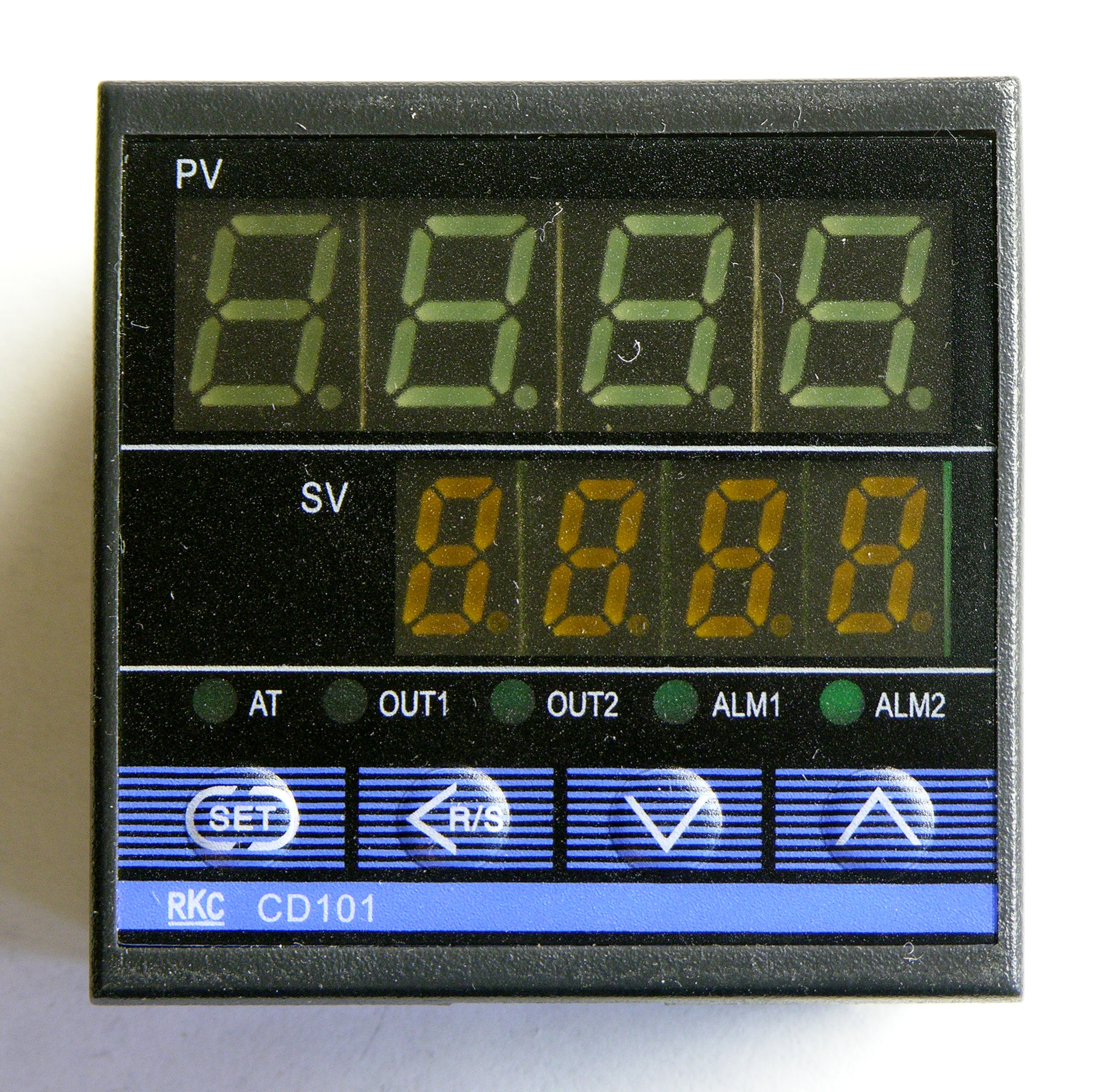
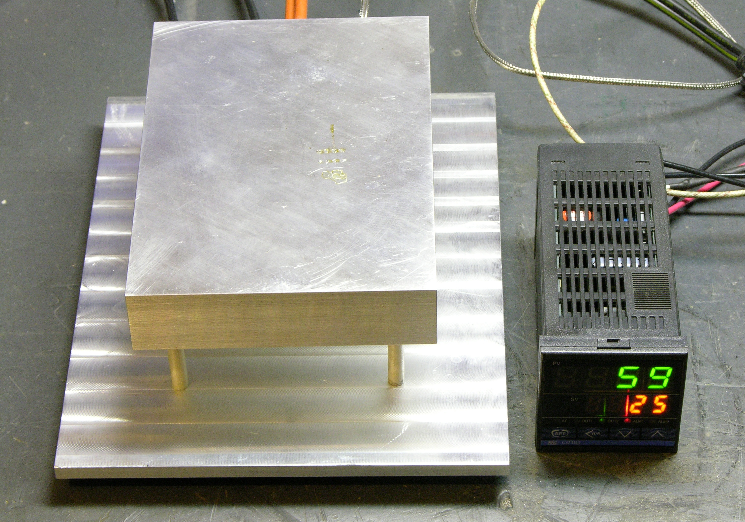
So I bought a PID controller (with thermocouple) and external solid-state relay (SSR) on eBay. The PID controller in the auction looks exactly like Jeff’s; the one that shipped (above) is close but not the same. And the manual is baffling, to someone who hasn’t worked with PID controllers before. The connection diagram didn’t help at first, either; it shows every possible option, not just the one implemented in this hardware.

My PID controller touts two outputs. OUT1 is a voltage pulse, and OUT2 is an internal relay. When I read “voltage pulse,” I feared that it was intended to trigger some external process that would run for a while every time it was triggered; and I had no idea why there was a second output.
Cort and I had connected it and watched the LEDs on the front, and couldn’t figure out what was going on; so I was afraid I’d made a poor selection and was going to have to do some rewiring in order to make it work for me — rewire the voltage pulse as a steady voltage, rewire OUT2′s relay to deliver the control voltage directly to the outputs, provide an external 12VDC power supply to run through the relay to control the solid-state relay, etc.
Not so. Yesterday afternoon I sat down with the controller and the thermocouple and discovered that:
- The thermocouple’s wiring is directional. I hadn’t studied thermocouples before and I first wired it up backwards, and was surprised to see the displayed temperature drop when I warmed the probe.
- The OUT1 indicator flashes while the process (measured) value (PV) is less than the set value (SV) — with longer on-time the further the PV is below the SV. Far enough below the SV, the indicator just stays on.
Ah ha! OUT1 is a pulse-modulated output, and that’s what “voltage pulse” means. It’s exactly the right thing to drive my SSR controlling a heater cartridge — it turns on constantly when it’s a lot too cold and pulses on for briefer and briefer periods when it’s only a little too cold. Perfect!
Setting for Fahrenheit
The controller had been listed as F/C, which I assumed was Fahrenheit/Celsius, but I couldn’t find any mention in the manual of how to set it for Fahrenheit. I emailed the seller and they sent back instructions:
For changed the reading in Fahrenheit, you can hold the
‘SET’ button for more than 3 second to enter setup mode.
Switch the read
to display ‘LCK’ and change the parameter to ’1000′.
Now hold the ‘SET’
and ‘<' two button together for more than 3 second.
The read will display
'Cod'and '0000'.
Switch the read to diplay 'SL 2' and change the parameter
to '0001'. (0000 means in Celsius, 0001 means in Fahrenheit)
Hold the
'SET' button and the temperature reading will be changed in
Fahrenheit.
And the instructions work … sort of. The process (measured) value changes to Fahrenheit, and I think the set value does too. But then the SV only goes up to 400°F instead of to 752°F (400°C, the range of the thermocouple), and that doesn’t seem right. I’ve emailed the seller to ask whether there’s another pertinent configuration item; and meanwhile (even though I don’t need to go that hot) I’ve put the whole thing back to Celsius.
Inside the PID Controller
Oh, you wanna see inside? I couldn’t resist taking it apart.
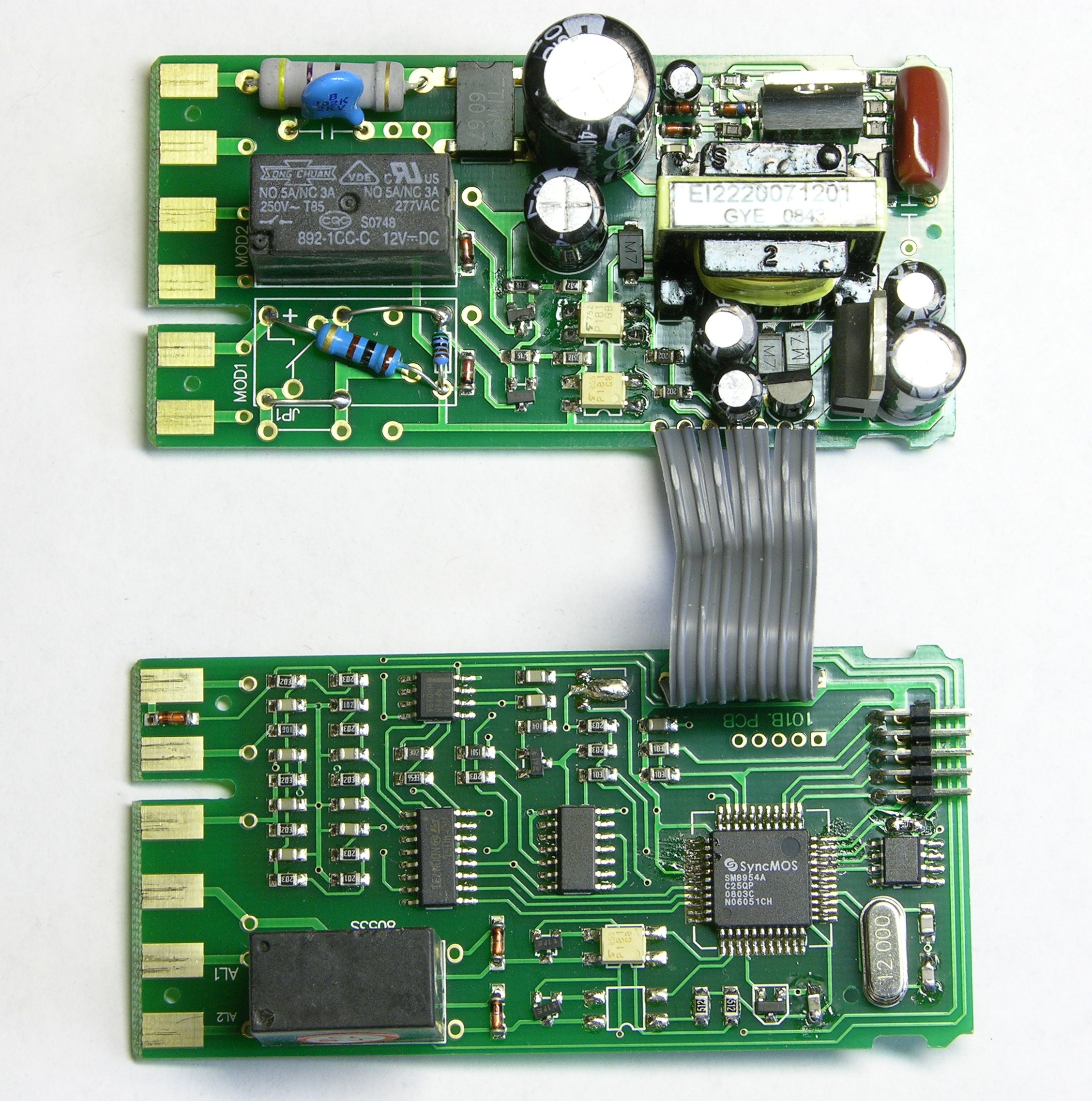
It has two main PCBs. One has an off-line switching power supply and space for two output modules — relays or wiring and resistors for voltage/current drive, depending on the build options. The other has a SyncMOS SM8954A microcontroller that’s the brains of the outfit, and wiring to a relay for an “out of range” alarm.
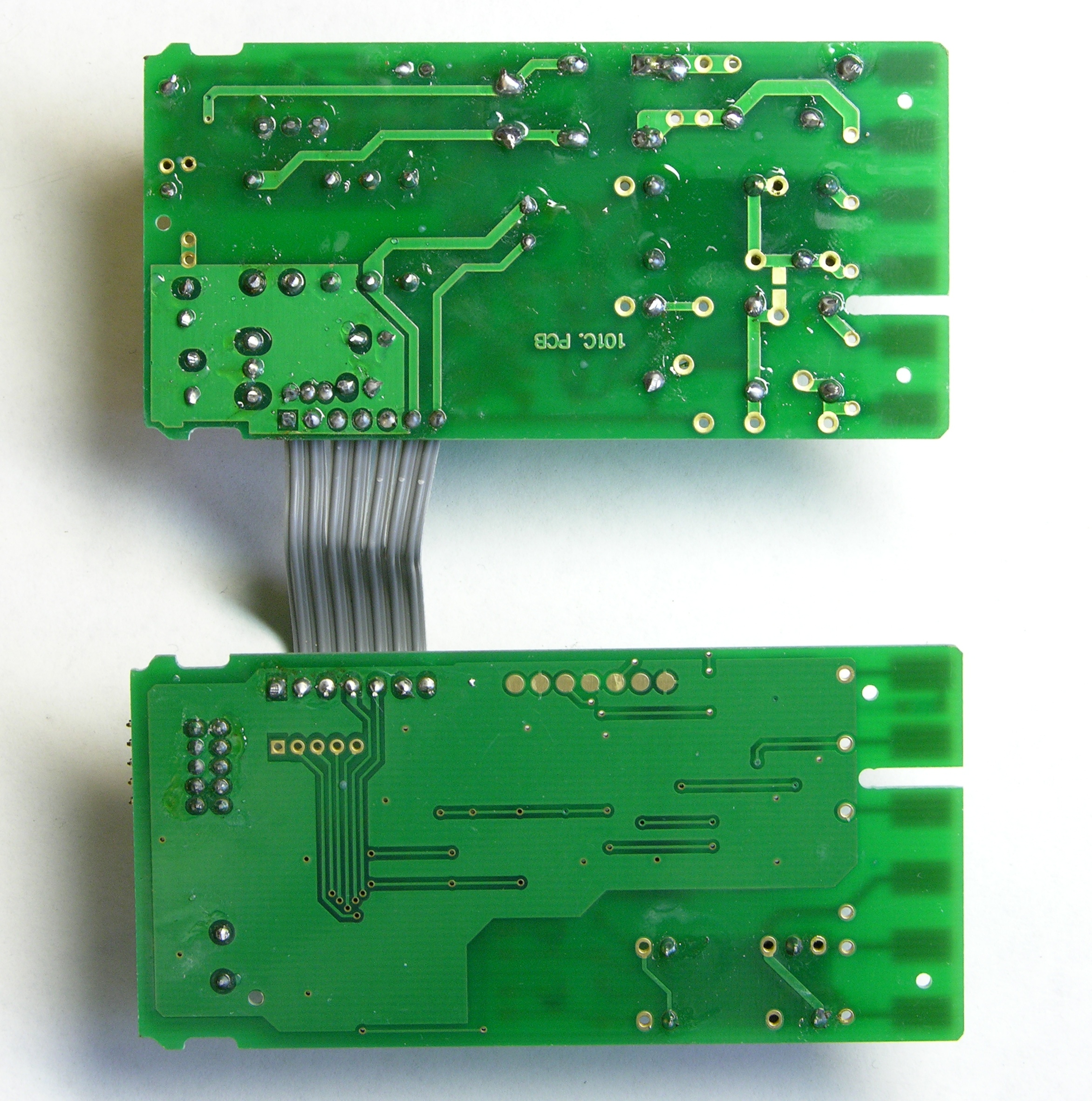
The back sides of the boards are pretty sparse — the most interesting thing there is the traces from the microcontroller to what I assume is the in-system programming header.

The microcontroller board has a header that plugs into the back of the front panel, and the front panel’s plastic surround has locking tabs to hold the two main PCBs in place, parallel to each other, standing up on edge.
Heater Block
I want to polish my heater block, and I had a friend mill it to provide a smooth surface to begin polishing. That’s a subject for another post as soon as I can get back to take some pictures of the massive, commercial CNC milling machine in his shop.
Due to availability of time over the last few weeks, my heater and base plate are milled but not yet polished. I considered what other work needed to be done in order to assemble and test the hotplate and decided that everything was dismantleable — I could go ahead and get it set up, then come back and polish later.
Cartridge Heater
I had bought a 5″ long, 3/8″ diameter heating cartridge on eBay. Jeff used a 500W heater and said he didn’t need quite that much heat — 400W would probably do. I couldn’t find any 400-600W 110V cartridges I liked, so I ended up buying a 1000W 240V cartridge, thinking (ahem) that I’d run it at half the voltage and get half the power.
P = VI so I = P/V = 1000W / 240V = 4_1/6A
I = V/R so R = V/I = 240V / 4_1/6A ≈ 57.6Ω
Sanity check: I measured the resistance of the heating element at 58.3Ω and my meter reads .3-.4Ω high.
So at 120V instead of 240V:
I = V/R = 120V / ~57.6Ω = 2_1/12A
P = VI = 120V * 2_1/12A = 250W
Oops. Thinko.
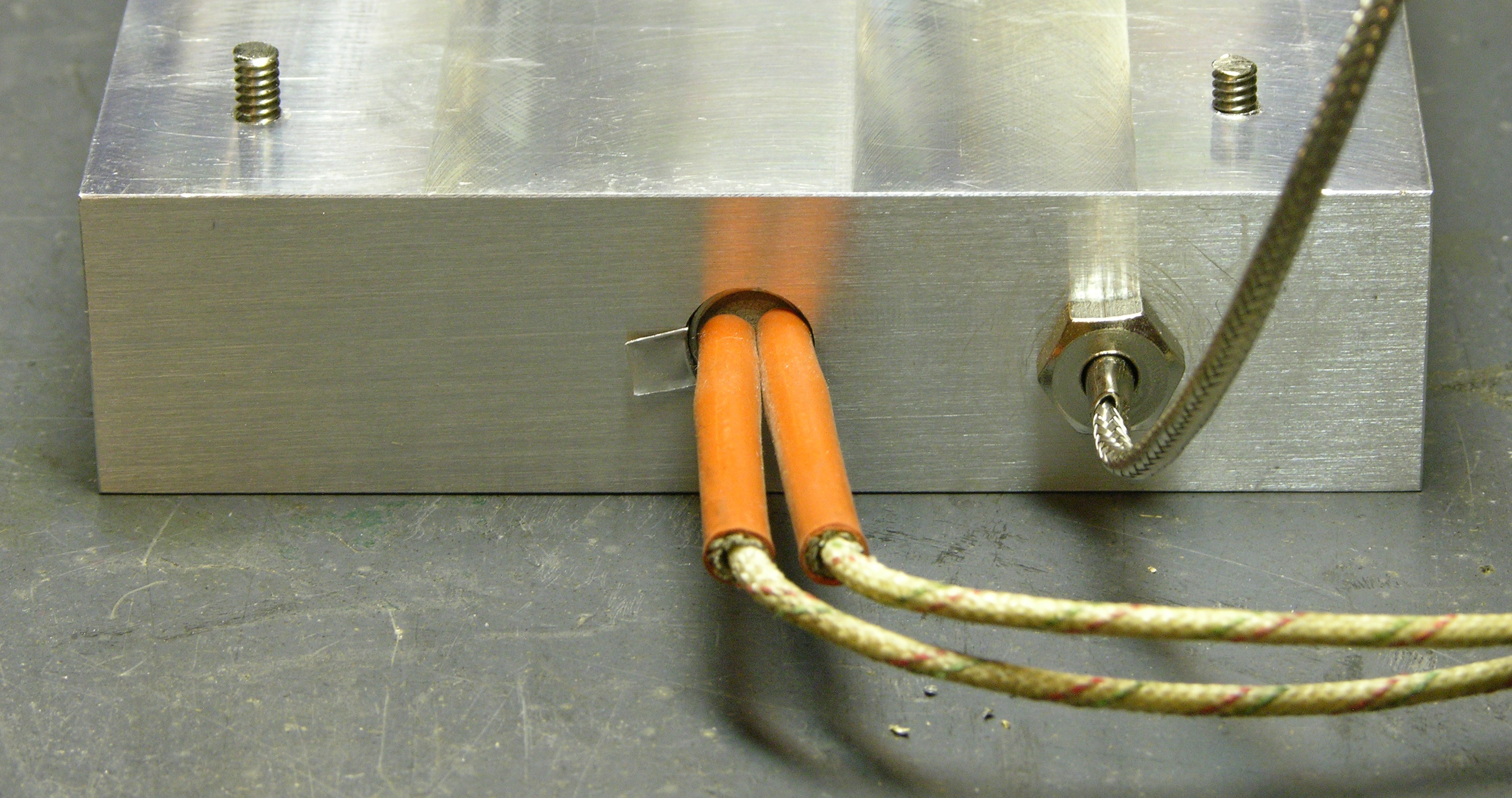
ANYWAY, my brother does more metalwork than I and has a nice drill press vise, so I used his setup and his longest 3/8″ bit to sink a hole for the heater, then measured the metric threads on the thermocouple and drilled and tapped a hole for it as well. The heater hole ended up a bit loose, so that’s a sliver of Mug Root Beer can sticking out the left that shims up the gap.
Ceramic Standoffs
Copying Jeff’s design, I wanted to use ceramic spacers to provide thermal insulation between the hotplate and the base — and he had trouble in his first iteration with too much heat conduction through his 1/2″-diameter standoffs and was much more satisfied when he switched to 1/4″ standoffs.
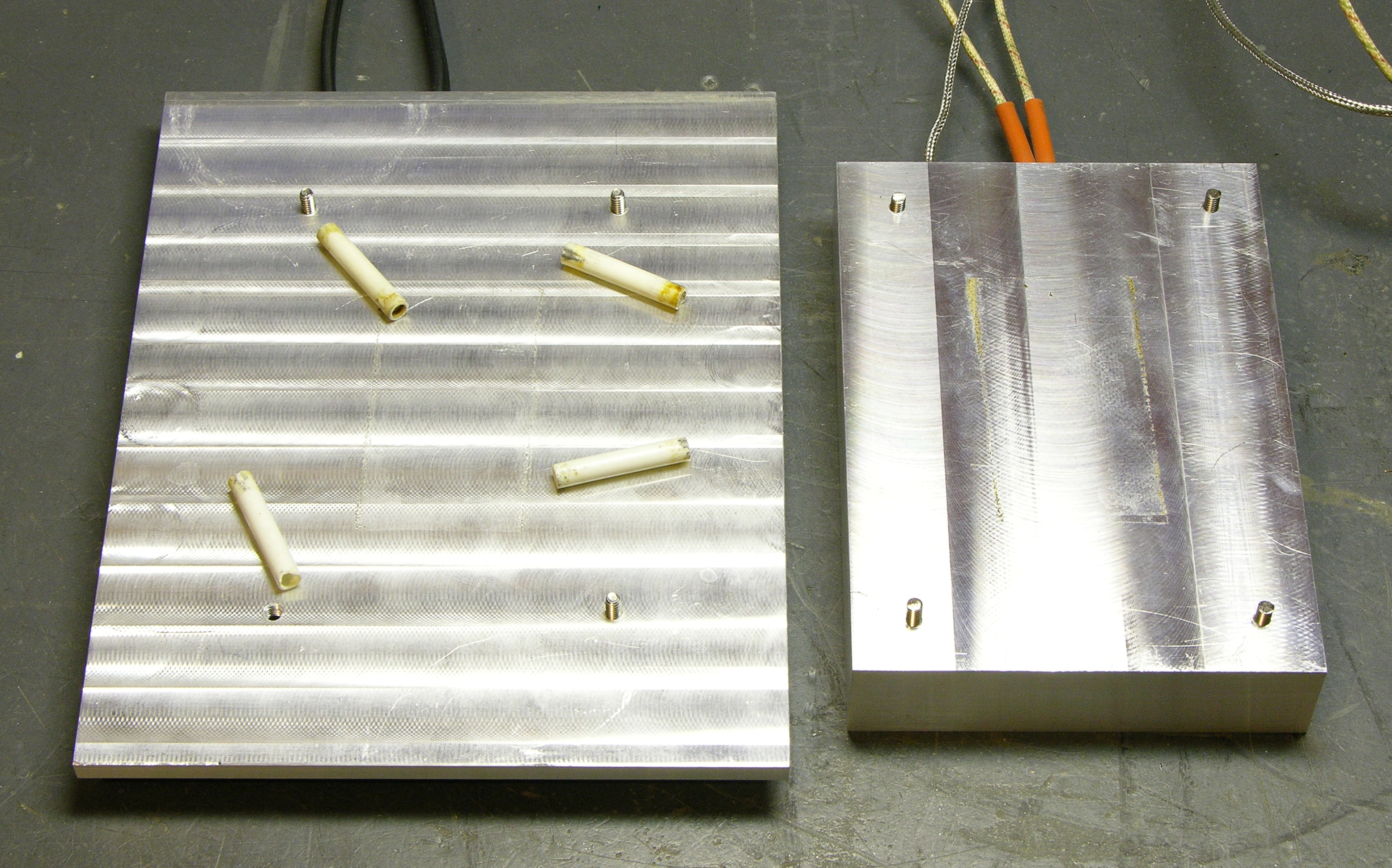
I couldn’t find any 1/4-3/8″ standoffs and didn’t really want to order from McMaster-Carr just to get going, so I pondered alternative sources of ceramic tube. Finally I hit upon a solution — high-amperage, ceramic-cased fuses. Grind the metal caps off the ends and you have 1/4″-diameter ceramic tubes.
I know glass tubing would be a good insulator too, but I figured the glass would be too fragile. Even using ceramic, I shattered two tubes yesterday afternoon grinding the metal ends off of enough fuses to end up with six tubes.
Again taking the nod from Jeff’s work, I used stainless steel screws (low thermal conductivity) tapped into the aluminum blocks and set loosely into the ceramic tubes — gravity currently holds this together, not mechanical fasteners.
Oh, and I botched the first hole I tapped, grabbing the 8-32 tap from the wrong end of my tap set and wondering why I needed to redrill the pilot hole larger than what I had looked up earlier. (Lower left in the picture above, missing the machine screw.)
Firing It Up
By early evening I had everything bodged together and ready to go. After triple-checking my wiring, I turned on the power strip and there was no popping or puff of smoke, so it was fine so far. ![]() I set it for 20°C and watched the OUT1 light wink, wink, wink, and the temperature climb up to 20°C … and overshoot a few degrees … and come back down. The block felt cozily warm.
I set it for 20°C and watched the OUT1 light wink, wink, wink, and the temperature climb up to 20°C … and overshoot a few degrees … and come back down. The block felt cozily warm.
Occasionally OUT2 would turn on for a while and I’d hear the click of the relay.
I set the controller to 40°C and it took a few minutes to climb, then overshoot all the way up to 49°C. I think we need to do a little tuning on the parameters, but there’ll be time for that later. The plate was hot to the touch but not unbearable. No smoke or bad smells — I was at least expecting the heater to burn off some coating or grease or something, but nothing objectionable seemed to be happening — so I figured it was time to go for it.
Jeff’s blog says that 60/40 solder melts around 185°C, so I bumped the controller up to 190°C. Around 130°C, water droplets boil from underneath fast enough that the combination of rising steam and the surface tension of the remaining drop keep them intact and dancing across the plate nearly indefinitely until they roam off an edge. (Somebody find a video of this and post a link in the comments? It’s a really wild effect if you haven’t seen it before.)

At 185°C the solder in the salvaged PCB snippet’s through-holes was melted, and I could melt more of my ultra-fine (15-mil) solder into it. At 190°C I could melt solder onto the tinned area, and at 200°C I could melt solder onto the bare copper I had exposed by sanding away the varnish. After a few minutes the copper had oxidized too much and I could no longer easily melt solder into it.
At no point was I able to melt solder onto the copper on the bakelite board; and by 200°C, the board was starting to darken from the heat. It appears that bakelite is too good a thermal insulator to be able to reflow solder on it by heating only from below, which is disappointing as I have large amounts of single-sided bakelite board that would be perfect for SMT prototyping.
The base plate remained cold to the touch the entire time — apparently the fuse “standoffs” are plenty poor thermal conductors (good insulators) and are doing their job.
Cooling Down
When I was done playing, I was curious how long it would take to cool down. Rather than power it off, I changed the set temperature to 25°C so it would no longer heat but would still display the measured temperature. The OUT2 LED came on solid. We went to drop my wife’s Jeep off at a transmission shop out in the country; and when we returned 45 minutes later, the temperature had only fallen from 200°C to 60°C.
That’s a long time to wait for the block to cool. When using the hotplate, I may want to run specific heating/cooling profiles to prevent damage to components; and there’s even the simple safety factor of having a very hot, not visibly hot aluminum block sitting on my bench.
I hooked a salvaged 4″ fan up to my bench power supply and set it in front of the hotplate, blowing between the block and the baseplate. Within a few minutes, the temperature had dropped to 25°C.
Plans
I need to enclose the electrical parts in a case, and I think I have an avacado green ancient modem that would be perfect for this. The PID controller is only 2″ square on the face, and I’m sure I have some vintage device (if not the modem) that would provide a suitable housing.
It would appear that OUT2 is intended to control a cooling device, just as a car has both accelerator and brake. Because the base plate is staying so cool, I think I’d like to build the hotplate onto the top of the controller housing, sort of like a solder pot. I intend to build a fan into the housing to blow across the underside of the block under control of OUT2, hopefully far enough from the block that the fan doesn’t melt from radiant heat.
The block is a bit wobbly on its standoffs — the fit between the #6 screws and the fuse tubes isn’t as tight as I’d like. If I were going to keep this in the current configuration, I’d want to find someone with a lathe to turn part of the threads off of #8 machine screws until they fit snugly into the tubes without cracking the ceramic, then redrill and retap all my holes to #8. But because the heater block will really need to be sturdy if it’s mounted on top of the controller housing, I’ve ordered tapped (6-32) ceramic standoffs from McMaster-Carr (at $3.42 each, good grief!).
The system took about ten minutes to heat to solder’s melting point, and that’s longer than I think I’m going to be happy waiting. I still couldn’t find a suitable 400-500W heater on eBay for cheap, so I ordered one from McMaster-Carr for $27. I went with 500W — the pulse-modulated controller output can always deliver less average power if I don’t need so much, so I’d rather overkill and scale back than undershoot.
I’d been hoping to do this on a budget; and although I don’t regret having built it, it certainly hasn’t turned out to be a budget job.
| PID controller | $40 |
| solid-state relay | $8 |
| aluminum block | $5-10 (I think) |
| 250W (@ 120V) heater | $18 shipped |
| prototype total | $71-76 |
| new actually 500W heater | $27 |
| new standoffs | $14 |
| shipping | $10? |
| rebuilt total | $104-109? |
The materials I’ve used only in the prototype aren’t necessarily a waste — Cort wants one of these too, and he may be satisfied with the slower action of the 250W heater. He may also like the remote plate design that’s lower to the workbench than mounting the block on top of the controller, so he may use my fuse standoffs (and we’ll do up some #8 machine screws for him).
So … I’m disappointed that the total comes to as much as it does, because I think it may be prohibitively high for other folks who would otherwise want to make one too. eBay prices on the PID controller and the SSR are very competitive with online retailers; and since I was already shopping eBay, I just don’t know that we can get the prices for the expensive bits much lower.
But I’m delighted to have a working, temperature-controlled hotplate, and I’m eager to get going on the CupCake soldering.
It has surprised me that you’ve actually found the one and only proper use for root beer (and cans). Using the can as shim stock and (hopefully) getting rid of its contents in an environmentally friendly way.
Good post BTW.
Nice build. I had no idea PID’s were so cheap these days. I may have to investigate the possibility of making one of these.
Also… I would use a fan on the underside of the plate to assist in cooling. On top would result in cold joints or thermal shock which is bad.
If you wanted to go nuts, you could use a liquid metal to both heat the plate and cool it off. Mercury boils at ~350C so you would be fine unless you need it that hot! Now that’s a mad-scientist worthy reflow plate if you ask me!
Keith – Could you publish a part list for this project, including the sources you used for the parts?
Thanks – Jordan
Jordan, the parts list is pretty much what you see in the table at the bottom of the post (including the solid-state relay that isn’t visible in any of the photos), plus wire and wire nuts and four rubber feet.
The PID controller and SSR both come from Sure Electronics on eBay, and they have both of exactly the same devices listed on current auctions.
I got the aluminum from a local aircraft surplus / scrap yard. I have no idea what to suggest if you live somewhere other than Wichita or Seattle — find a machinist; he or she will know.
Hope this helps!
http://www.uoregon.edu/%7Elinke/dropletmovies/index.html
Dancing water is the leidenfrost effect. Pretty cool, and also largely unpredictable.
Maybe a frimware error prevents the controller from taking a setpoint higher than 400 Deg no matter what the units used.
Sean
Nice writeup! I have used the professional version of these at work for years, and this looks to be at least as good. I should make one for home.
Have you tried solder paste? (it’s little nearly microscopic balls of solder in a paste flux) It helps stick the SMT parts down, and you can dispense on each SMT pad with a manual syringe, a pointy stick (a toothpick) or a pneumatic dispenser. You then place all the parts on their pads and heat the whole board up all at once on your hotplate. Keep a watch out for tomb-stoning, where one edge solders first and lifts the other one up like a grave stone. Creepy. A poke with a probe to push the part back down usually helps.
Thanks for the writeup!
Neil — see the very next post (just now published over lunch) for my first solder paste experience.
Here’s an Ardunio PID design, I’m sure with some modification and tinkering it could be used in a similar setup.
http://www.arduino.cc/playground/Main/BarebonesPIDForEspresso
Very nice! I really like the writeup of how PID works.
Matt, I’ve thought about alternate routes to PID control; but even with a $2 ATtiny, I’m not sure how much you’re going to save on a $40 commercial unit by the time you have a display and buttons too.
I’d love to fall into a batch of 500W 110V heaters in the back of an old hardware store somewhere …
Nice project.
I’ve started making a smt reflow plate myself, also for the cupcake boards! (Mine are still stuck in customs)
I’ve got pictures, tuning responses and thermographic images here if anyone’s interested:
https://sites.google.com/site/mechatronicsguy/reflow-skillet
Just out of curiosity, does this offer any advantages over the hotplate approach, given that seems to be somewhat cheaper?
The Snob, the PID controller has much greater accuracy than the bang-bang controller built into an electric skillet. Have a look at the temperature graph on Gav’s page (the comment above), then realize that the PID controller keeps the plate within less than 1°C variation once it reaches the target temperature.
If you have sensitive components to solder, the difference could matter.
As to whether the block is advantageous over the skillet shape — nah, not particularly. I just couldn’t find any remotely suitable electric skillets in my area. I do like the small footprint my finished hotplate will occupy on my workbench.
This is a great example of the power of PID loop controllers. They can literally control just about anything. Most can actuate two devices simultaneously (Well my Eurotherm 3216e can) using PWM, hysteresis or whatever else. Many also have a comms card so you can send and receive data over RS485. I would say to anyone considering this type of controller to go for it.
Great writeup! I’ve been using a regular old toastmaster hotplate(with an element like you’d see on an electric stove) with a small frying pan set on top. The good thing about my setup is the heat-up and cool down are very quick. I can be soldering in under 10 minutes without having to worry about burning myself a few minutes after I’ve shut it off.
I’m thinking about doing a similar PID setup with my hotplate/frying pan combo so that controlling the temperature is easier. I had no idea that the prices on PID’s had come down so much – nor that there was an arduino solution, either. At any rate, you’ve given me some inspiration…
i’ve been looking at several posts throughout your blog and will continue to follow it, as well as your new bus project blog. i am teaching myself electronix and find your posts very informative and helpful. my experience is limited at this point so i probably won’t be commenting often (if at all) but wanted to say i appreciate your efforts & look forward to reading more!
I absolutely can’t get enough of this blog… great stuff. I am absolutely fascinated by the mix of electronics, hardware, mechanical and physics all rolled into one.
I’ve not got many hours of enjoyable reading, not to mention so many ideas you’ve inspired.
Vielen Dank!
Adam, bitte sehr! Glad you like it, and thanks for the kind words!
My comments are only for safety standpoints.
1) The PID controller is rated 7VA max at 120Vac, then a 10A fuse between mains line and the device is needed as recommended by the manufacturer.
2) An overcurrent & overtemperature protection device is needed cutting off the current going to the heater in case the PID malfunctions and cause a temperature run off to the hot plate.
3) A metal case contains AC inlet, 10A fuse in 1), and covers the PID from exposing hazardous voltage. It also protects the PID.
Sincerely
Nice job. I have also done work with reflowing via hotplates and noticed one major drawback: speed. The controllability of the thermal system relies on a few key parameters.
An ideal hotplate will have a lower thermal mass, but sufficient to allow an even heating surface. Secondly, the most powerful heater possible would be ideal. Then, finally, the coupling between the heater and the plate is critical. Any hotspots will cause tremendous warping action.
My two cents
You should use “exhaust wrap” around the edges and on the bottom of the plate. The ceramic based stuff. That will reduce losses from room-temp diffusion and focus the heat back up through the block. That should also make your thermal sensor more responsive.
If you can program the controller… You want it to pulse less as it approaches near temperature. As opposed to running full force up to temperature, and then pulsing to regulate. (There is a thermal delay as the metal acts as a buffer. You are only interested in the average temp anyways.)
If you get a Pyrex dish as a cover, you can save power and alternately use it as an “oven-bake” tool also. Use a deep-pan which covers the whole hot-plate, including the thickness. Attach a pivot-point on the base to hold one end, and a coat-hanger handle/stand for the other end. When you open it up, it should rest on the pivot and be braced or removed to a pot-holder. (NOTE: Using a pot-holder over the top of the upside-down Pyrex cover will help retain additional heat for faster baking and allow quick viewing when needed.)
[...] I've been working with SMD soldering for quite a while, however all my experience has been with a soldering iron, microscope and solder wick. An alternate approach that is gaining ground for the 'amateur' is using a hotplate. Some people use cheap kitchen hotplates from Target and convert them. However, I'd like to have a go at making something more substantial. After some searching on the web, I came across Keith's electronics blog. Photo of Keith's Hotplate Inspiration for this project was obtained from Keith's Electronics Blog. After seeing his approach, I realized that I would have to make one myself. My friend Scott also wanted one so we decided to make two at the same time and hopefully prevent each other from making mistakes. Link to Keith's excellent website and his post: http://www.neufeld.newton.ks.us/electronics/?p=537 [...]
Regarding the CD101 – a lot of people are using it for Sous Vide DIY waterbaths, and a better manual for the weird hidden settings has been found:
http://seattlefoodgeek.com/wp-content/uploads/2010/02/CD-101-Instruction-Manul-including-PV-adjustment.pdf
Matt, thanks for the link! Interesting timing, too, since I just ordered submersible-probe K-type thermocouples to try some DIY sous-vide cooking with this PID controller.
You’ll do much better with the PT100 probes for Sous vide – K thermocouples are +/- 2c accurate, whereas resistive types are +-0.1c.
BTW: you can set the low/high values for the SV in the menu under LCK(1000)->CODE 0001->SLL and SLH. The values persist for C and F, so if you want a Farenheit reading, you’ll have to increase this value.
Weirdly, mine appears to read correct for F but not for C. I can set a bias voltage but the point of the whole endeavour was to build a really accurate system!
@Matt S I hope I’m not hijacking a thread, but it looks like you have the answer to one of my questions. Could you go into specifics on how the modify from C to F? I believe the default is Celsius and can’t figure out how to change it. Thanks!
Greg,
You can set the CD101 to Fahrenheit mode by changing setting SL2 to 0001. That’s how mine came configured, and it took a while of poking around to figure out how to set it back to C (SL2=0000). This isn’t documented in either of the datasheets I have.
To access the SL parameters you need to hold down SET and R/S for a few seconds, then set Code to 0000 and push set to get to the desired parameter.
More CD101 trivia: to disable the 2nd output (mine came configured to fire OUT1 and OUT2 in heating mode), set SL6 to 0001. This stops the controller from audibly clicking every few seconds (it was driving me nuts).
One thing I haven’t figured out yet – if I hold down R/S to STOP the controller, the outputs are still active! According to the docs, this should disable the outputs. What happens when you guys try this?
Keith -
Have you seen any evidence of corrosion between the thermocouple and the aluminum block?
Sure claims that the sheath is stainless, but it’s magnetic, so I don’t know if I believe them. They also don’t spec the material of the sensor probe and threaded sleeve.
I ask because I recently took my hotplate apart to work on it, and I had a screw snap off where I had connected the ground strap. I used plated steel fasteners for all but the bottom standoffs, and every steel fastener shows some degree of corrosion. I’m thinking about using the thermocouple probe that Sure sent, but worried that I might see more corrosion problems with it.
Jeff, I think my hotplate has seen much less duty than yours. No signs of corrosion yet; but I wouldn’t expect it, as lightly as I’ve been using it so far.
I wonder if you put a hi-temp-rated pyrex dish over the PCB the convection of air would help the topside soldering.
Maybe a larger pyrex cooking-ware square dish updised down with standoffs from the top of the aluminum plate block. The hot air would be trapped rising upwards, but could vent if needed.
Lee, that’s a really interesting idea; thanks! I like being able to move things around and poke solder bridges while it heats, but that’s definitely worth considering.
Hello i am building a powder coating oven that will have to stove elements in it i have the cd101 pid controller and a 240 ssr and i am lost on how to wire this thing can you help me please I got the main power to it and the TC hooked up just not sure what out post to use to run into my relay and how if you can help it would be great thanks, John
What are the values of the two resistors in the output circuit #1? .. its the first board picture below the relay for the second output. Thanks.
Eric, I don’t have it apart, but you can click on the picture to zoom. I see brown-black-brown and brown-brown-black-space?-black-green.
Hi there Keith,
I went through your post and was wondering if you have a wiring diagram of your PID controller connections. Im working on a similar setup with heat plate, 2 heating elements (unsure whether to wire in series or parallel) and a type k thermocouple. My controller also has out1 and out2 but not sure which one works best for what im looking for. Help would be appreciated
Aaron, my recollection is that out1 controls the heater relay and out2 controls the cooler relay (which of course I don’t have). So you’d (probably) connect out1 to the input of your solid-state relay.
Hi Keith,
This old post of yours is so helpful and informative!
Currently I needed to set up similar hotplate/chuck and I found your post.
It would much helpful if you share the wire connection bettween PID, SSR and Cartridge heating unit.
thanking you in advance!
Hi Keith,
I have throughly looked over Fred’s and your PID controlled hot plates using a
cartridge heater. Simply awesome projects!
Unfortunately, I am not a pro sparky like you and Fred. If either of you could do a wiring schematic for your hot plate projects, that would be awesome! My nickname is this realm would be ‘smoked-it’. Or Great-Balls-of-fire!
I am at this level of sparky knowledge:
https://youtu.be/1P6hqQWd3Vw
My motivation for doing this project comes from buying a welders ruler from the famous youtube ‘Ave’ above. It comes with a 1206 LED smd electronic component 1206 LED to solder on in the form of a mini kit that comes with his ruler. You need a microscope to see this little part. I want to do other electronic projects and experiments also with the hot plate. I am nearly done converting an old computer power supply into a bench supply so my soldering skill is improving some and no blue smoke yet
For instance, one of you used a panel mount 110v female socket with a line filter attached. I am not sure how that is wired to the Sure Pid or SSR. I am not sure how your going to wire a 12V fan to your Pid. A wiring diagram would really help a novice like me out.
Since Fred is now using the same Sure CD101PID since his Omega PID died.
I am going to eagerly follow the two of your improvements/updates to your hot plate projects.
Thanks guys!
Bill Mac
I am using the same CD101 from Sure. I bought two and they both exhibit a behavior that prevents me from getting my system going. When the current temp is under the set point, I see 12VDC on the OUT1 terminals (5/6) as expected (PID is calling for heat). However when cooling is needed, I also see 12VDC on the same OUT1 terminals. This means my SSR is on when heat is required and when cooling is required. When neither OUT1 or OUT2 LEDs are on the terminals show 0V (as expected). Is it possible there is a parameter I need to change so OUT1 terminals only have voltage when OUT1 is on?
I did find workaround (for the moment). The SL6 parameter was set to “0011″ from the factory. According to the limited docs supplied with the PID, the first bit controls “direction”. If I change this bit by using “0010″. The PID OUT1 and OUT2 are reversed (as expected). So now when heating is required the OUT2 LED illuminates and when cooling is required the OUT1 LED illuminates. This doesn’t help me since I still get 12VDC on the OUT1 terminals when either OUT1 or OUT2 are on. So I but that bit back to 1 and tried flipping the undocumented bit 2. I tried SL6 = “0001″ and now OUT1 comes on when heat is needed and OUT2 never comes on. So for the moment this gets me going since I have not yet added active cooling. I still would like an answer if anyone knows how one is supposed to differentiate the heating and cooling states.