A few weeks ago, John mentioned to me that one of the audio mixers in the art and technology / Internet radio station lab had stopped powering on. I said I’d have a look at the power supply and see if I could fix it, and he sent it with me. Turns out we both got a little more than we bargained for — I in terms of effort required and he in terms of time without the mixer.
I didn’t know whether it’d be a linear or switching power supply, and it turned out to be switching. I figured it’d just have some baked electrolytic capacitors I could replace, and it turned out that was just the beginning.
I’ve got it mostly fixed now, and it’s been a long and interesting road.
Getting In
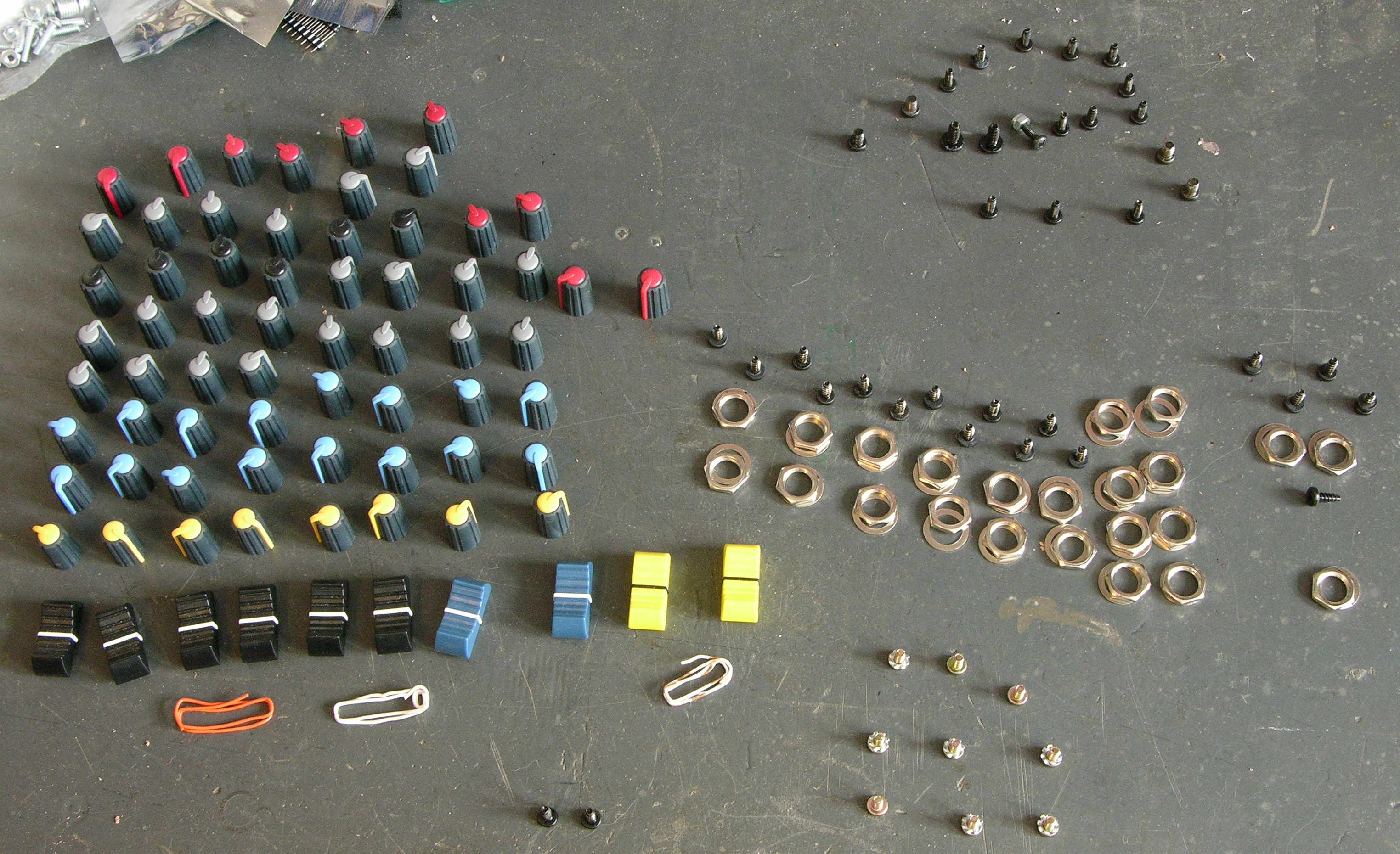
First off, you can’t get into the mixer from the back, so I had to take every knob, screw, and nut off the front panel. I’ve had this assortment on my workbench for several weeks, in the way and patiently waiting for reassembly.
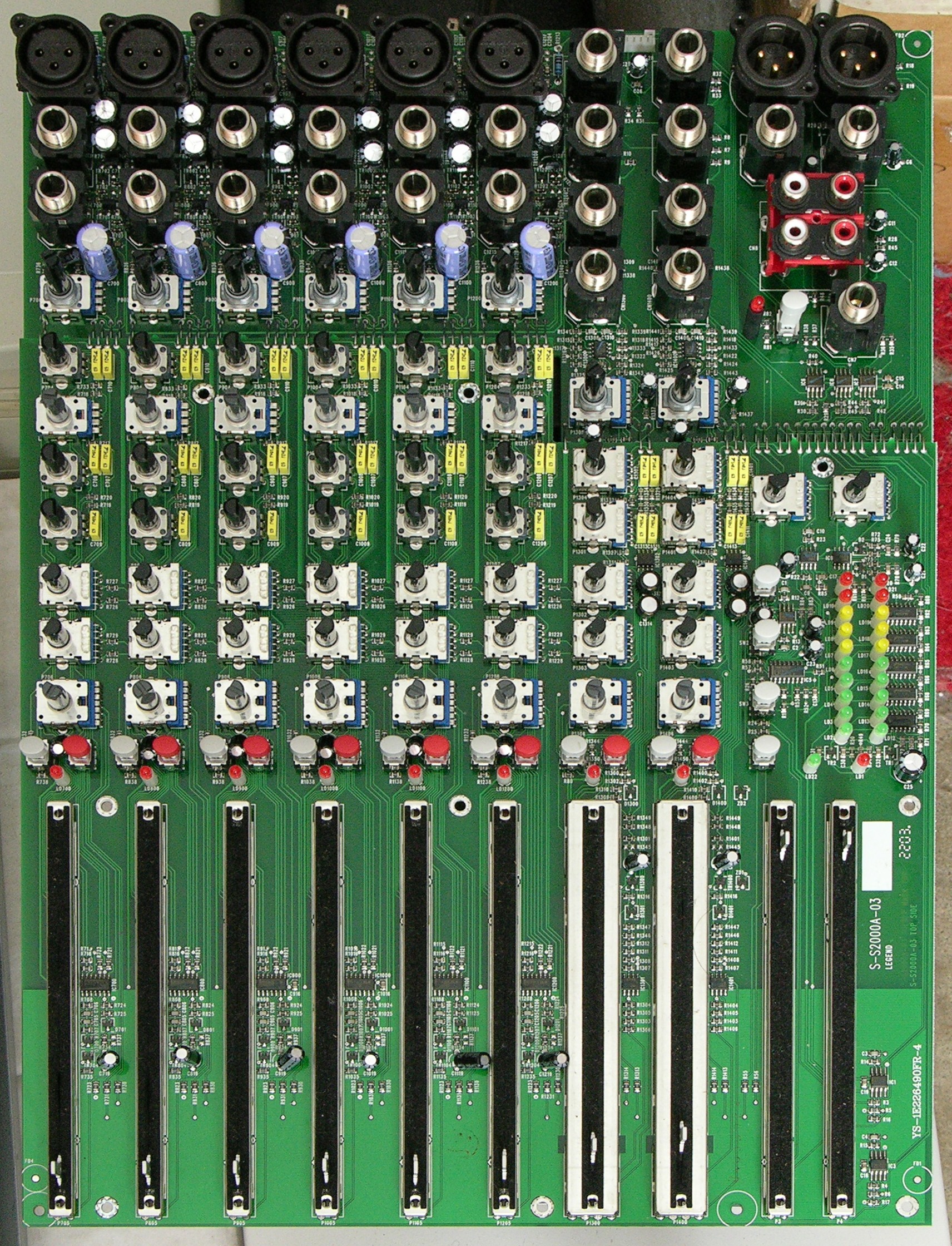
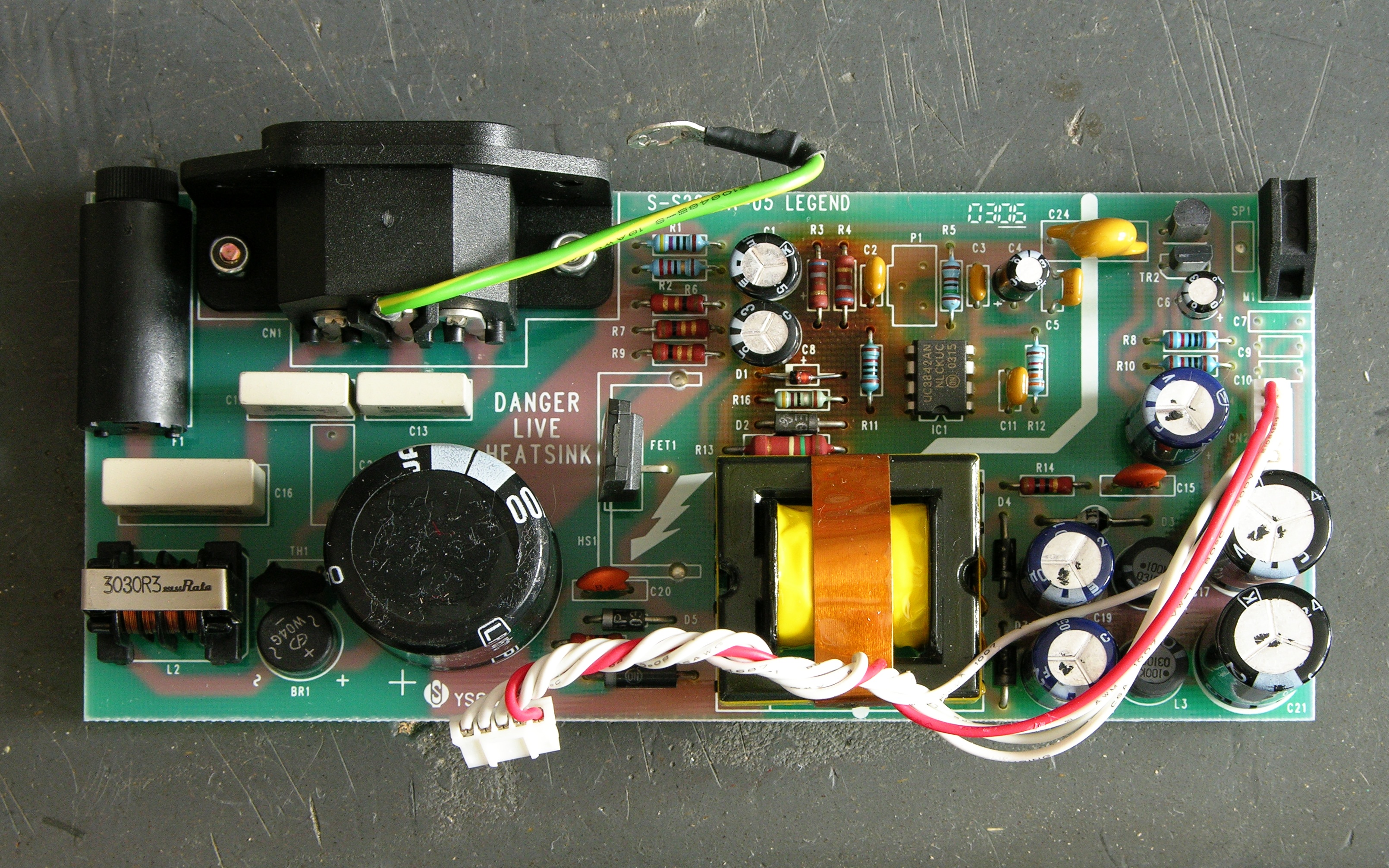
Here’s the main board. It’s so hard to see the active components, it looks almost like it’s just a control board, but that’s the whole deal — all the op-amps are tiny little SMT jobbers hiding between the jacks and faders.
Then I had to dig the power supply out of a gully in the back of the case — yet more screws to keep track of.
Capacitors
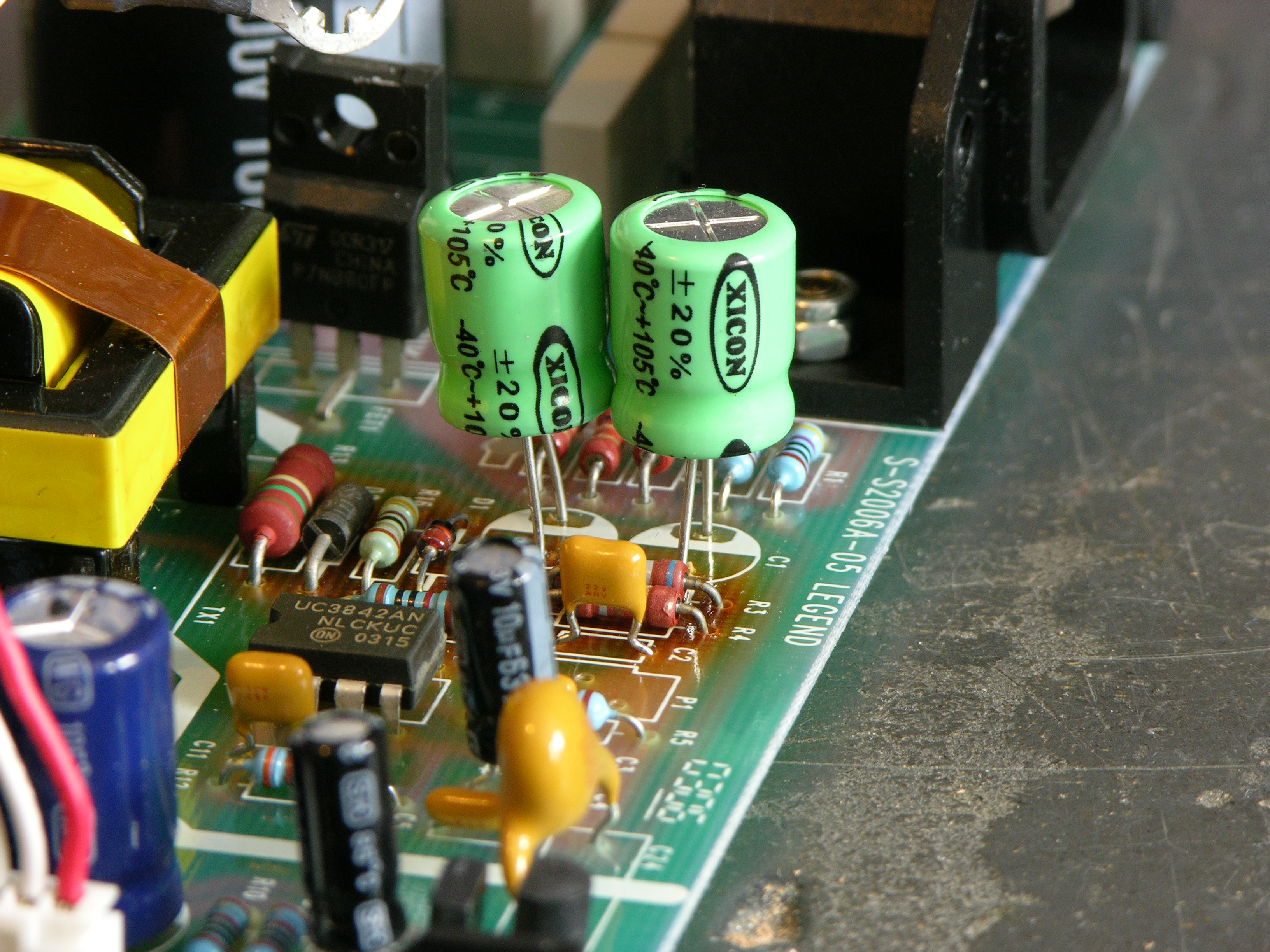
See that scorched area in the upper middle of the board? I was suspicious of the two electrolytics right next to it.
I pulled out Ye Olde Capacitor Wizard, and sure enough, C1 and C8 (47uF 63V 85°C) both tested way bad. I replaced them with 47uF 100V 105°C capacitors, raising to get them a little further away from the resistors that I assumed were the source of the heat. This is probably not kosher, but then neither is failing to take thermal considerations into account and baking the capacitors.
And voom! The power supply … er, still didn’t work. Durn.
Sam’s Switching Power Supply Repair FAQ
Since I knew nothing about switching power supplies other than vague theory — and at the time still had every desire to keep it that way — I Googled for “troubleshooting switching power supplies” and went off to read Sam Goldwasser’s excellent troubleshooting guide. It even has a section on the UC3842 control chip used in this supply.
Alas, none of the problems that “probably account for 95% or more of the common SMPS ailments” seemed to pertain. (I find that they don’t 95% of the time.) Under “Supply dead, fuse not blown,” it suggests a bad startup resistor, bad fusable resistors, and bad controller components.
Startup resistor — okay, now I was having to learn a little more about how off-line switching power supplies work.
In an off-line power supply, ac line voltage is rectified and filtered without using a line frequency isolation transformer. Great; not only is there 110-120VAC in there, and 155-170VDC, but the entire primary side is powered by directly rectified AC and is “live” with respect to earth.
I’ll say it now and I’ll say it again later — don’t poke around in a powered-up off-line power supply unless you have it plugged into an isolation transformer. You don’t want to chance touching a connection that’s hot to earth and having it short through you. You also don’t want to connect the power supply’s floating ground — which is still hot with respect to earth — to your scope’s ground; it’ll send a whole lot of electricity through things before it melts one, the other, or both. For safety’s sake, you’re best off using a battery-powered meter, which doesn’t provide any return path to earth.
Right, back to that startup resistor. In this type of supply, the primary side of the circuit is running off rectified line voltage — in this case, about 170VDC. A high-valued startup or bootstrap resistor is used to provide VCC to the control IC — in this case, as I learned shortly, by charging C1.
The UC3842 control IC is designed so that it turns on when VCC climbs to 16V, increases its current consumption so it’s now draining C1, starts driving the FET to power the transformer primary and hopefully get the supply bootstrapped, and turn off if VCC falls to 10V by depleting C1 before the main supply manages to bootstrap. This is why failed switching power supplies sometimes chirp, chirp, chirp or flash their power LED — which I found out later this one had been doing before it went completely dead.
Once the system is bootstrapped, it draws from a transformer secondary to power the control IC on the primary side.
Startup resistor — right. A bad startup resistor could make the supply never bootstrap. In retrospect, it makes sense that it’s the large resistor in the circuit, because it’ll have about 170V dropped across it, but I wasn’t thinking of that at the time. Which leads me to …
Building a Schematic
Didn’t have one. Needed one. Made one.
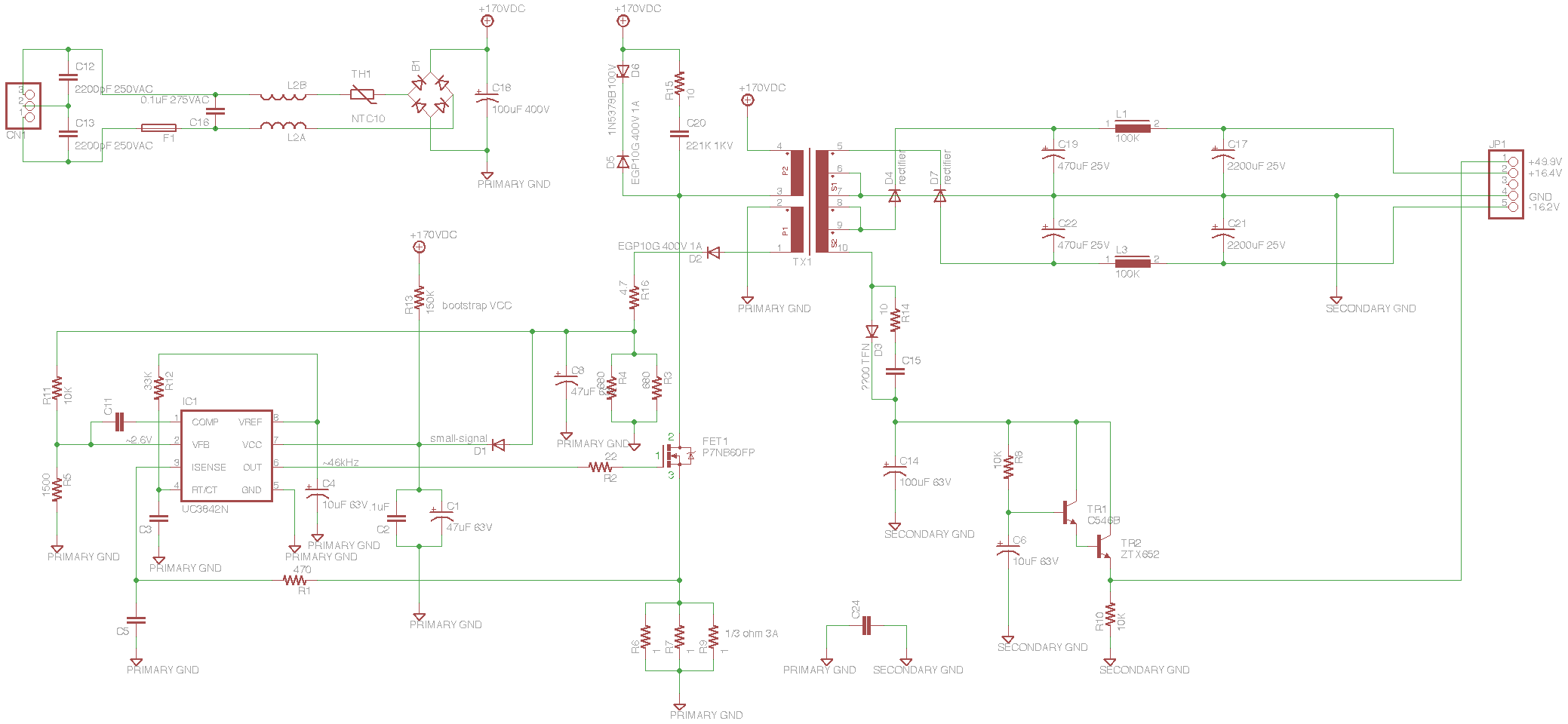
I looked at all the components on the board, placed them in EAGLE in corresponding positions, and then joined connections to follow the traces on the board. Then I rearranged the schematic by logical sections, and that’s what you see here (since annotated with voltages you should see at different points in the circuit, for the sake of the next person to repair one of these).
The whole thing makes a lot more sense now. In the upper left, the incoming AC has RF filter capacitors across it, a fuse, RF filter inductors (it physically looks like a transformer and maybe technically is but the coils are side-by-side instead of concentric and it has an air core), a thermal fuse, a surprisingly small bridge rectifier (high voltage but low current), and a big 100uF 400V capacitor.
The primary side of the circuit charges C1 through R13 to bootstrap VCC up to the 16V turn-on voltage. The UC3842 drives the FET that switches the transformer primary. A primary-side secondary is half-wave rectified to provide ongoing VCC to the IC, and the rest of the primary side is kitted out with all the various feedback the UC3842 needs to operate.
The secondary side has half-wave rectifiers with pi filters (capacitor to ground, inline inductor, capacitor to ground) to provide balanced ± power to the op-amps in the mixer. The oddball dangly thing regulates the 48V phantom microphone power.
I’ll note that brown bands on brown resistors look grey to me, leading to some intial confusion as to resistor values.
Testing Begins in Earnest: Bootstrap Resistor
With the schematic in hand, I could now make a logical progression through the circuit, testing components in turn, to locate the remaining problem(s). My plan was to test the power to the IC, the FET drive signal, then the transformer primary power, to isolate the problem to the appropriate section of the circuit, and narrow down from there.
First I tested the bootstrap resistor, R13. Looked good — and I desoldered and lifted one lead to be sure I wasn’t being misled by some parallel part of the circuit. Seemed okay.
I wanted to check the actual bootstrap VCC voltage, because I was suspicous that it might be too low to turn on the chip. To do this, I needed to power up the circuit, so I did two things: I plugged the power supply into my isolation transformer so if I accidentally touched part of the circuit I didn’t intend to, I’d just be hurt instead of (potentially) dead; and I plugged the mixer’s main board into the power supply on my bench, to provide a load.
Switching power supplies that have feedback from the secondary voltage to the control IC are particular about having a load. Although this supply does all of its regulation within the primary side, changing the load will change the current draw of the transformer secondary which changes the current draw of the primary which changes how the circuit behaves. It might be okay to run this supply without a load; but frankly I just don’t know enough and didn’t want to chance it.
Powered from the isolation transformer, with the main board plugged in for load, and using my battery-powered meter (not essential since the supply was on isolation, but the handheld meter was the first piece of equipment I wanted to use anyway), I measured a fluctuating 12-14VDC on the VCC line.
This told me that the system wasn’t bootstrapping, as it should have a steady supply voltage once running — but of course I already knew that. What it didn’t tell me was whether I had a bootstrap voltage problem. I was using my digital meter, which doesn’t have a fast enough response to be sure about the exact extremes of a fluctuating DC signal.
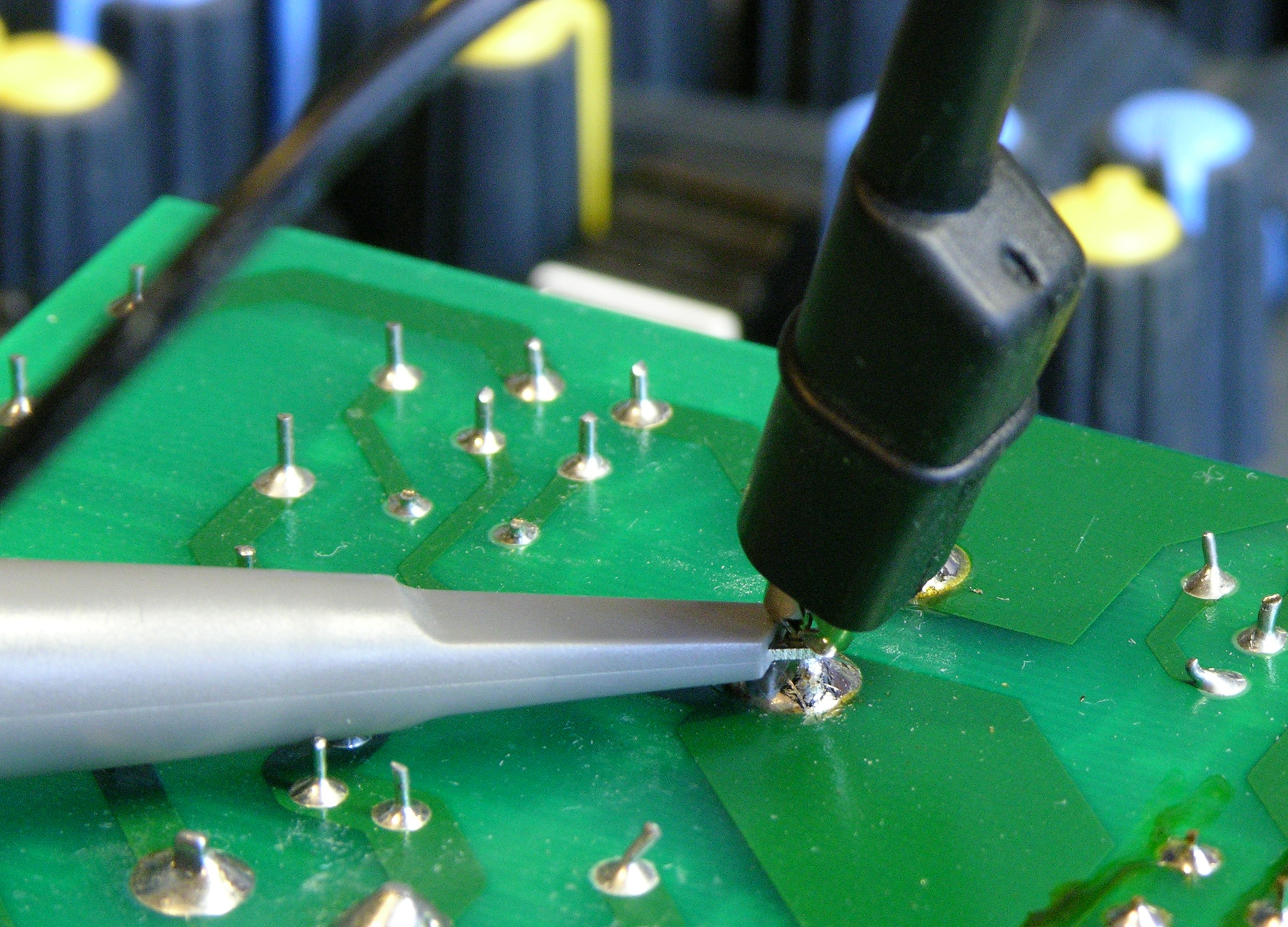
I figured I was going to be spending a fair bit of time testing things on the supply, so I soldered a wire to the primary side’s big capacitor’s negative terminal to use as a ground point to clip my scope’s ground lead to — I didn’t want to try to clip it to a short component lead and have it pop off and touch something else while I was testing.
Scope said 16V falling to 10V on each cycle. Aight, not a bootstrap resistor problem.
Testing the FET
Next I put the scope on the FET’s gate — lack of drive signal there would indicate that the control IC was hosed. I did have drive there:

It shouldn’t be ramping down like that, but that’s just a consequence of the bootstrap VCC draining away C1 as the supply fails to boot.
The next logical point to check was the junction between the FET drain (top) and the transformer primary, but I was still being chicken about hitting that 170V with the scope. Instead, I looked at the cathode of D2, the half-wave rectifier for the primary-side’s transformer secondary that’s the first step in providing ongoing VCC for the control IC.

It’s being filtered by C8, hence the smooth curve — but look at the amplitude. The transformer is providing only ~3VDC to the circuit; that can’t be right.
Now, I didn’t think the transformer was bad, but shorted coils in the primary side’s secondary would result in a lower voltage there and could have this effect. So I measured the ultimate DC output of the secondary side of the circuit — the voltage that was supposed to be going to power the op-amps — and saw it fluctuating from about .5 – .9V. It seems beyond comprehension that all of the transformer’s secondary taps should have shorted coils all at the same time, so I ruled out a transformer problem.
It’s worth noting that I didn’t need to consider a problem on the transformer primary — at least, not any sort of problem I’m familiar with. The two transformer failure modes I’m aware of are an open circuit and shorted coils. An open circuit in the primary side just makes it not conduct and nothing happens at all. Shorted coils decrease the primary inductance and increase the ratio of primary:secondary turns, increasing the secondary voltage (often catastrophically).
Since I had a decreased secondary voltage all around, I assumed there was nothing wrong with the transformer, but rather that there was something wrong with the power going into it.
Back to the FET, then. I still wasn’t ready to poke at the 170V, so I scoped the signal on the FET’s source (bottom), at the junction between it and the current-sense resistors.

Looked basically fine. That is, it was varying between 0V when the FET was not conducting and a higher value when it was conducting. If the FET were broken in a simple way, it would be never conducting (or always shorted), and I wouldn’t see the set of pulses as it pulled up the voltage on the sense resistors.
Fine, fine, FINE. I’ll check the dang high-voltage side.
I did switch the scope probe and the scope to 10x first.

The FET drain looked fine too — 170V most of the time, dropping to about 0V when the FET was conducting.
And I wasn’t dead. Or even injured.
Wait — What Next???
Not a bad bootstrap. Not obviously a bad control IC. Not obviously a bad FET. Not apparently a bad transformer. What the heck???
I spent more time pulling components out of circuit and testing them. C2, the small capacitor that parallels C1 on VCC to catch spikes — tested fine out of circuit. R6, R7, and R9, the current-sense resistors — really 1Ω. D2, the half-wave rectifier for the primary-side low-voltage supply — tested fine out of circuit. R5, part of the voltage divider for the voltage regulation feedback — good. What, what, what.
Bad Zener
Everything on the control side appeared to be operating properly, but the transformer’s secondary voltages were far too low. It really seemed it had to be a problem with the transformer drive circuit, and I wondered whether the FET was weak in a way I was having trouble seeing on the scope — not conducting the full current through, or something.
I found in my parts bin a similar FET also made for ultra-fast switching in power supply applications, albeit at a slightly lower current rating, and swapped it into the circuit. No discernable change. Swapped it back out.

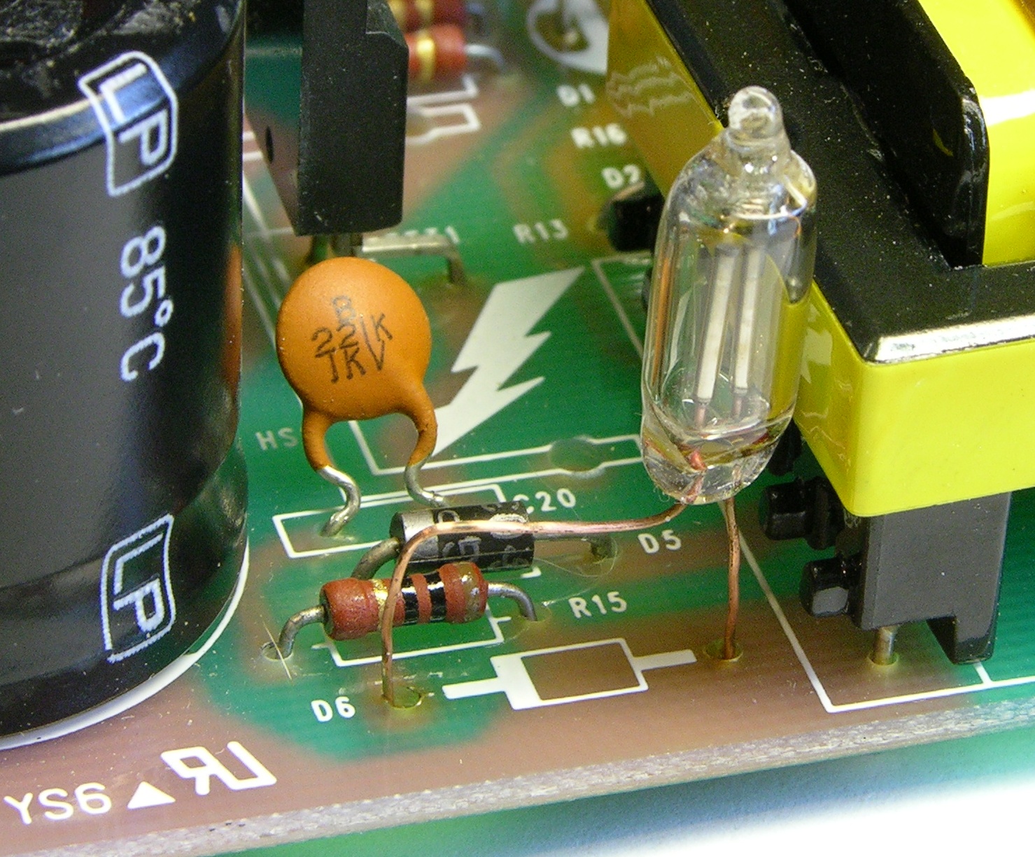
Then I looked up to the network above the FET on the transformer primary — the catch circuit for the inductive kickback. In simple terms, when you’ve been running current through an inductor and you switch off the current source, the inductor wants to keep the current flowing and causes a voltage spike in the opposite direction of your power supply. Placing a reverse-biased diode across the inductor will have no effect during normal operation, but allows the “wrong-way” voltage to be dissipated during the spike, saving wear on the other components.
D5 is that reverse-biased diode, and I hadn’t been able to read a part number on D6 while it was in-circuit (the number was facing down) but knew it must be a Zener — a diode used in reverse, which only conducts (in reverse) when the voltage across it exceeds a certain amount, called the Zener voltage. In simple terms, it clips the (reversed) voltage across it to its rated Zener voltage; or put another way, it doesn’t conduct (in reverse) unless the (reverse) voltage across it is more than the Zener voltage.
So this is a Zener diode, which is used in reverse, applied in the inductive kickback circuit, where diodes are used “backwards,” with the two reverses making it look like it’s used forward — which is why I assumed it must be a Zener. Its purpose must be to shunt the inductive kickback only when it exceeds a certain threshold above the supply voltage, instead of all the time.
I appear to have misinterpreted the function of C20 in this next section. See the comment from MikeS.
C20 is not something I usually see in kickback circuits — the only thing a capacitor can be doing there is catching some of the kickback and adding it to the next forward-going pulse. Oh, very clever! Instead of wasting the kickback by dissipating it all into the power supply, C20 recycles it, increasing efficiency.
And D6 sets the maximum voltage that C20 can catch, discarding the rest. With a traditional reverse-biased diode there, all the kickback would just dissipate through the diode and C20 wouldn’t get to keep any.
I was now wondering whether something was wrong with this catch circuit. It seemed much more likely that one of the diodes would have failed than the capacitor or resistor, so I started with the diodes.
When I measured D6 in circuit, it looked like it was conducting both directions. Oh, I thought, that’s because of other components in the circuit, so I pulled it out and measured it again. Still conducting both directions, a lot. Eureka! There’s the problem — it was dissipating all the kickback through D5, with D6 acting like a dead short, and C20 wasn’t getting to keep any, and C20 was critical to powering the transformer!
Now out of circuit and completely legible, I could see that D6 was a 1N5378B 100V Zener. I couldn’t find anything in my parts bin close to an acceptable substitute, and I didn’t want to place a parts order until I was sure that was the last thing wrong with the supply and I didn’t need to buy anything else, so I really wanted to find a substitute and check. And I had a feeling there was something else I could use, but I couldn’t think of what it was.
Faux 100V Zener
The next day I talked to Tom McGuire and John, asking if they had any 100V Zeners at work and whether they could think of anything else I could use.
They didn’t have any Zeners big enough. Tom seconded my suspicion that I could probably run it without the Zener long enough to test, letting all of the kickback go into C20 instead of shunting some; but I didn’t want to take a chance of breaking something else in the circuit at this point, so I was leery of trying that.
And then Tom reminded me of what I couldn’t think of — a neon bulb.
A small neon lamp will start conducting when its voltage exceeds about 100V (perfect!) and keep conducting until the voltage drops below maybe 60-70V (unimportant for this application). They have a long history of being used as voltage regulators in addition to indicators.
With the shorted Zener out of the circuit and the neon bulb in, the power supply worked and the mixer powered up! I couldn’t ever see the bulb light so it’s possible the kickback was never exceeding 100V, or never for long enough to light up the bulb, but I felt better having it there.
I poked around the rest of the circuit and everything else looked okay. I placed my Digi-Key order for some other stuff that had been accumulating on my shopping list, got the order yesterday, replaced the Zener, and now the mixer is tip-top!
Well, actually no.
10MHz Ringing
I was going through taking measurements of correct, baseline voltages and frequencies to add to the schematic for posterity, and I noticed that the VCC line looked awfully noisy. I zoomed in on it and found massive ringing, with the leading spikes happening at a period that appeared to correspond with the FET switching frequency and the individual oscillations in each ring at about 10MHz. I rechecked all the capacitors, replaced some anyway, supplemented some, and absolutely couldn’t get the ringing to go away.
Now, 10MHz is way above audible frequency (except perhaps for golden-eared audiophiles ![]() ), so I wasn’t worried about hearing it. Plus it was only on the primary side of the circuit, so I was pretty sure it couldn’t couple through the transformer to the secondary. But I didn’t figure it was great for the control IC to have that on its supply, and I was worried about it shortening the life of other components. So I really wanted to get it figured out before closing up and returning the mixer.
), so I wasn’t worried about hearing it. Plus it was only on the primary side of the circuit, so I was pretty sure it couldn’t couple through the transformer to the secondary. But I didn’t figure it was great for the control IC to have that on its supply, and I was worried about it shortening the life of other components. So I really wanted to get it figured out before closing up and returning the mixer.
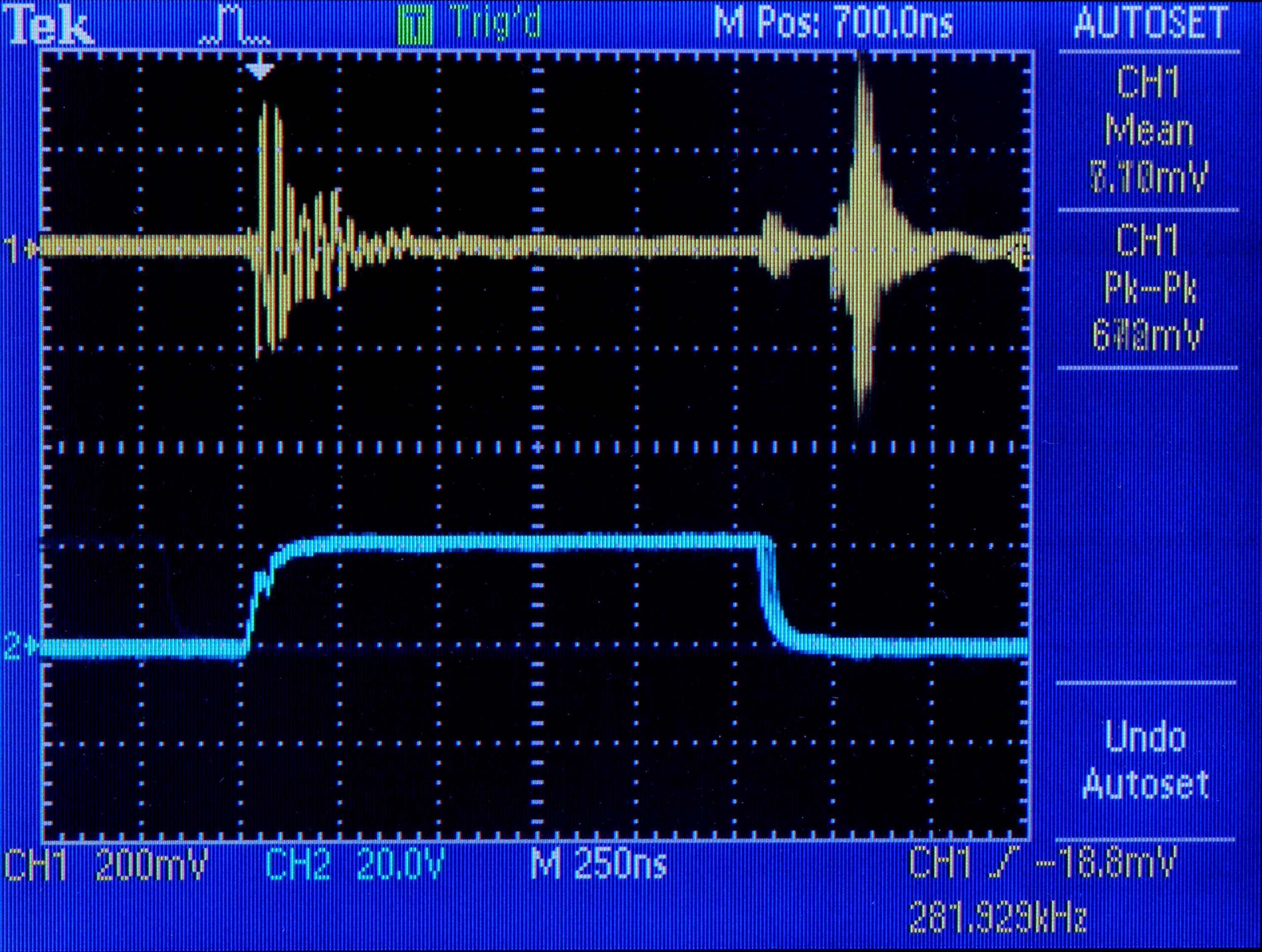
I traced the ring to lots of different points in the circuit — back up toward the transformer, all over the place. Finally out of exasperation I put the scope probe on the same ground point I was clamped to, more as a joke on myself than anything — and saw the ringing there too, clear as day.
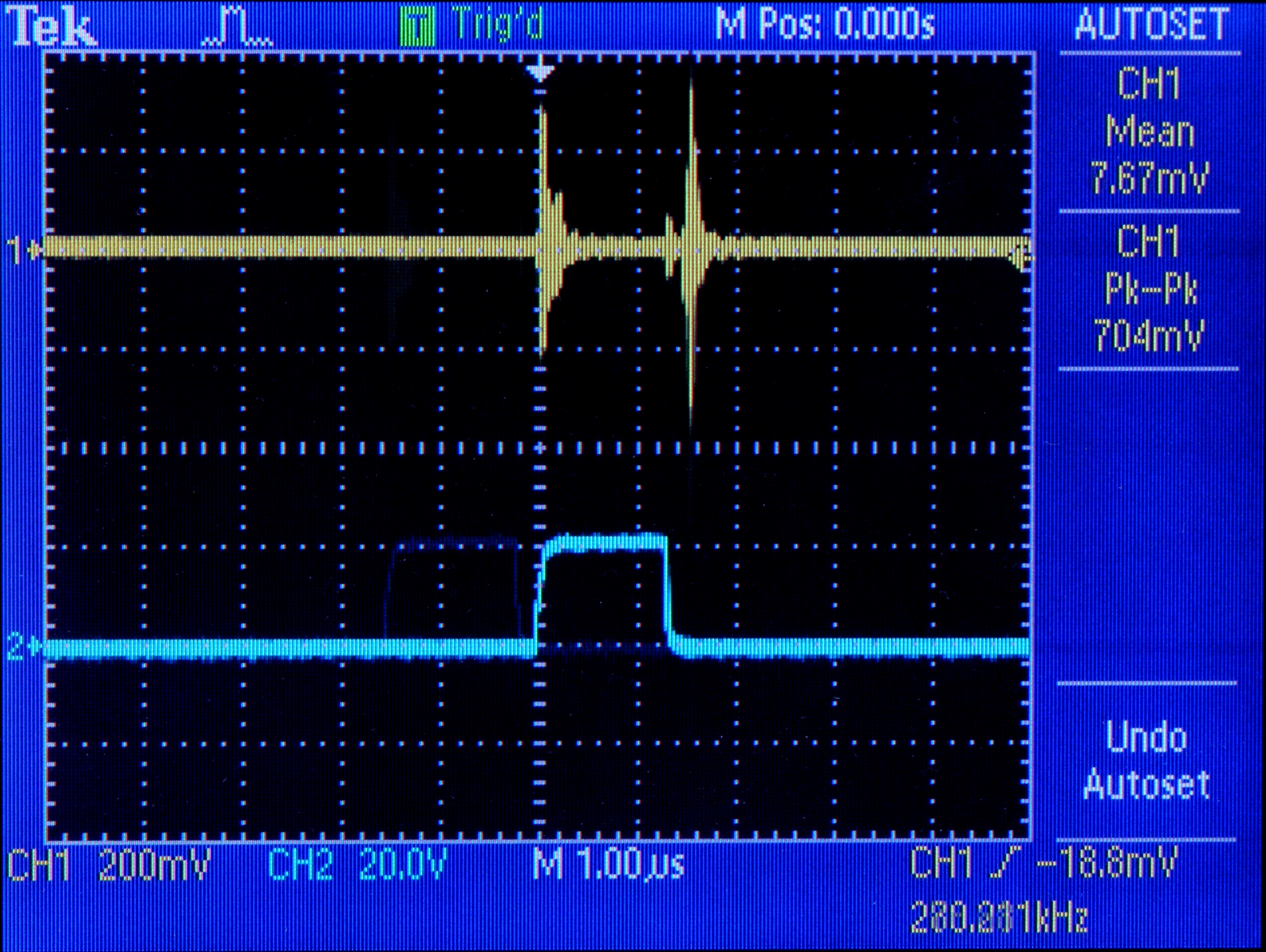
Trace 2 is the FET gate drive; trace 1 is noise on the ground plane. There’s almost a volt of spike on the ground plane every time the FET switches on and off. I hadn’t been seeing noise everywhere else throughout the circuit; I’d been seeing noise as measured between each point and noisy ground.
(Okay, how can a scope register a signal between its probe and its ground when they’re connected to the same point? I assume its ground connection is capacitor-filtered and its probe obviously is not. That could mean that I wasn’t just seeing dirty ground everywhere and there really is noise throughout the circuit — but I know there shouldn’t be that kind of noise on the ground plane, and I want to eliminate that before worrying too hard about the rest.)
Here’s the same thing zoomed in,
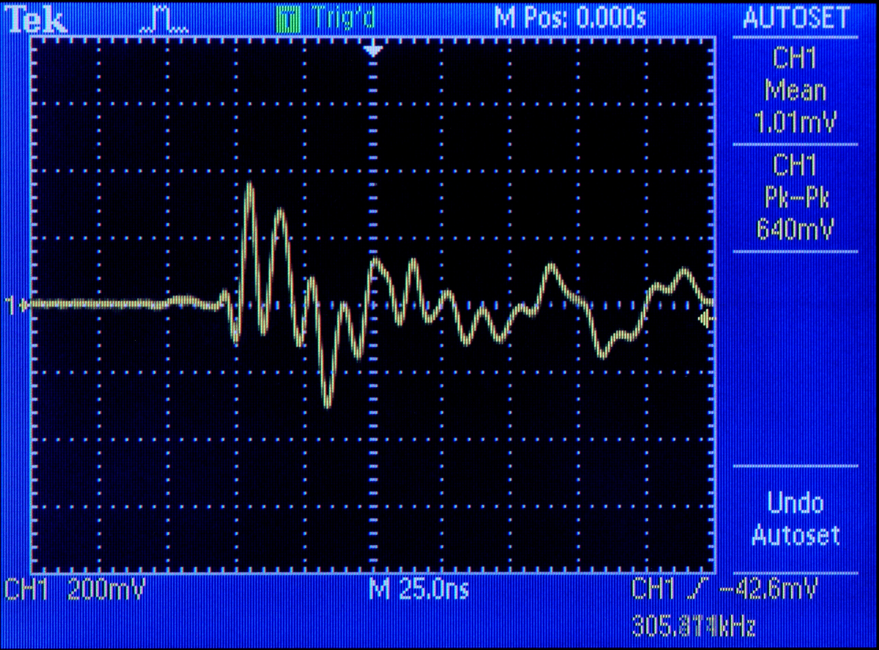
and a closeup of just the first ringing.
To add insult to injury, the only connection between the primary and secondary sides of the circuit besides the transformer is C24, which capacitively couples the two ground planes. (I don’t fully understand why.) And C24 couples the noise into the secondary side’s ground slick as can be, where it appears on the power going to the mixer. Crap.
My immediate intuition was that the big 100uF 400V capacitor across the power supply was aging and no longer able to respond to transients as fast as 10MHz. When the FET switches on, the circuit makes almost a dead short between +170V and ground through the transformer; it seems natural that ringing during the transistions should appear on both the power and ground lines, and C18 is the only thing that would really be in a position to catch it.
It also occurred to me that maybe this ringing has been there from day one, and either the engineers didn’t notice or didn’t care. But that’s not a happy thought; and as I don’t have access to an identical mixer to see how it operates, I’ll just push that back to the dark, cynical recesses of my mind.
C18 has a lot of capacitance; but it’s so big, it might not be able to respond quickly enough to very fast spikes. This, I assume, is why C2 is paralled with C1 — so perhaps a smaller-valued capacitor in parallel with C18 would help kill the 10MHz ringing. (Perhaps a brand new replacement for C18 would do the job also — but if that fixed it, then in a few years the new capacitor would have aged enough to regain the same problem. Better to fix by design than by manufacturing.)
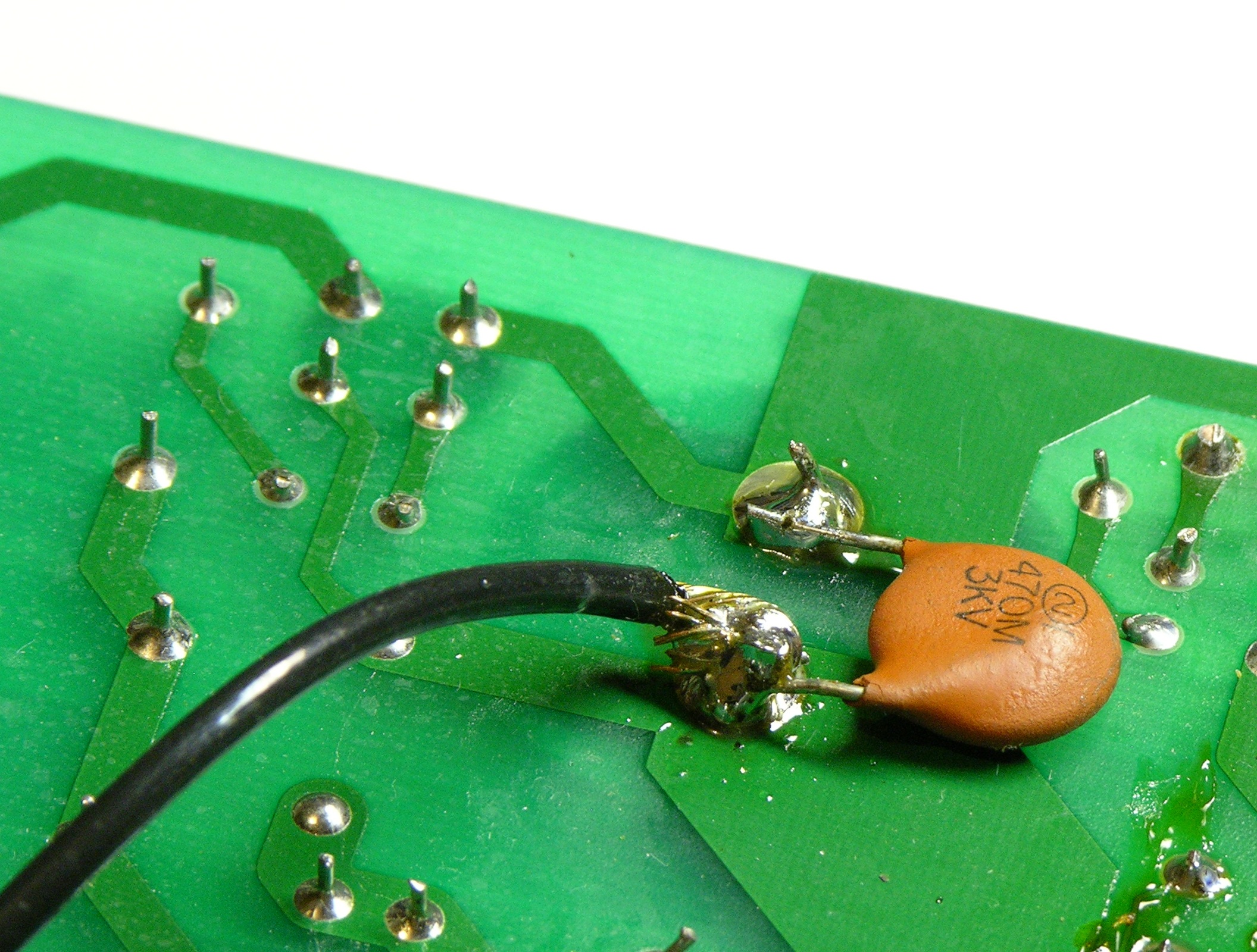
I found a 330nF capacitor that looked like I could trust it with 170V plus spikes and soldered it on in parallel with C18, and it doesn’t appear to have made any difference. Also tried 4.7nF, 150pF, and 47pF (shown here), all with no apparent change to the ringing.
I don’t have many ideas left, and I’m really not happy leaving the power supply the way it is. Maybe someone out there with more design or repair experience has a suggestion? Maybe the scope is playing tricks on me and someone can explain how?
Julian — yuck! That schematic export really is hard to read.
You have the two swapped — D5 is the EGP10G and vice versa, and the part identifier and model sandwich each part. But I think you have the right diode type for the Zener, at least as far as I can read it. I’m not at the same place right now as the computer with the original schematic on it and I have a pending blog post on synchronization software I’m about to try for keeping my files identical across multiple machines but for the moment I’m not able to check.
Since the one in your power supply is broken anyway, you could clip the leads (makes it even easier to desolder later) and compare with a magnifying glass to what I wrote down.
Ah, I found my online order and I bought a 1N5378B. In fact, apparently I bought ten of them (minimum order). So if you can’t find them locally and you’re not in a hurry, I can mail you a couple.
Hooray, some success for me!
In the end the switching IC wasnt starting, most likley because C1 and C8 were bad, although they measured ok on a cheap meter. I replaced these three. The Fet was also blown, and kept D6 blowing (with a good FET) as the switching IC would try to start continuously and cause surges of power through the transformer. Replacing all of these components got everything working nicely again.
I ordered a replacement switching IC from TI so ended up building a mirror circuit to figure out what made the thing work. Ive ended up testing just about every component in the circuit now. Once the switching was happening again with a new IC, C1, C8, the FET and diode were replaced it worked as it should.
I measured the supply loaded and unloaded for curiosity:
+/-22V and 53V unloaded
+/-16.5V and 48V when drawing ~4W.
After powering up the mixer board some of the channels appear damaged with some humming and the headphone driver is damaged also, it must be outputting DC as it nearly burnt my ear haha
I’m still wondering what caused all this. Perhaps a power surge of some kind…
Forgot to add: Many thanks to everyone for the help and Keith for the schematics!!
Congratulations Matt
I’m having a little trouble finding a D5 replacement (EGP10G 400V 1A) – various UK sites list it as discontinued. I found the following which by comparison to the EGP10G datasheet I found SEEMS to be very similar. I’ve no idea how exact these things have to match?
http://uk.farnell.com/vishay-general-semiconductor/uf4004/diode-fast-1a-400v/dp/9551654?in_merch=true&MER=i-9b10-00001422
The same goes for the capacitors – similar but not exactly right in that they only go to 85C not the 105 recommended
http://uk.farnell.com/jsp/search/productdetail.jsp?sku=1365157
The zener diode I think is exactly the right one, but here’s a link for the sake of completeness:
http://uk.farnell.com/jsp/search/productdetail.jsp?sku=9558349
Any chance you could have a look and check these for me Keith? Will they be ok?
Also they have a standard shipping charge of £15.95 which is crazy for £4 worth of components. Can anyone suggest some other stuff that might prove useful I might as well add to the order? Maybe some other components that have a high chance of being faulty? Or should I order more of each to be on the safe side? And then anything else? I have an “extra hand” clamp, soldering iron, solder – Solder wick is already on the list . . . anything else you’d consider essential or just well worth having?
cheers and thanks again!
Julian, I’ll go through the rest of your questions later when I have a little more time, but I can answer one now — you absolutely want to find capacitors rated for 105°C. You can see by the scorch marks that it gets warm in there, and capacitor failure from baked electrolyte is very possibly the root cause of everything else that’s wrong. You really don’t want to shorten their life even further by going with a lower temperature rating.
Sorry to bear bad news on this, but I’m pretty insistent on that point.
Any idea what it costs to ship from the US to UK? I already have spare Zeners and capacitors and I could get D5 (or a workalike) in an order I’m about to place and ship them to you at cost. That might save you on their crazy shipping charge and would definitely be worth it if you can’t find the capacitors locally.
I think I found the right capacitor:
http://uk.farnell.com/illinois-capacitor/476kxm063m/aluminum-electrolytic-capacitor/dp/1168033
As it turns out the high shipping cost is because they have to get the capacitors and one of the diodes from their warehouse in the USA!
I’ve no idea exactly how much the USA to UK shipping would be – but I guesstimated that the components and a small jiffy bag definitely wouldn’t weigh more than 200g (the whole PSU board weighs 146g!) and so if I was sending from the UK to the USA then it would be around £3.00 or approx $5 – that’s airmail for a small packet according to the Royal Mail website. Presumably it’ll be in the same ball park coming the other way?
http://www.royalmail.com/portal/rm/content1?mediaId=53800712&catId=400036
Of course actually sending the PSU board would be more because once it gets beyond a certain thickness they charge more regardless of weight – but a few components shouldn’t be a problem . . .
cheers
Well I heard back from Soundcraft that the replacement boards are available but cost around £50 + postage – that’s a long way towards a new mixer of similar quality so I won’t be buying one!
Keith any more thoughts on being able to send the components? I’d be very happy to send you some cash upfront?
I think you should have my email?
cheers
Julian — I haven’t placed my electronics order yet and it may turn out to be a couple of weeks while I work out a couple of things. That means probably a month for you to wait for the parts to arrive to me and then turn around and ship them to you.
If you can live with that, then hold tight and I’ll get in touch when my order is on the way to get your shipping address. If that timeframe is too long for you, I understand; but I’m really not sure I can push it much shorter right now.
What do you think?
Keith – Many thanks for the kind offer, but I’d like to get this fixed soonish if possible. It’s taken some searching but I’ve managed (I hope!) to get the right components here without anything needing to be sent from the US. Should be here in a couple of days and will post again when I have more news!
cheers
Julian — I don’t blame you; I’d probably be eager to get it fixed too. I’m sorry it didn’t work well for me to get the last part you needed, and I hope your repair succeeds!
Well sad to say having swapped out the two diodes and the two capacitors I still get the fast ticking noise from somewhere around the yellow thing with the copper band just right and bottom of centre on the pic at the top of this page. I’ve no idea what to do next? It’s entirely possible that I haven’t soldered the new parts properly, given this is my first ever attempt at soldering components onto a board. However with the identical ticking noise maybe it’s possible that they are replaced properly and the fault is somewhere else?
No idea what to do next? Replace the components again? I have lots of spares!
cheers
Julian
Julian, with the power disconnected and after testing that the voltage on the large capacitor is discharged, check the two diodes again. If they’re burned up again, there’s something else very wrong and you shouldn’t bother to replace them again until that’s figured out. If they’re okay now, then we start looking further.
Would you feel confident in your ability to measure parts of the circuit with the power on and without hurting yourself or the board? I don’t want to persuade you to do it if you don’t want to; rather, I don’t even want to make suggestions about what to check unless you say that you’re comfortable trying.
Keith – I’ll check the diodes again when I have some free time. I’ve had to pack it all away as we have guests staying. With my present knowledge I’m not sure about avoiding hurting the board. I’m pretty confident I wouldn’t do anything that would hurt me – but that’s just based on my avoiding putting “me” in the circuit!
Unless there are some straightforward “do’s and don’ts” I can apply I suspect I’m getting out of my depth with regard to further testing . . . that said I’m keen to learn, but appreciate that what I need to learn may not be possible without signing up for a course of some kind.
cheers
Hi Keith,
thanx for the lengthy explanation. I’ve got a Spirit ES that is blown. In my power supply it’s very obvious that D6 is damaged (the circuit board it singed). So I’m going to replace D6, C1, C8, D2 and D5 which all look like they would be burned out. I’m not even going to bother measuring them (since I don’t really know how to do that… probably not hard, I’ll take the time later to figure it out).
The board is not mine, but the guys told me that there was some high pitched noise. I hope that I don’t get any other issues with it once all the parts are replaced. If so, I will have to do some more studying.
Thanx very much for all your info though.
Cheers, Hans
Great Page
My Fault was the SMPSU was pumping. I changed the caps on the output side and then the caps on the primary side, still no joy.
Went onto the web to find a drawing or information. Found this page !!!
It was D6 (short), great trick with the neon. I have used light bulbs as loads before. £ 1.26 for a pack of 5 from RS.
Thanks
Peter
What a wonderful site – thank you. As an old sound engineer I’ve messed about for years building and trying to repair kit; and I’ve come across some very helpful sites, but this one certainly takes the biscuit (or cookie in the US!).
Some time ago a musician friend asked about getting a cheap secondhand desk and we fell across an E6 which seemed to be an absolute bargain albeit channel 1 was dead. Turned out IC700 (TL074C) had vaporised pins 4 and 11 along with some bits of track on the other side – sounds awfully like Andy’s experience. I drilled through the board and managed to tack a couple of fine wires onto the remains of the legs which were just showing on the ic and voom! for once it did work, although with a little bit of hum at full gain (Matt August 2009), which I failed to trace. A few months down the line the desk dies, open it up and it’s a dreaded switch mode. Quick search online and up pops this amazing site – salvation.
The usual scorched area, C! & C8 are both gone and D2, D5 and D6 are short. the 1N5378B is available, but the EGP10G (BYD73G in the Technical Manual) does not appear to be. I’ve also checked the Digi-Key UK site and they only appear to be available in minimum quantities of 25,000! with a ship date of June. In fact the US site now seems to be listing them as non-stock with large minimum quantities as well. In the meantime I will order the UF4004 suggested by Julian which seems to more or less matches as far as I can see apart from power dissipation of 2.08W instead of 2.5W. Because of this I wondered if, from a reliability point of view, it would be better to go up to a higher power one like a MR854 which is the best equivalent I can find. I would be grateful for your thoughts on this.
Once again many thanks for this site.
Angus, glad this was useful to you!
I’m not an engineer and I’m not qualified to answer the question about substituting D5, so you need to use your own best judgement. However, I can tell you that I would simply try one and see how long it lasts. If it blows again, at least you know what to do differently next time — and I bet if you treat the capacitors nicely (get them up off the PCB) the whole thing will last longer.
This is part of the inductive kickback suppression circuit, so I expect power-handling is going to be the only critical characteristic of D5. If it’s easy, maybe go for the higher-power diode.
My advice to those who wish to remain faithful to the original switching power supply is to add some safety feature to the output. I suggest that each of the 3 rails (+15, -15 and +48v) be fed to the mixer via fuses of two 1amp and a 200ma respectively. On the mixer side of these fuses I suggest a zener diode on each rail, two of 20v and and one of 60v connected to the rail and 0v.
Personally, I have gone down the route of converting to a linear power supply as per the previous Soundcraft series Spirit Folio Si. It is a bit lossier but reliable and pretty much noise free. Good luck All, and may your parasitic oscillations go with you
Update
Replaced C!, C8, D6, D2 and D5 (EGP10G – found a supplier that had some). Powered up unloaded to an immediate smell of something cooking – D6 red hot. Tried loaded with the same result. A few very brief power ups seemed to produce roughly the correct output volts before D6 went short again. I guess that from what Matt writes that means the FET and control IC are next for replacing, but with his damage to the mixer board and Andy’s words of wisdom I honestly wonder if common sense dictates cutting one’s losses and going for a conventional supply – would it be too much to hope that someone might have a design to hand or know where one might be available!? – I’ve searched about and can’t find anything, not even a ready made one.
Thanks again,
Angus.
I have problems with a Soundcraft Spirt E-12 PSU. It is burning up D-6 but will power up the board for about 3 minutes. Checked C1 and C8 and looks like Tx1 has got pretty hot. I am lost, and Soundcraft wants $180 for a nw board
Hi,
i Have one mixer with this very same supply.
i have problem with C8! It’s too HOT!
What should i do?
i Already replaced C1 and C8
Mixer is woirking at 220v
A fairly simple linear PSU can be constructed using a 15-0-15 transformer, even deriving the higher voltage for the mics’ phantom supply and their input stages. It is cunning and works well. I will draw it out properly.
Keith, how could I up-load a diagram or jpg please? – Ta.
With the cost of components (or rather postage) mounting, it was decided that a new PSU from Soundcraft was the not that much more expensive answer. Interestingly this has a few mods, principally a fairly sizeable twisted vane heatsink bolted on to the FET. C1 and C8 are still 85°C though. There is also an insulation sheet attached underneath which the older series desk like this did not have. Another two were supplied and. I guess one of these is to stop the top break-off section shorting on the metal plate which covers the PSU, after it drops down when the cover is removed for fault finding – owners of early model desk BEWARE!. I would have preferred to build a linear, but was defeated by the 48V conundrum – I would love to see the cunning plan if that were possible, not least for when this new supply decides to go phut.
This time when it expired it blew IC8 and fried R37 & 38. Fuses and zeners are now fitted, but I went with Andy’s earlier recommendation of 18v and 51v zeners, and erred on the side of caution with 400ma and 100ma fuses.
Once more with thanks,
Angus.
I replaced d6, c1, c8, but then c-18 smoked, replaced c-18 and d6 again the board powered up with all functions working including the 48 volt. Ran functional check with mics and line inputs and everything worked fine. I left it powered up for 6 hours and no smoke. I still don’t trust this thing. Russ
Andy, I don’t know of a way to upload a diagram into the comments. The best option I know of will be to use an external image host (Flickr, if you don’t have something else available) and link to it from here.
I’d appreciate it if when you post that, you’d add a note to the effect that I have not reviewed, analyzed, or endorsed the design. It’s completely fine that you’re offering an alternate circuit, but I can’t accept liability for people trying it.
Hello thanks for this informative site… My spirit e-6 has burnt D3, D5, D6, C8, R10, R11. As well as IC6 on the main board… does this mean I’m done? or is there hope for me? I have done smaller electronics repairs in the past, I would like to conquer this too
Ryan, wow, that’s quite a list. When you say they’re burnt, are you just referring to discoloration on the PC board or the components, or have you measured them out of circuit (or with a high degree of expertise and confidence in circuit)?
D6 is bloated and cracked, and IC6 has in essence exploded… the rest are discolored but have not lost form…. my main concern is the ability to source the ic6 and to determine what else is further along that circuit, hoping no more damage is done, just through a quick visual analyses im assuming it’s related to phantom power(quick being about 10 seconds), I don’t have access to a scope yet and can’t find one of the probes for my multimeter so further testing beyond visual inspection is not possible yet. thanks for the quick response!
Rather I should say… my concern is whether IC6 is source able and whether it can be repaired… as I see very little reason to concern myself with the power supply if the main board is hopelessly shot. I came into this board in this condition, and i feel when the ps started to go/ or went… it was still left on for a considerable period of time(days or weeks possibly). The discolourations of the board and components in there is notably worse then in your photographs.
Most of those same components had blown for me too. I would replace as many things as you can, most of the parts are cheap. The power supply can be powered up unconnected to test if it is working correctly once those bits are replaced.
My journey replacing surface mount components on the main mixer board continues… I had to order a bunch of DIP8 opamps to replace on the main board. They are mostly TL072, common as you can get. Just about any dual opamp will do as a replacement. Replacing them without damaging anything else is the real trick…
Ryan, I can’t find IC6 in my photos; can you tell what it is?
If it is one of the TL072s, I’d stick with an exact (or close) replacement — those are low-noise op-amps, so (for example) I wouldn’t sub a TL082.
If you look on the main board directly beneath the phantom power switch and the headphone jack there are 3 small 8 pin IC’s, the furthest left is IC6, the two on the right seem to be the same IC, and are marked N5532 29M C820. There also appears to be what I had believed to be the texas instruments logo, but now am not so sure, as I’ve been having a difficult time locating any info based on the markings on the other 2. If you have any idea of what these are or suitable replacements, hints or anything it would be much appreciated!
Of course after I post I narrow my search terms and find plenty of references. My apologies…. I guess my next step is to see if i can locate some that don”t need to be ordered in huge quantity. Then on to PS.? Or does anyone think the location of that blown IC could indicate severe damage to the board…..
Funnily enough, one of those headphone IC’s blew on my mixer board too, perhaps the ne5532 is more sensitive to the tl072′s used elsewhere (although some of those blew on mine too).
I would recommend fixing your power supply board first, then power up the mixer. You can work out how many channels have problems then
I had one dwad 5532 and i replace it. All works good.
NE5532 is very cheap IC i bought 50 psc and TL072 50pcs ..
I replaced Master Output ICs (5532) also removed Master sliders and brick it directly.
Also, about supply, replaced all capacitors and much stronger puted. Now muck less heath.
ah this gives me hope then, so that particular opamp is dealing with the headphones then? I was initially afraid that one being blown was a death knell, so this is turning into quite a fun little project. Yes knowing this now I will begin to piece together a list of parts i’ll need for the PS.
An update… replace D6 C1 C8…. in your words “And voom! The power supply … er, still didn’t work. Durn.”. Went back to testing and realized somehow I had missed that D3 was short. I removed it and gave it a quick test power up, and I got my first sign of life… the click, click, click, lights on, lights off, syndrome. (Note if you care about your board do not turn on while missing components, Mine was basically free and If I fix it great, but if not I’m not too bummed)
I’m having trouble reading the writing on D3 though. I think a shoddy print combined with heat has made mine almost illegible, can anyone identify this component for me?
@Ryan
D3 looks to be SF1600… (that is all I can see and I didn’t want to remove it.)
My board has “the click, click, click, lights on, lights off, syndrome.” and the heat marks on R3 & R4, and it looks like D6 tested bad (still on board, so not sure yet). I will be checking local repair shops in hopes for parts, and hopefully I can get mine fixed for the dance it is required for in 5 days.
WOW! I appreciate all the work that has gone into exploring this problem. I have 2 radio stations that use these boards (desks?). I like them a lot because of the many stereo channels, low noise and low price. Presently 4 boards in service, but one just dropped dead, with a thump-thump-thump. Rather than fighting with these switching power supplies, I am willing to use an outboard linear supply. Would someone please tell me, what are the required buss voltages?
Thanks VERY much,
Randy
Oops… Read more thoroughly and found the voltages: -15 and +15. Not going to bother with the +48. Found two wall-wart 15 VDC supplies. $18.00, US. Let’s see what happens…
Randy
Randy, You will need the +48VDC rail for any of the mic channels – it is used within the mic preamp, not just for phantom power. Without the +48V all but the mic channels will work.
Hi Andy, Thanks for that. It certainly explains why the mic channels don’t work, except for a slight hum when the faders were advanced. Both L & R outputs and all line inputs are good.
Does anyone here want to rebuild my supply, for a reasonable cost??? Please?
It looks like good ol’ D6, along with D4 & D7 took the hit, along with whatever else. Also lost one channel of the headphone amp, but can live without it. I can’t see well enough to replace those itty-bitty ICs… A cruel joke that our eyes get weaker as the components get smaller.
Thanks, Randy
Randy, what’s a reasonable cost for the rebuild?
I would enjoy doing the work but don’t have a mixer to test the result in-circuit (I don’t feel good about borrowing one from work as a guinea pig for a personal repair), so we’d have to talk about whether you wanted to ship the whole mixer or take our chances that a dummy load I could contrive would adequately test the supply.
You should at least quote a replacement board from the factory for a comparison price (and maybe it’s low enough that repair labor can’t beat it).
For those of you who would like to build a linear PSU as a replacement for the switched mode standard, I have actually got round to drawing one up and now have up-loaded the diagram to here http://www.mediafire.com/?9t9335bi37n0q It is a Word Doc with the diagram therein.
Please let me know if I have made any howling error(s).
Andy~
Almost forgot to mention, and this is important. The Diagram available at http://www.mediafire.com/?9t9335bi37n0q is not reviewed, analysed or endorsed by by Keith Neufeld. I cannot take responsibility for those who use it and do not endorse the design. I supply the diagram in good faith.
Be sure to provide heat sinks for the voltage regulators and note that the regulator bodied mist remain electrically isolated from each other.
Andy~
Hi All,
I am amazed at the info on this blog. I would like some idea of what might need fixing on my Spirit e12. Bought is used and need to get it working. Not working- phantom power light, all 12 mic inputs, all 12 line inputs. Working all 12 inserts.
on the PSU board everything looks ok except C14 which has a swollen top. Minor heat marks underneath R13. My R3,R4, and R13 have longer legs with ceramic covers on them.
Sam
I was about to make a plea to Andy asking if he could possibly find a way of publishing his cunning plan, when lo and behold it appears – excellent, with readily available components and easy to build to boot.
Thanks very much indeed.
I have the circuit diagram. If anyone needs it mail me at
farquhar at inbox dot com
Hi
Firstly many thanks for the lengthy, detailed and interesting article. you can add me to the list of people with blown Spirit PSUs (E12 here).
Ive got someone helping me out with this, but im reading it for my own interest and benefit. according to the expert, my board is blown beyond repair. its very brown!
http://www.paradigmx.com/gfx/Mixer/mixer06.jpg
http://www.paradigmx.com/gfx/Mixer/mixer03.jpg
if you are interested.
I with guidance from my friend intend to build a linear supply. As i never use mics, ,i was thinking of ommitting the 48V. But a comment from andy Miles above states ‘Randy, You will need the +48VDC rail for any of the mic channels – it is used within the mic preamp, not just for phantom power. Without the +48V all but the mic channels will work.’
Now does this mean every channel but the stereo ins? or only if i use the mic (XLR) inputs. I only use the jacks with line inputs.
Many thanks ben.
Ben, I’m not personally familiar with how the 48VDC rail might be used in the Mic channels. Perhaps Andy Miles will return and remark.
You board, by the way, looks reparable to (or by) me.