A little while back I bought a couple of used Axis 2100 network cameras, intending to use them at home (driveway cam? front yard cam?) to replace my lousy Linksys WVC54GC. The Linksys’s video stream is viewable only in Internet Explorer or with VLC; the Axis (although older) streams motion JPEGs that can be viewed with just about anything, provides still JPEGs, and has FTP server upload capabilities to update a statically-served image on a web server.
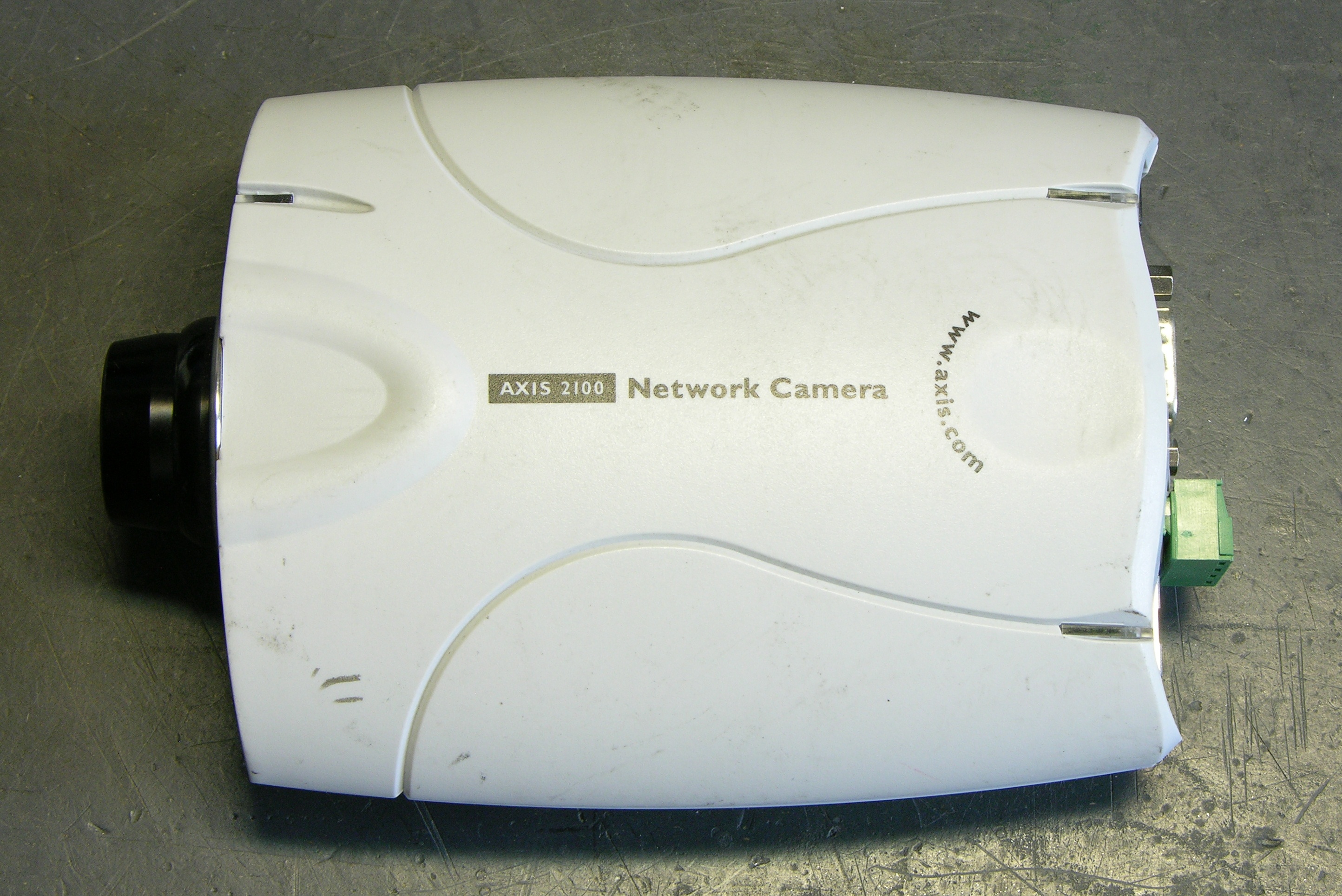
Power Over Ethernet and Power Splitters
Having got them, I decided I’d like to play with one at work, installing it in our 3rd-floor bay window overlooking campus, so those of us with windowless offices can get a little sunshine in our lives. That would be easiest if we didn’t have to run both ethernet and power to the camera separately, so I started reading up on the camera’s power capabilities.
Power over Ethernet (PoE) is a standard for delivering 48VDC over an ethernet cable — depending on the implementation, possibly on the same pairs used for data, possibly on the spare pairs. The data pairs use differential signaling (the difference between TX+ and TX- is the signal, like balanced audio, as opposed to a single signal referenced to ground), so the DC power can be provided on the two wires of one pair and grounded on the two wires of the other pair (similar to the way phantom power is provided on balanced audio cable).
The product web page almost intimates that the camera supports PoE:
- Access to a power outlet not needed with use of Power over LAN Midspan and Active Splitter from Axis
- No need for power outlets and electrical cabling using Power over Ethernet products
But in fact the camera doesn’t operate when hooked to a PoE connection. Additionally, another Axis page lists a “PoE splitter” for the camera, which strongly suggests that power may be delivered over the ethernet cable by standards-based or non-standards-based means, but must be split externally before entering the camera.
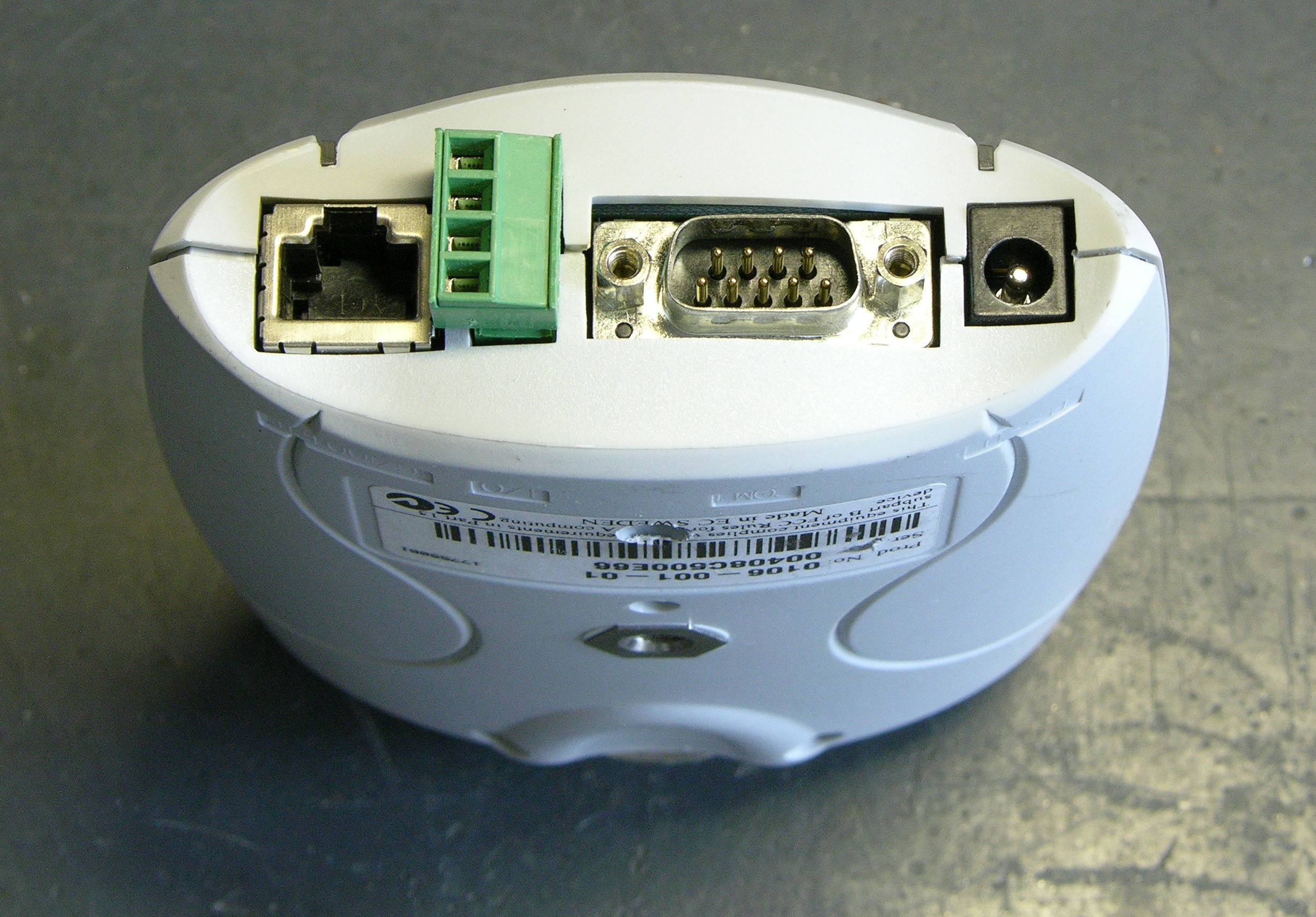
Still, pp 59 and 62 of the users guide show intriguing connections among the I/O port, the power connector, a bridge rectifier, and a switching power supply; and p 65 lists the power supply as accepting 9-15VAC or 9-15VDC, which is kind of interesting. Even though the unit clearly doesn’t function on PoE, I thought it was worth opening up to see whether it would accept non-standards-based power on the ethernet port.
By the way, recognize that green thing?
Going In
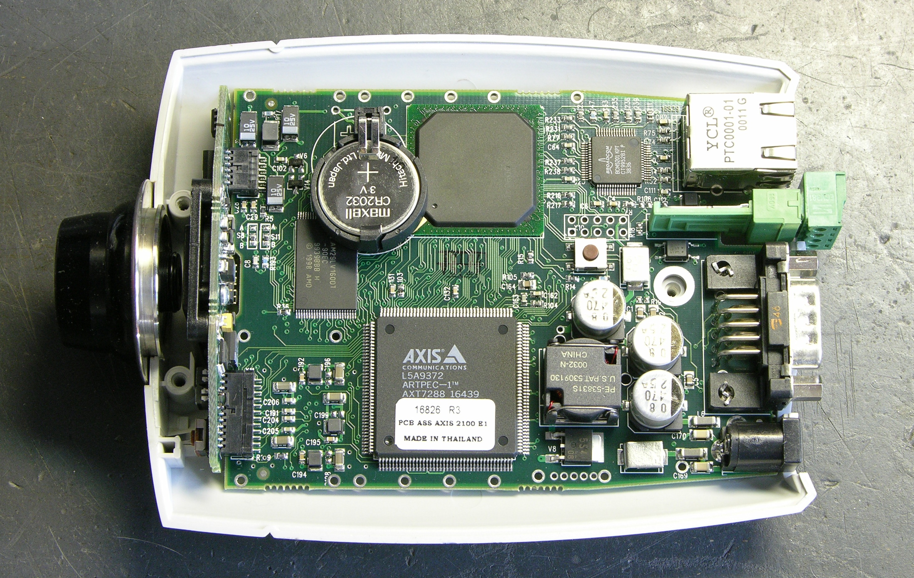
Here’s the camera with the bottom of the case lifted off. Note that the top of the circuit board faces the bottom of the enclosure.
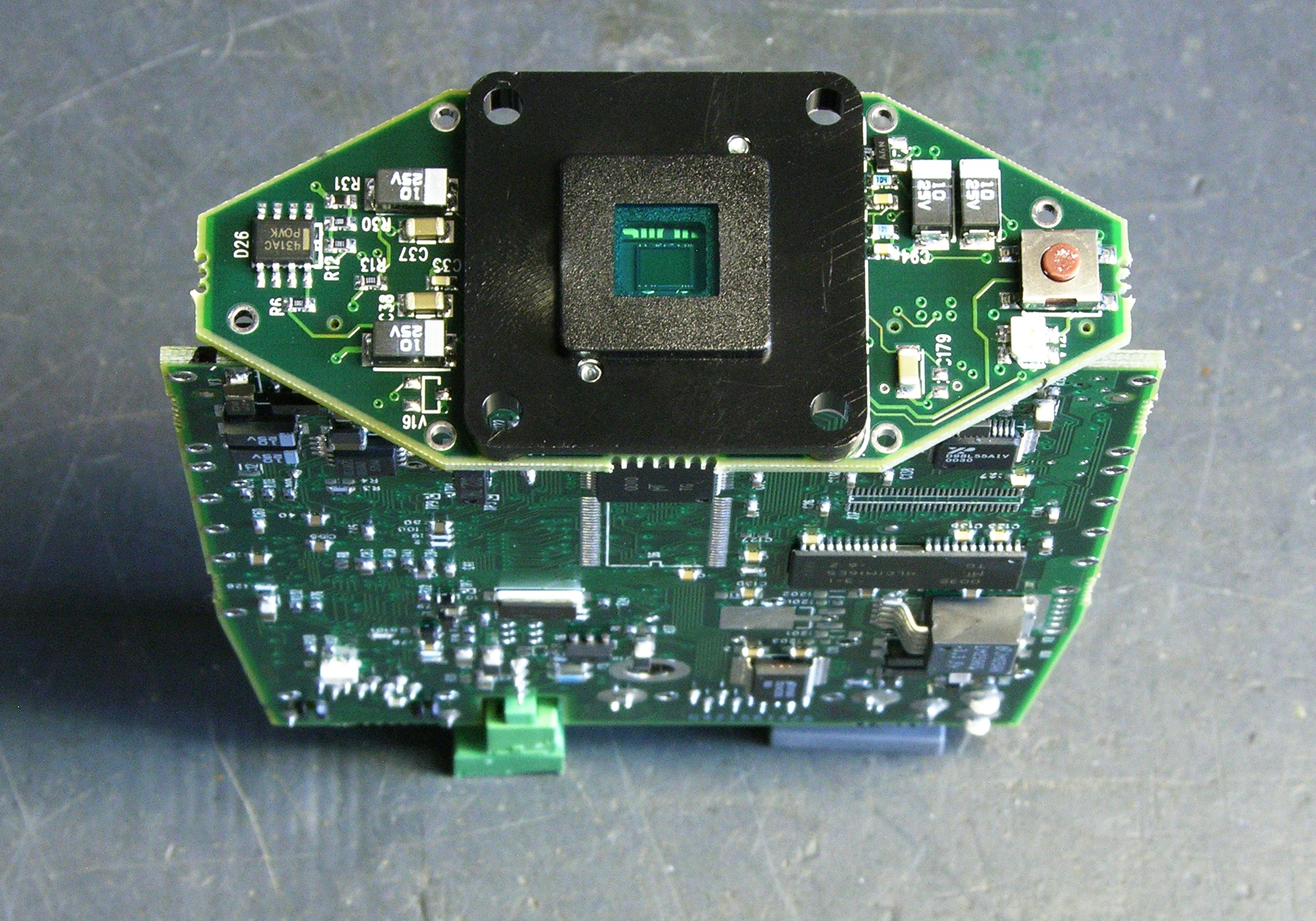
The CCD is on a separate PCB stuck onto the end of the main board.
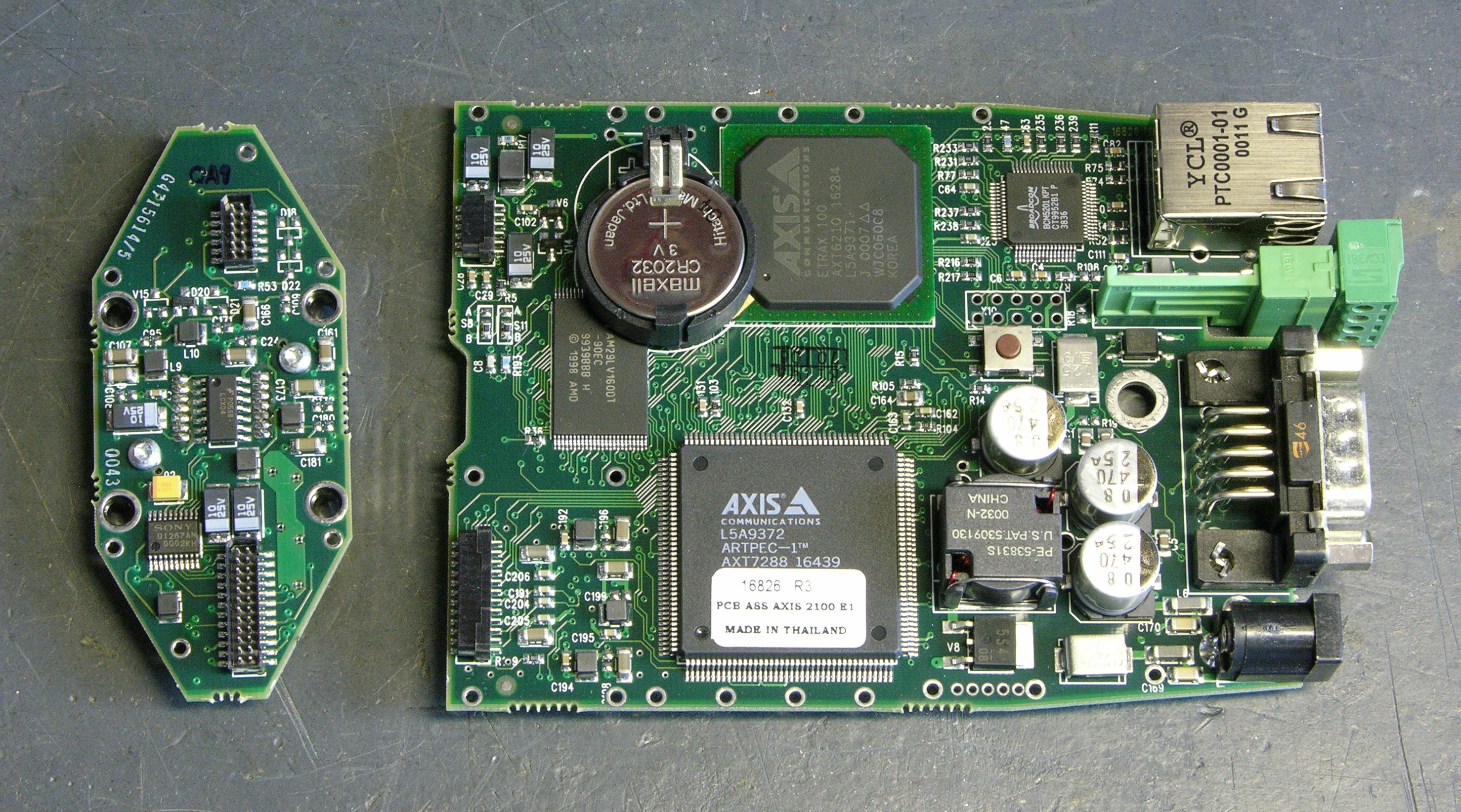
Another view of the top side of the board with the CCD board separated.
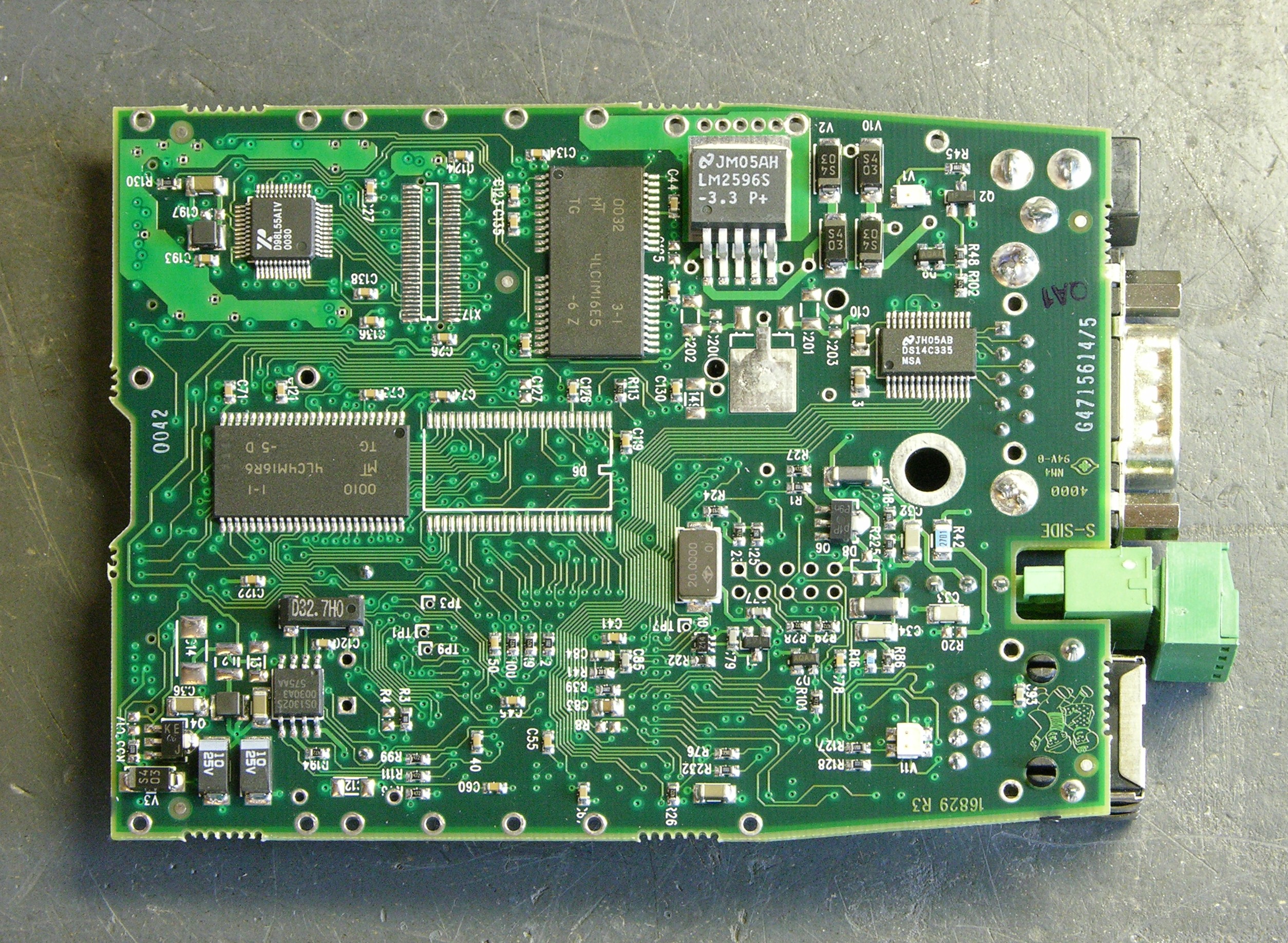
And the bottom of the board (facing the top of the enclosure).
Continuity
I started by trying to trace connectivity from the power jack to the unit’s ground, not remembering that the camera accepts AC input. I got no continuity there, as my tester doesn’t indicate continuity through diodes. After noticing the bridge rectifier (last photo above, just to the left of the upper right corner), I realized my error and was able to trace ground from the rectifier output throughout the unit.
Next I traced from the power jack to the I/O connector and confirmed the connections shown in the user guide — you can provide or draw rectified and filtered but unregulated DC power on the I/O connector.
Feeling bold from my discoveries, I checked continuity to the ethernet jack. I got DC continuity between ground and the center pins 4-5, but no other connectivity. Bah! No non-standards power on ethernet for me.
Hm, but I also hadn’t successfully traced V+ from the rectifier throughout the unit. I figured I needed to pick it up from the other side of the LM2596 voltage regulator — which turned out to be a switching step-down regulator.
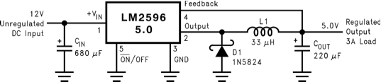
Pin 4 is the feedback that connects to the filtered, regulated output — and indeed, it connects to the V+ power supply pins of all kinds of things throughout the circuit. Cool; progress! Maybe the regulated DC voltage connects to the ethernet jack???
Mm hm, it sure does. I get DC continuity with .4-.5Ω resistance from the V+ rail to ethernet pins 1 and 2 (TX+ and TX-), DC continuity with .2Ω resistance to pin 3 (RX+), and no connection to any other pin.
So?
Although the datasheet’s application circuit above shows the 5V step-down regulator, the camera actually uses the LM2596S-3.3 for 3.3V power. That this appears on both TX pins of the ethernet port suggests that I could provide DC power on pins 1-2 and ground on 4-5.
But it would have to be regulated 3.3VDC, which (1) isn’t standards-based PoE and (2) isn’t going to travel well over 100+’ of cable. This suggests that a non-standards-based switch-end power injector directly in through the camera’s ethernet isn’t going to work well.
More plausible: Build a PoE-attached power supply with a 48V-3.3V step-down converter and hang it off the back of the camera. At first I thought that doing PoE would require a dedicated PoE chip to do the negotiation, but all that’s needed is a 25kΩ resistor across the powered pairs. So it really would be feasible to do, without a special chip just for the PoE.
However, if the solution is going to require external PoE down-conversion anyway, why bother going all the way down to the regulated 3.3V? Why not go 48V-12V and come in the regular power jack, which also eliminates any risk of making the LM2596 unhappy by feeding power into its output? (Its block diagram looks like that shouldn’t be a problem, but I don’t know enough to be certain.)
If using an external down-converter anyway, the only drawback I can see of splitting the power out to feed the the power jack separately rather than the ethernet is the requirement for an extra connector.
Or the Simple Way
Regardless, I don’t really want to have to build an external step-down regulator just to get the cameras working. So for now, I’m more likely to build simple cable splitters to inject 12V onto unused pairs at the switch end and split it out to the power jack at the camera end.
That’s interesting, but why not delete the entire thing.. you come to no useful conclusion and merely provide a glimpse of non-hope in the end. Shame on you for doing a web area for nothing, to no end, and provide nothing useful beyond.. a blog.
Jf, I doubt from the tone of your comment that you’ll check for a reply, but I think your question deserves a response anyway.
First, I see from my server logs that you found my blog post by searching Google for “Axis 2100 power over ethernet.” I would suggest that if you read my post carefully, you gained a valuable piece of information that took you less time to find, thanks to the benefit of my research, than it took me — that the camera does not directly support PoE. If I saved you half an hour of searching, surely your time was worth something, as was the (albeit unwanted) negative answer.
Second, given the phrasing of your Google query, I’ll speculate that you’re more of a network professional than an electronics hobbyist. If that’s accurate, you can be forgiven for missing some of the value of this post to another hobbyist — a walkthrough of how to approach investigating an electronics question to which you don’t yet have the answer.
I know plenty of bright people who wouldn’t know how to begin answering this type of question on their own — or more to the point, simply lack the belief that they could do it. By talking through the steps, I hope to show that the process is not as daunting as it may appear at first glance. Tracing connections with a continuity checker and looking up component datasheets are simple but very valuable activities that can lead (as in this case) to a confirmation of what was previously only a suspicion.
I’d welcome additional comments from regular readers whether this type of post is of interest to you or not.
I think “Jf” has yet to experience what inspiration is. Seeing what that camera looks inside made it worth reading for me.
Yeah don’t stop telling us how *you* go about working out whether something’s going to work or not – it certainly gives this tinkerer with little electronics experience some ideas about where to start and, as you say more importantly, the idea that it’s all do-able!
Keith, keep doing what you’re doing. As a tinkerer myself, I enjoy what others are doing in keeping various electronics things alive. Just recently, I replaced for the third time my Norelco shaver Ni-Cd batteries which were soldered and have an idea that I thought you might like. What I did was to solder in two small pins about 1/8″ apart near the edge of the PC board that are next to the +/- PC traces, and then bought a Ni-Cd phone replacement battery (the one that has a pair of AA batteries) with a small pig tail connector. Future replacement of these batteries will be a simple 5 minutes affair.
Thanks for confirming my suspicions about the 2100. Your writeup gave me some ideas on what to try next.
Andy, if you get anything good going with it, I’d love to hear about it!
Kieth, I simply used an Exacto knife to free up an unused pair when I made the ethernet cable. I spliced onto that unused pair, the adaptor on one end, and the power connector at the camera end. The cable runs about 30 feet. I did this on several cameras. They’ve been working fine for a couple of years now.
jf is a jackass. Keep up the great work Keith. This post was insightful. I’d love to hear more, if you’d like some window dressing for your blog in regards to theme design let me know.
I have several of these cameras and each could benefit from this! I’m an IT guy, so I have access to cabling gear, but would love to see photos of how you actually put these together.. and also, specifically, what spliced to what and where! I don’t need to run more than 30 or so feet from my power source and switch, so this could be very helpful!
Thanks!!!!!!!!!!!!!!!
Robert, I haven’t got this going yet — waiting on fabbing some T-track camera mounts to attach these to the ceiling. But I’m thinking when the time comes, I’ll just get a couple of “biscuits” (wall-mount telephone jacks) and use them to create the power injector / splitter set on pairs unused at 100M. If I remember, I can write it up when it happens.
I don’t think doing real PoE with these cameras is very practical, much as I’d like it to happen.
I used “The Simple Way”, Kieth, and it works fine. I’ve had around ten 2100′s running this way for several years with no problems.
With regards to the simple way that JM also used, what pair’s are unused?
1,2 and 3,6 are used for 10 base communication. Do you use 4,5, and 7,8 for power and ground? I haven’t cut into my only power adapter that was included with a M1011, but I’d think I can also extend power using the included power adapter that came with the M1011 by splicing and making a custom network cable, only using 2 pairs for data, and the other 1 or 2 for power. Would this create any cross-talk running the power accross like this?
Sorry for the basic question. I’m a network guy wih little electronics knowledge.
forgot to enable notification
Interesting, I have two of those cameras and I can not get them running!…I decided to open one of them and found a dead battery inside, replaced with a fresh one and is still not good. Any idea ?
There is also easier way to do DIY PoE for Axis camera:
http://www.petrilopia.net/wordpress/2009/12/14/diy-poe-injektor/
It doesn’t look so pro but it’s working =)
Keith,
I never cease to be amazed by how people like Jf can be so dense and malicious. This blog post probably saved me a days worth sweat and cursing trying to get this thing to work. Thanks for your help and keep up the good work.
I found this interesting, it’s funny that the first comment was so negative considering the fact that ANY information gained is a step closer to ones goal. I think if you get the time you should do a follow up to this DIY because it is a little misleading if you query DIY Power over Ethernet injector and this page is hit. With DIY you tend to ASSUME an answer.
Make it Power over Ethernet Adapter for Dummies or something :0)