A few weeks ago, John mentioned to me that one of the audio mixers in the art and technology / Internet radio station lab had stopped powering on. I said I’d have a look at the power supply and see if I could fix it, and he sent it with me. Turns out we both got a little more than we bargained for — I in terms of effort required and he in terms of time without the mixer.
I didn’t know whether it’d be a linear or switching power supply, and it turned out to be switching. I figured it’d just have some baked electrolytic capacitors I could replace, and it turned out that was just the beginning.
I’ve got it mostly fixed now, and it’s been a long and interesting road.
Getting In
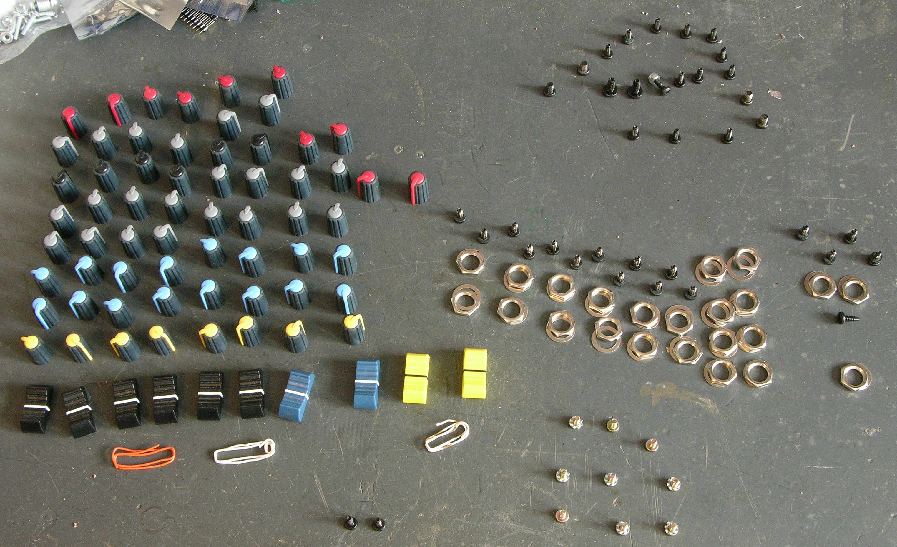
First off, you can’t get into the mixer from the back, so I had to take every knob, screw, and nut off the front panel. I’ve had this assortment on my workbench for several weeks, in the way and patiently waiting for reassembly.
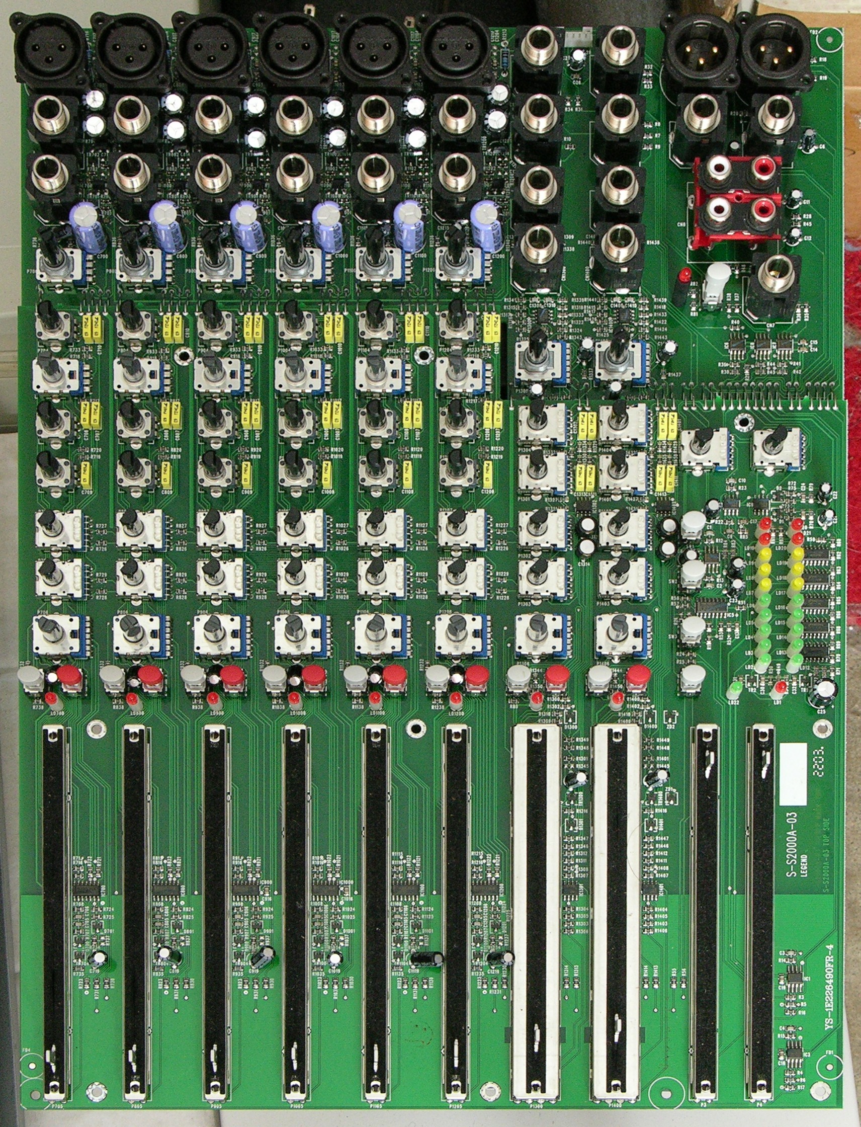
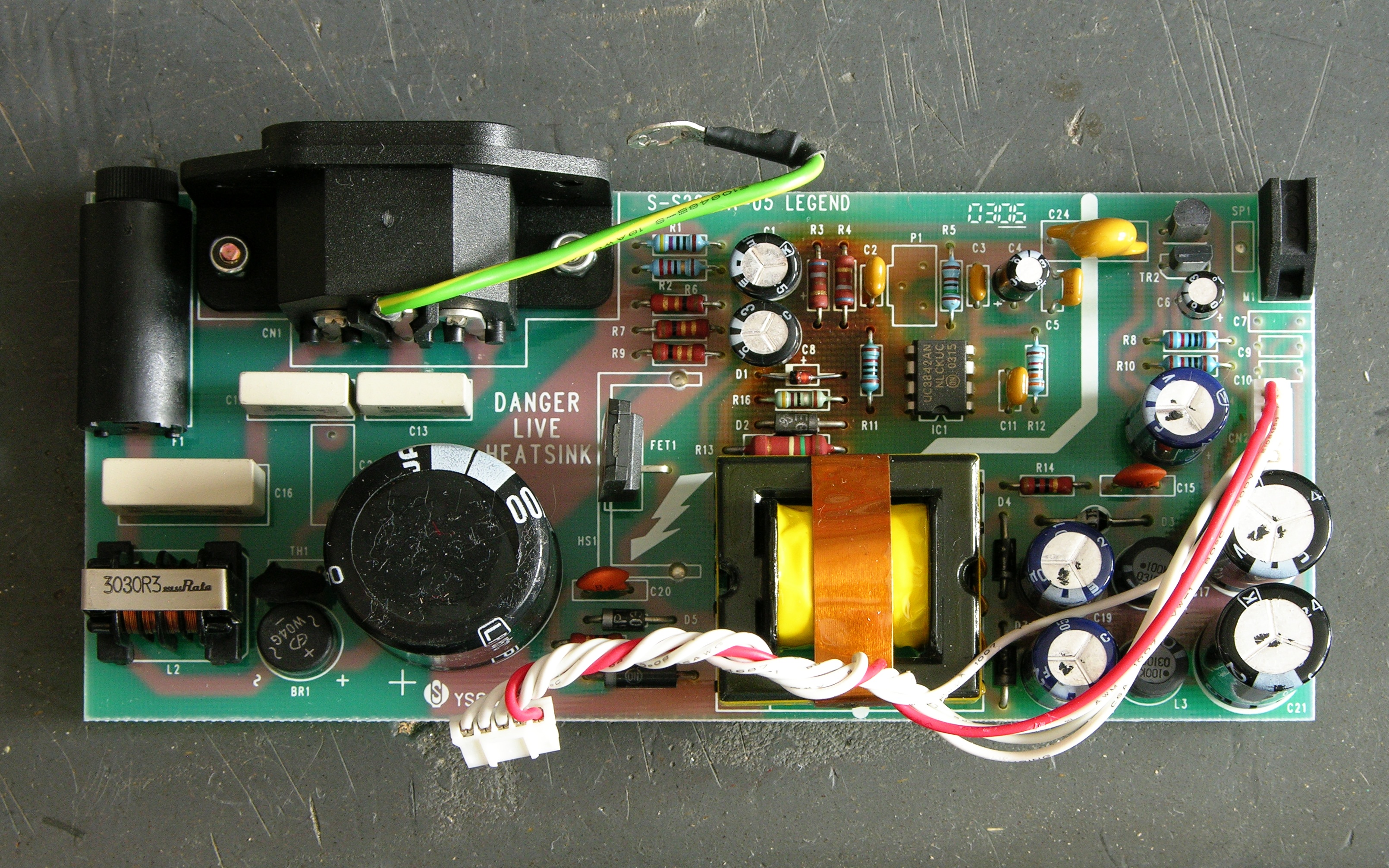
Here’s the main board. It’s so hard to see the active components, it looks almost like it’s just a control board, but that’s the whole deal — all the op-amps are tiny little SMT jobbers hiding between the jacks and faders.
Then I had to dig the power supply out of a gully in the back of the case — yet more screws to keep track of.
Capacitors
See that scorched area in the upper middle of the board? I was suspicious of the two electrolytics right next to it.
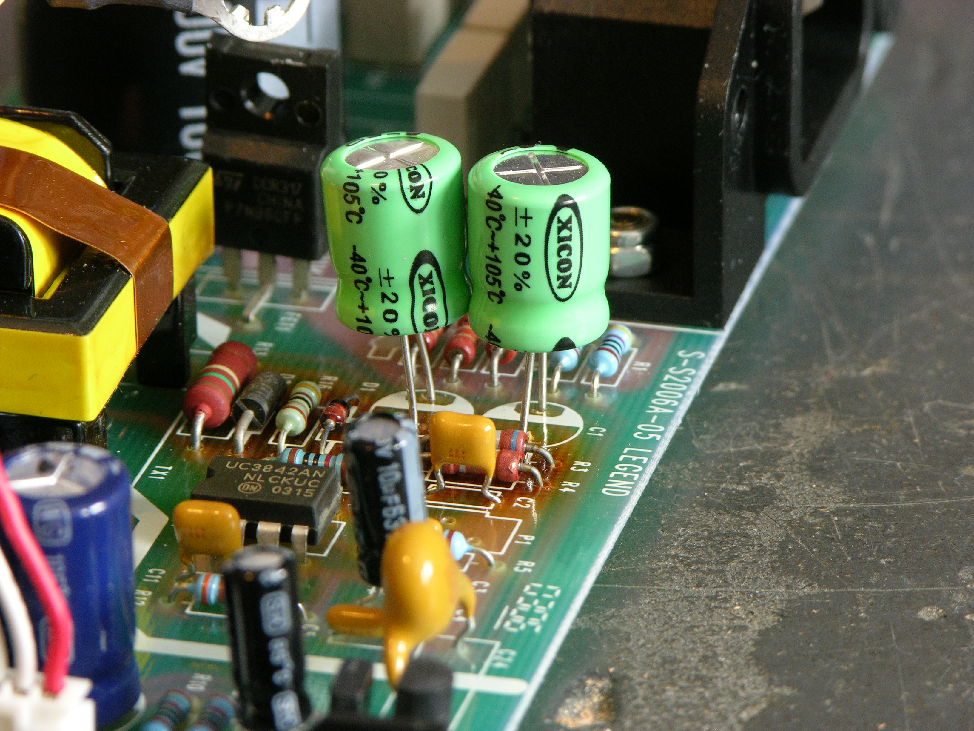
I pulled out Ye Olde Capacitor Wizard, and sure enough, C1 and C8 (47uF 63V 85°C) both tested way bad. I replaced them with 47uF 100V 105°C capacitors, raising to get them a little further away from the resistors that I assumed were the source of the heat. This is probably not kosher, but then neither is failing to take thermal considerations into account and baking the capacitors.
And voom! The power supply … er, still didn’t work. Durn.
Sam’s Switching Power Supply Repair FAQ
Since I knew nothing about switching power supplies other than vague theory — and at the time still had every desire to keep it that way — I Googled for “troubleshooting switching power supplies” and went off to read Sam Goldwasser’s excellent troubleshooting guide. It even has a section on the UC3842 control chip used in this supply.
Alas, none of the problems that “probably account for 95% or more of the common SMPS ailments” seemed to pertain. (I find that they don’t 95% of the time.) Under “Supply dead, fuse not blown,” it suggests a bad startup resistor, bad fusable resistors, and bad controller components.
Startup resistor — okay, now I was having to learn a little more about how off-line switching power supplies work.
In an off-line power supply, ac line voltage is rectified and filtered without using a line frequency isolation transformer. Great; not only is there 110-120VAC in there, and 155-170VDC, but the entire primary side is powered by directly rectified AC and is “live” with respect to earth.
I’ll say it now and I’ll say it again later — don’t poke around in a powered-up off-line power supply unless you have it plugged into an isolation transformer. You don’t want to chance touching a connection that’s hot to earth and having it short through you. You also don’t want to connect the power supply’s floating ground — which is still hot with respect to earth — to your scope’s ground; it’ll send a whole lot of electricity through things before it melts one, the other, or both. For safety’s sake, you’re best off using a battery-powered meter, which doesn’t provide any return path to earth.
Right, back to that startup resistor. In this type of supply, the primary side of the circuit is running off rectified line voltage — in this case, about 170VDC. A high-valued startup or bootstrap resistor is used to provide VCC to the control IC — in this case, as I learned shortly, by charging C1.
The UC3842 control IC is designed so that it turns on when VCC climbs to 16V, increases its current consumption so it’s now draining C1, starts driving the FET to power the transformer primary and hopefully get the supply bootstrapped, and turn off if VCC falls to 10V by depleting C1 before the main supply manages to bootstrap. This is why failed switching power supplies sometimes chirp, chirp, chirp or flash their power LED — which I found out later this one had been doing before it went completely dead.
Once the system is bootstrapped, it draws from a transformer secondary to power the control IC on the primary side.
Startup resistor — right. A bad startup resistor could make the supply never bootstrap. In retrospect, it makes sense that it’s the large resistor in the circuit, because it’ll have about 170V dropped across it, but I wasn’t thinking of that at the time. Which leads me to …
Building a Schematic
Didn’t have one. Needed one. Made one.
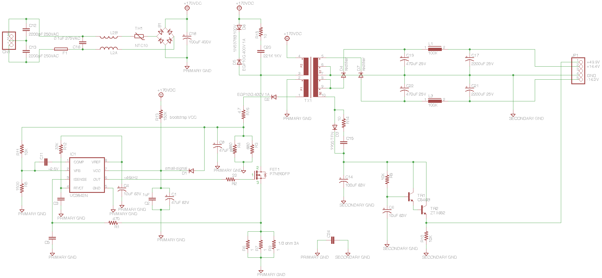
I looked at all the components on the board, placed them in EAGLE in corresponding positions, and then joined connections to follow the traces on the board. Then I rearranged the schematic by logical sections, and that’s what you see here (since annotated with voltages you should see at different points in the circuit, for the sake of the next person to repair one of these).
The whole thing makes a lot more sense now. In the upper left, the incoming AC has RF filter capacitors across it, a fuse, RF filter inductors (it physically looks like a transformer and maybe technically is but the coils are side-by-side instead of concentric and it has an air core), a thermal fuse, a surprisingly small bridge rectifier (high voltage but low current), and a big 100uF 400V capacitor.
The primary side of the circuit charges C1 through R13 to bootstrap VCC up to the 16V turn-on voltage. The UC3842 drives the FET that switches the transformer primary. A primary-side secondary is half-wave rectified to provide ongoing VCC to the IC, and the rest of the primary side is kitted out with all the various feedback the UC3842 needs to operate.
The secondary side has half-wave rectifiers with pi filters (capacitor to ground, inline inductor, capacitor to ground) to provide balanced ± power to the op-amps in the mixer. The oddball dangly thing regulates the 48V phantom microphone power.
I’ll note that brown bands on brown resistors look grey to me, leading to some intial confusion as to resistor values.
Testing Begins in Earnest: Bootstrap Resistor
With the schematic in hand, I could now make a logical progression through the circuit, testing components in turn, to locate the remaining problem(s). My plan was to test the power to the IC, the FET drive signal, then the transformer primary power, to isolate the problem to the appropriate section of the circuit, and narrow down from there.
First I tested the bootstrap resistor, R13. Looked good — and I desoldered and lifted one lead to be sure I wasn’t being misled by some parallel part of the circuit. Seemed okay.
I wanted to check the actual bootstrap VCC voltage, because I was suspicous that it might be too low to turn on the chip. To do this, I needed to power up the circuit, so I did two things: I plugged the power supply into my isolation transformer so if I accidentally touched part of the circuit I didn’t intend to, I’d just be hurt instead of (potentially) dead; and I plugged the mixer’s main board into the power supply on my bench, to provide a load.
Switching power supplies that have feedback from the secondary voltage to the control IC are particular about having a load. Although this supply does all of its regulation within the primary side, changing the load will change the current draw of the transformer secondary which changes the current draw of the primary which changes how the circuit behaves. It might be okay to run this supply without a load; but frankly I just don’t know enough and didn’t want to chance it.
Powered from the isolation transformer, with the main board plugged in for load, and using my battery-powered meter (not essential since the supply was on isolation, but the handheld meter was the first piece of equipment I wanted to use anyway), I measured a fluctuating 12-14VDC on the VCC line.
This told me that the system wasn’t bootstrapping, as it should have a steady supply voltage once running — but of course I already knew that. What it didn’t tell me was whether I had a bootstrap voltage problem. I was using my digital meter, which doesn’t have a fast enough response to be sure about the exact extremes of a fluctuating DC signal.
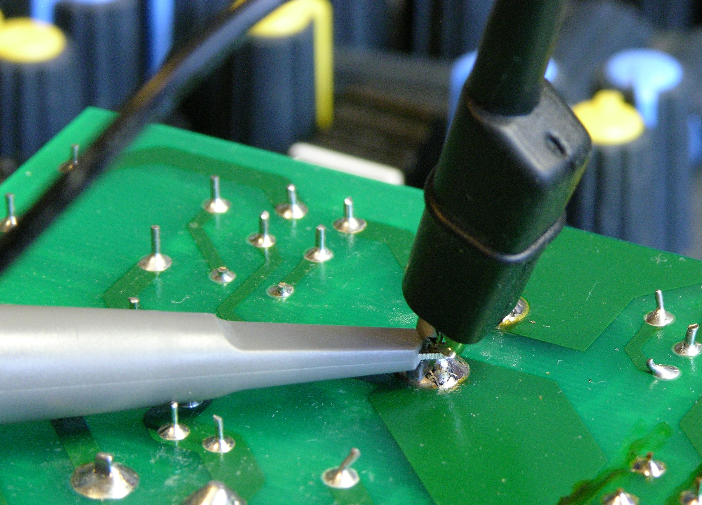
I figured I was going to be spending a fair bit of time testing things on the supply, so I soldered a wire to the primary side’s big capacitor’s negative terminal to use as a ground point to clip my scope’s ground lead to — I didn’t want to try to clip it to a short component lead and have it pop off and touch something else while I was testing.
Scope said 16V falling to 10V on each cycle. Aight, not a bootstrap resistor problem.
Testing the FET
Next I put the scope on the FET’s gate — lack of drive signal there would indicate that the control IC was hosed. I did have drive there:

It shouldn’t be ramping down like that, but that’s just a consequence of the bootstrap VCC draining away C1 as the supply fails to boot.
The next logical point to check was the junction between the FET drain (top) and the transformer primary, but I was still being chicken about hitting that 170V with the scope. Instead, I looked at the cathode of D2, the half-wave rectifier for the primary-side’s transformer secondary that’s the first step in providing ongoing VCC for the control IC.

It’s being filtered by C8, hence the smooth curve — but look at the amplitude. The transformer is providing only ~3VDC to the circuit; that can’t be right.
Now, I didn’t think the transformer was bad, but shorted coils in the primary side’s secondary would result in a lower voltage there and could have this effect. So I measured the ultimate DC output of the secondary side of the circuit — the voltage that was supposed to be going to power the op-amps — and saw it fluctuating from about .5 – .9V. It seems beyond comprehension that all of the transformer’s secondary taps should have shorted coils all at the same time, so I ruled out a transformer problem.
It’s worth noting that I didn’t need to consider a problem on the transformer primary — at least, not any sort of problem I’m familiar with. The two transformer failure modes I’m aware of are an open circuit and shorted coils. An open circuit in the primary side just makes it not conduct and nothing happens at all. Shorted coils decrease the primary inductance and increase the ratio of primary:secondary turns, increasing the secondary voltage (often catastrophically).
Since I had a decreased secondary voltage all around, I assumed there was nothing wrong with the transformer, but rather that there was something wrong with the power going into it.
Back to the FET, then. I still wasn’t ready to poke at the 170V, so I scoped the signal on the FET’s source (bottom), at the junction between it and the current-sense resistors.

Looked basically fine. That is, it was varying between 0V when the FET was not conducting and a higher value when it was conducting. If the FET were broken in a simple way, it would be never conducting (or always shorted), and I wouldn’t see the set of pulses as it pulled up the voltage on the sense resistors.
Fine, fine, FINE. I’ll check the dang high-voltage side.
I did switch the scope probe and the scope to 10x first.

The FET drain looked fine too — 170V most of the time, dropping to about 0V when the FET was conducting.
And I wasn’t dead. Or even injured.
Wait — What Next???
Not a bad bootstrap. Not obviously a bad control IC. Not obviously a bad FET. Not apparently a bad transformer. What the heck???
I spent more time pulling components out of circuit and testing them. C2, the small capacitor that parallels C1 on VCC to catch spikes — tested fine out of circuit. R6, R7, and R9, the current-sense resistors — really 1Ω. D2, the half-wave rectifier for the primary-side low-voltage supply — tested fine out of circuit. R5, part of the voltage divider for the voltage regulation feedback — good. What, what, what.
Bad Zener
Everything on the control side appeared to be operating properly, but the transformer’s secondary voltages were far too low. It really seemed it had to be a problem with the transformer drive circuit, and I wondered whether the FET was weak in a way I was having trouble seeing on the scope — not conducting the full current through, or something.
I found in my parts bin a similar FET also made for ultra-fast switching in power supply applications, albeit at a slightly lower current rating, and swapped it into the circuit. No discernable change. Swapped it back out.

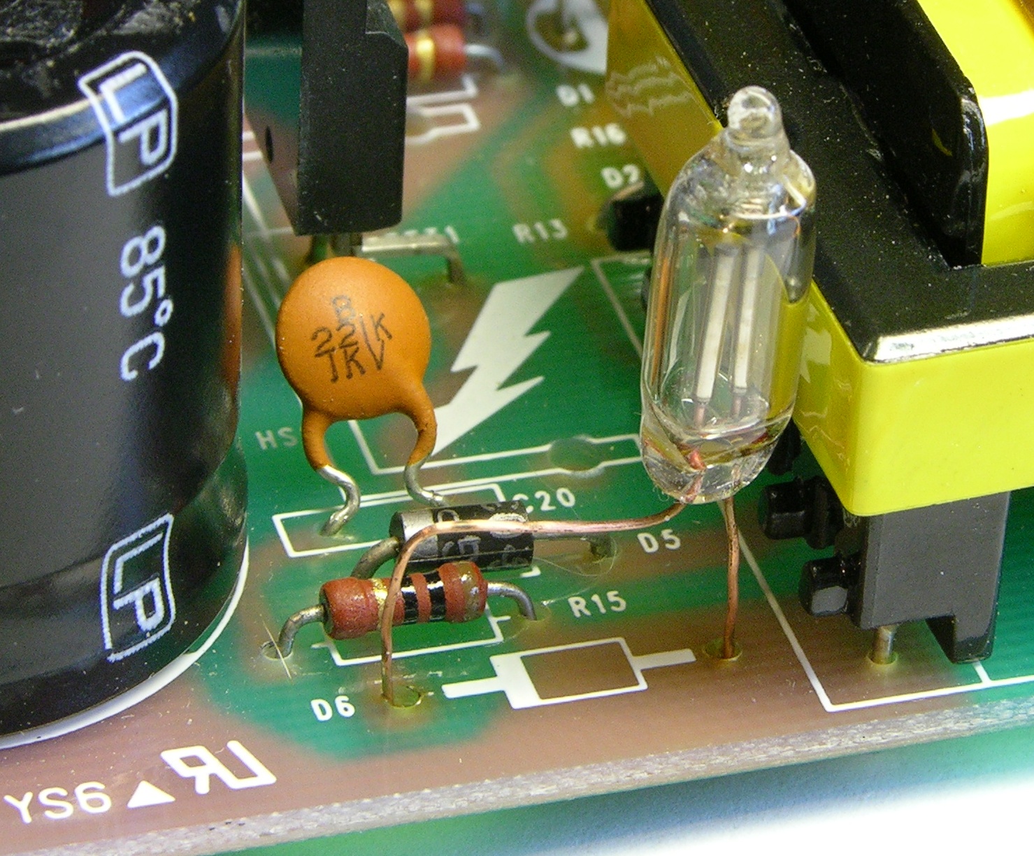
Then I looked up to the network above the FET on the transformer primary — the catch circuit for the inductive kickback. In simple terms, when you’ve been running current through an inductor and you switch off the current source, the inductor wants to keep the current flowing and causes a voltage spike in the opposite direction of your power supply. Placing a reverse-biased diode across the inductor will have no effect during normal operation, but allows the “wrong-way” voltage to be dissipated during the spike, saving wear on the other components.
D5 is that reverse-biased diode, and I hadn’t been able to read a part number on D6 while it was in-circuit (the number was facing down) but knew it must be a Zener — a diode used in reverse, which only conducts (in reverse) when the voltage across it exceeds a certain amount, called the Zener voltage. In simple terms, it clips the (reversed) voltage across it to its rated Zener voltage; or put another way, it doesn’t conduct (in reverse) unless the (reverse) voltage across it is more than the Zener voltage.
So this is a Zener diode, which is used in reverse, applied in the inductive kickback circuit, where diodes are used “backwards,” with the two reverses making it look like it’s used forward — which is why I assumed it must be a Zener. Its purpose must be to shunt the inductive kickback only when it exceeds a certain threshold above the supply voltage, instead of all the time.
I appear to have misinterpreted the function of C20 in this next section. See the comment from MikeS.
C20 is not something I usually see in kickback circuits — the only thing a capacitor can be doing there is catching some of the kickback and adding it to the next forward-going pulse. Oh, very clever! Instead of wasting the kickback by dissipating it all into the power supply, C20 recycles it, increasing efficiency.
And D6 sets the maximum voltage that C20 can catch, discarding the rest. With a traditional reverse-biased diode there, all the kickback would just dissipate through the diode and C20 wouldn’t get to keep any.
I was now wondering whether something was wrong with this catch circuit. It seemed much more likely that one of the diodes would have failed than the capacitor or resistor, so I started with the diodes.
When I measured D6 in circuit, it looked like it was conducting both directions. Oh, I thought, that’s because of other components in the circuit, so I pulled it out and measured it again. Still conducting both directions, a lot. Eureka! There’s the problem — it was dissipating all the kickback through D5, with D6 acting like a dead short, and C20 wasn’t getting to keep any, and C20 was critical to powering the transformer!
Now out of circuit and completely legible, I could see that D6 was a 1N5378B 100V Zener. I couldn’t find anything in my parts bin close to an acceptable substitute, and I didn’t want to place a parts order until I was sure that was the last thing wrong with the supply and I didn’t need to buy anything else, so I really wanted to find a substitute and check. And I had a feeling there was something else I could use, but I couldn’t think of what it was.
Faux 100V Zener
The next day I talked to Tom McGuire and John, asking if they had any 100V Zeners at work and whether they could think of anything else I could use.
They didn’t have any Zeners big enough. Tom seconded my suspicion that I could probably run it without the Zener long enough to test, letting all of the kickback go into C20 instead of shunting some; but I didn’t want to take a chance of breaking something else in the circuit at this point, so I was leery of trying that.
And then Tom reminded me of what I couldn’t think of — a neon bulb.
A small neon lamp will start conducting when its voltage exceeds about 100V (perfect!) and keep conducting until the voltage drops below maybe 60-70V (unimportant for this application). They have a long history of being used as voltage regulators in addition to indicators.
With the shorted Zener out of the circuit and the neon bulb in, the power supply worked and the mixer powered up! I couldn’t ever see the bulb light so it’s possible the kickback was never exceeding 100V, or never for long enough to light up the bulb, but I felt better having it there.
I poked around the rest of the circuit and everything else looked okay. I placed my Digi-Key order for some other stuff that had been accumulating on my shopping list, got the order yesterday, replaced the Zener, and now the mixer is tip-top!
Well, actually no.
10MHz Ringing
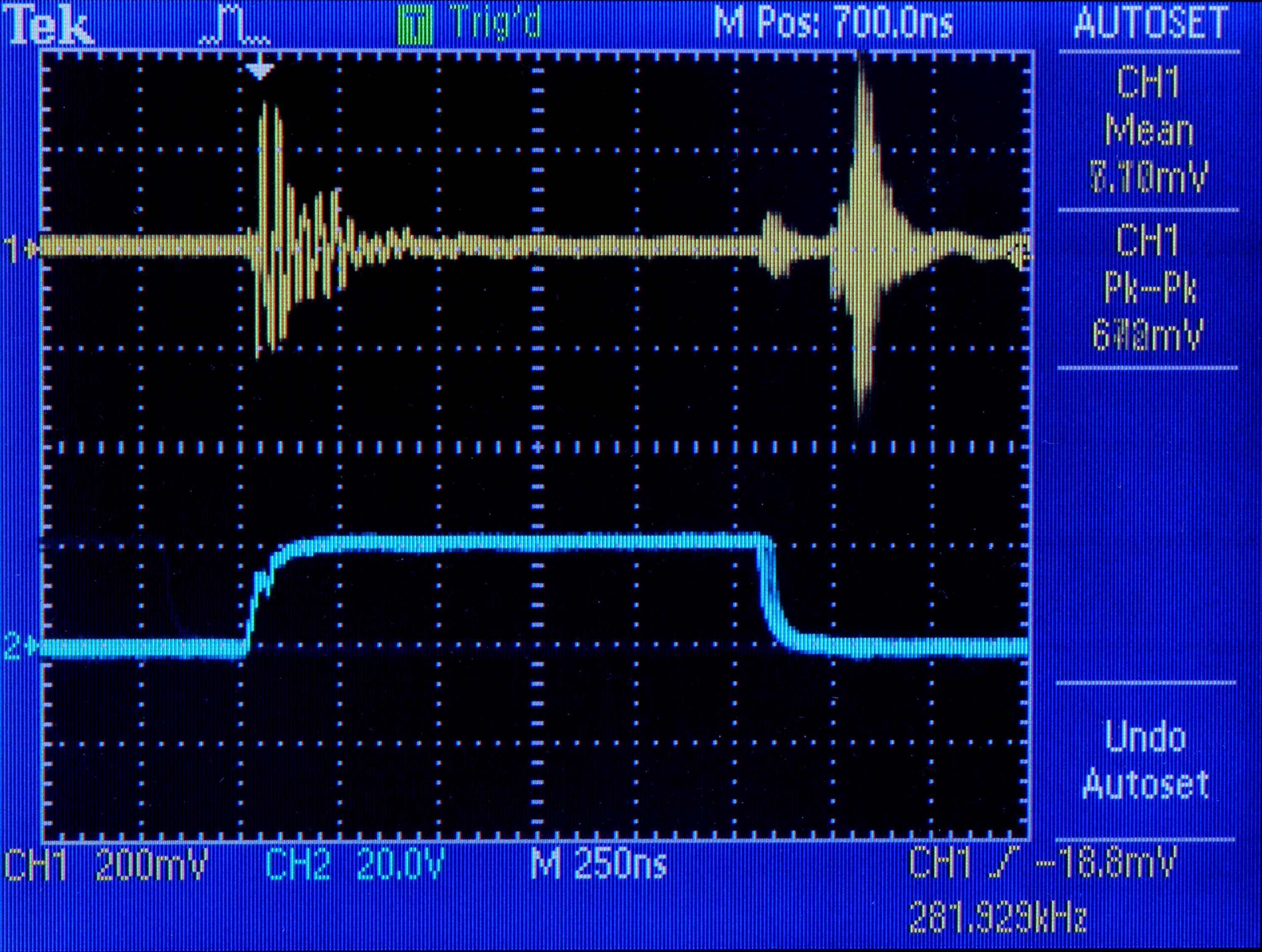
I was going through taking measurements of correct, baseline voltages and frequencies to add to the schematic for posterity, and I noticed that the VCC line looked awfully noisy. I zoomed in on it and found massive ringing, with the leading spikes happening at a period that appeared to correspond with the FET switching frequency and the individual oscillations in each ring at about 10MHz. I rechecked all the capacitors, replaced some anyway, supplemented some, and absolutely couldn’t get the ringing to go away.
Now, 10MHz is way above audible frequency (except perhaps for golden-eared audiophiles ![]() ), so I wasn’t worried about hearing it. Plus it was only on the primary side of the circuit, so I was pretty sure it couldn’t couple through the transformer to the secondary. But I didn’t figure it was great for the control IC to have that on its supply, and I was worried about it shortening the life of other components. So I really wanted to get it figured out before closing up and returning the mixer.
), so I wasn’t worried about hearing it. Plus it was only on the primary side of the circuit, so I was pretty sure it couldn’t couple through the transformer to the secondary. But I didn’t figure it was great for the control IC to have that on its supply, and I was worried about it shortening the life of other components. So I really wanted to get it figured out before closing up and returning the mixer.
I traced the ring to lots of different points in the circuit — back up toward the transformer, all over the place. Finally out of exasperation I put the scope probe on the same ground point I was clamped to, more as a joke on myself than anything — and saw the ringing there too, clear as day.
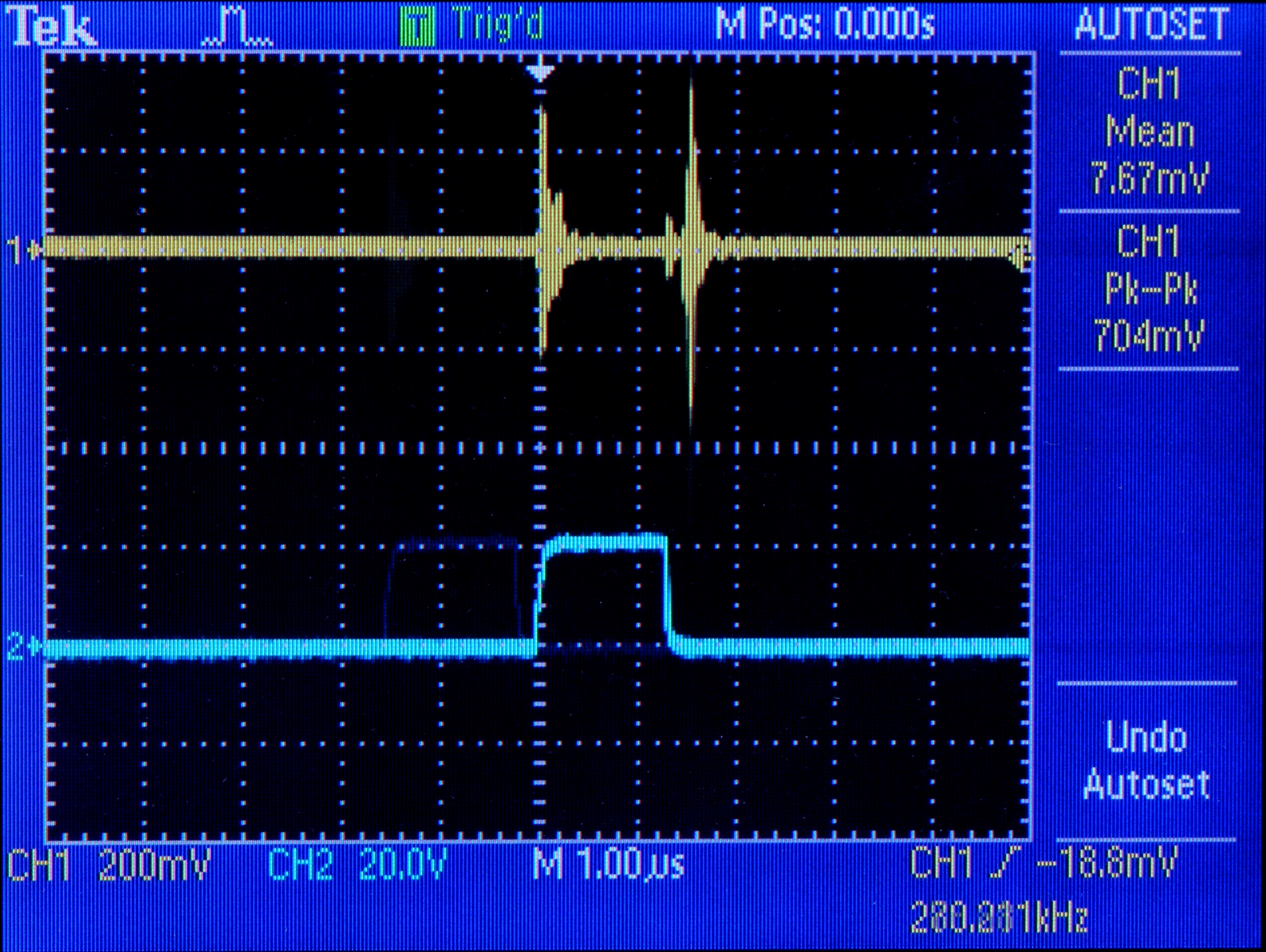
Trace 2 is the FET gate drive; trace 1 is noise on the ground plane. There’s almost a volt of spike on the ground plane every time the FET switches on and off. I hadn’t been seeing noise everywhere else throughout the circuit; I’d been seeing noise as measured between each point and noisy ground.
(Okay, how can a scope register a signal between its probe and its ground when they’re connected to the same point? I assume its ground connection is capacitor-filtered and its probe obviously is not. That could mean that I wasn’t just seeing dirty ground everywhere and there really is noise throughout the circuit — but I know there shouldn’t be that kind of noise on the ground plane, and I want to eliminate that before worrying too hard about the rest.)
Here’s the same thing zoomed in,
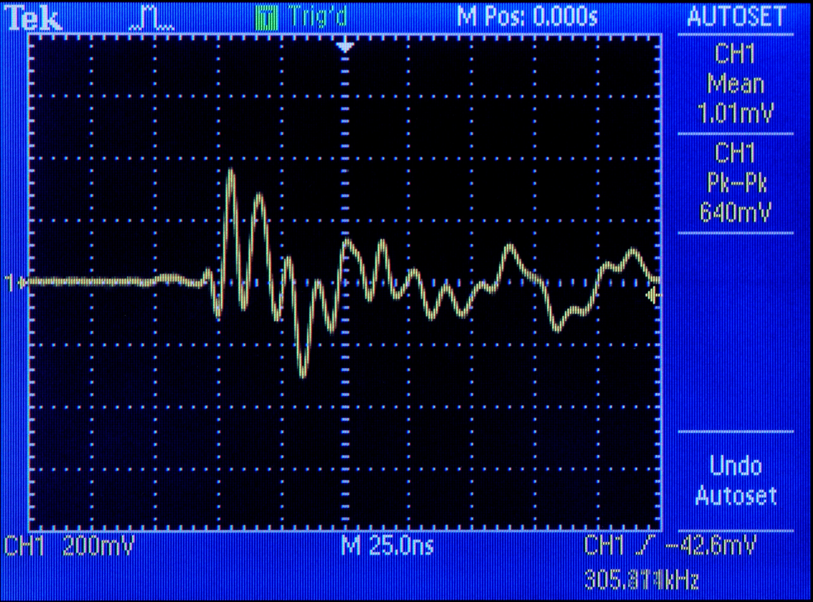
and a closeup of just the first ringing.
To add insult to injury, the only connection between the primary and secondary sides of the circuit besides the transformer is C24, which capacitively couples the two ground planes. (I don’t fully understand why.) And C24 couples the noise into the secondary side’s ground slick as can be, where it appears on the power going to the mixer. Crap.
My immediate intuition was that the big 100uF 400V capacitor across the power supply was aging and no longer able to respond to transients as fast as 10MHz. When the FET switches on, the circuit makes almost a dead short between +170V and ground through the transformer; it seems natural that ringing during the transistions should appear on both the power and ground lines, and C18 is the only thing that would really be in a position to catch it.
It also occurred to me that maybe this ringing has been there from day one, and either the engineers didn’t notice or didn’t care. But that’s not a happy thought; and as I don’t have access to an identical mixer to see how it operates, I’ll just push that back to the dark, cynical recesses of my mind.
C18 has a lot of capacitance; but it’s so big, it might not be able to respond quickly enough to very fast spikes. This, I assume, is why C2 is paralled with C1 — so perhaps a smaller-valued capacitor in parallel with C18 would help kill the 10MHz ringing. (Perhaps a brand new replacement for C18 would do the job also — but if that fixed it, then in a few years the new capacitor would have aged enough to regain the same problem. Better to fix by design than by manufacturing.)
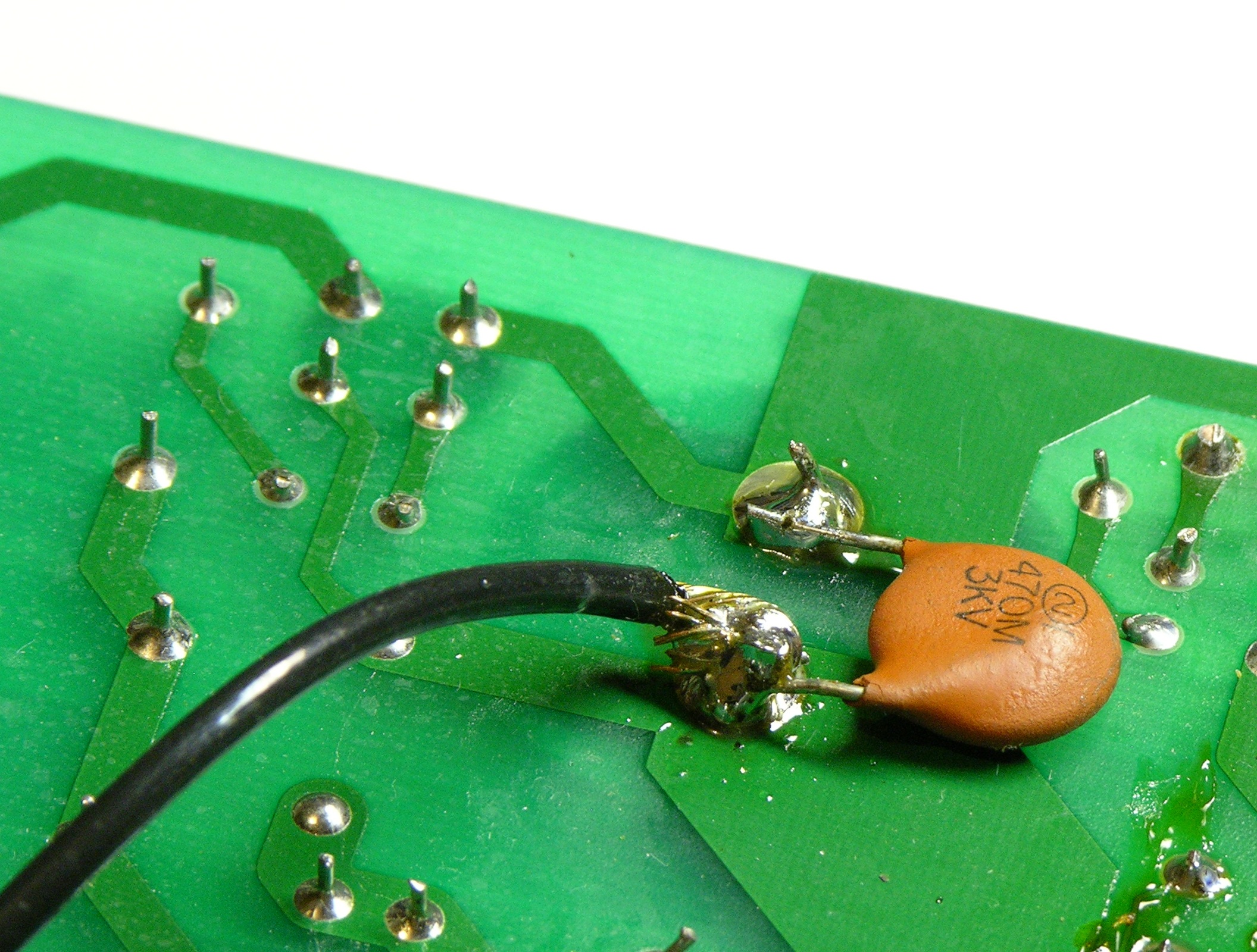
I found a 330nF capacitor that looked like I could trust it with 170V plus spikes and soldered it on in parallel with C18, and it doesn’t appear to have made any difference. Also tried 4.7nF, 150pF, and 47pF (shown here), all with no apparent change to the ringing.
I don’t have many ideas left, and I’m really not happy leaving the power supply the way it is. Maybe someone out there with more design or repair experience has a suggestion? Maybe the scope is playing tricks on me and someone can explain how?
Hello there,
i have read all your posts, i have an E6 with a bad power supply, could any of you fix i for me?
Best regards
Hi Keith.
Do you have andys email logged? If so could you possibly email him ? I guess you wouldnt want to give me his.
Im very new at all this electronics stuff so dont know. My colleague whos looked at it reckons its fried… the board is very black and charred!
Im looking forward to the challenge and learning experience of building a new one.
Many thanks.
Ben
Ben, if we don’t hear from Andy in a few days, ping me again and I’ll email him to ask if he’s willing to get in touch with you.
Don’t toss the charred board. I love a challenge!
Hi
many thanks. Im in no rush this things been dead for ages.
Im going to get a linear supply together soon.
If youre interested, I can post it over to you. I was only going to throw it out.
Cheers
Ben
Hello Ben,
I am surprised at the number of PSU failures there are with range of mixers. Undoubtedly the Achilles heel. Basically the situation is this. With the Spirit ES, only the mic inputs need +48v from a PSU. The stereo inpuut channels including the phono do not require the +48v rail.
For all Spirit E models the +48v rail is needed for all mic channels, even if you jack into the line inputs of these channels.
However, if you have a Spirit E, the mic channels can still be used as line level inputs if you connect your input to the ‘INSERT’ jack. Here you need to feed the signal in using a TRS or Stereo jack plug with the signal connected to the ‘ring’ or middle connection. The fader and tone controls will function but there will be no GAIN control (red knob). All other INs and OUTs work just fine with just +&- 15vdc rails.
I am now using my Spirit ES with an external linear PSU and we are friends again . I do hope this is of some help
Andy.
Many thanks for the reply. Bit of a strange situation that, but it doesnt seem much harder to build the 48V rail as well as the other two while im doing it anyway.
Many thanks for the reply, information and schematics. Very helpful.
I have acquired a set of schematics for these mixers if they are any use to anyone. Leave a reply with email and ill send them on.
Keith – got your email thanks, I have replied privately.
Many thanks
Ben
Jes, I could probably fix your power supply. Are you in the US (low-cost shipping), or in what area are you hoping to find someone to do repairs?
Hi, Soundcrafters!
I, too have a PS board for a Soundcraft Spirit ES that needs repair. Anyone up to the task?
Thanks,
Randy
Santa Rosa, CA, USA
Sure, i`m from Denmark, so shipping should be no problem
Randy, I’m willing to give it a shot.
I hoped that some of you guys could fix my ps for the soundcraft
Keith
good try at fixing the SMPS. youve done well. Heres my 2 cents worth. This is a flyback SMPS by the looks of it, d5 and D6 are snubber components, which are there to quelch leakage inductance energy back to the DC bus (170V) when the switch turns off ie when the switch turns off, the drain of the mosfet actually goes above the bus voltage
so Vd = 170 + reflected voltage + leakage voltage. This may exceed the rating of the Fet and D5/D6 provide a path for this high voltage to be dumped back into the capacitor. If D6 is ocnducting both ways (IT SHOULDNT), replace it with a same value zener (or 2 or 3 that add upto 100V at least 1W package).
As for R15 and C20, these i believe are only there for EMI, as C20 is far too small for anything else. my guess is that the smps is radiating noise at some megahertz due to L and C parasitics in the transformer.
anyways, great website mate…keep it up
Hi folks, just come across this site. Yes I’ve got a charred power board, that I must say I haven’t a clue how to fix. Is there anyone that could help me get this puppies singing again, would be Very grateful. Thanks
Paul, if you’re interested in shipping it to Kansas, USA from wherever you are, I reckon I could fix it.
dear Ben,
i have Soundcraft MFXi20 burned at switching PSU, do you have any electronic circuit diagram (schematic) for PSU.
Any help please
Could you say, what is the transformer ? (type, kind, part nr, any inform.) mine is burned ((
((
Hello everybody,
I have a blown e12. After I replaced the Power-Supply (soundcraft replacement board) the mixer woke up again. BUT: The Master Section didn’t work.
replaced IC1/IC3; C3/C4; R14/R15. The Signal I get before these components is fine. After these Components, before the Insert TRS, I have a no signal but a (i think its 100hz) sine but no signal. After the Insert TRS everything works fine (I checked – I fed the TRS with a separate signal), so IC1/IC3 work. I also checked the replaced Cs and Rs and they do their job.
When I power down the mixer I (shortly) get the input signal out of my master section. –> I checked Power Voltage at the ICs: Fine – doesent differ from the other ICs which all work. AUX-Busses work, Solo also works.
Does anybody have an idea what I could do or where the issue could be?
Thanks for your help.
Hi Keith !
Thank you for this great post. I found exactly the same failure on the power supply of a Soundcraft mixer. I have to replace the Zener diode.
I also need to find a missing capacitor (C16). I can see that it is a 0.1µF 275VAC thanks to your schematic, but could you provide me with all the specs of this capacitor, like its type Y2 or X2 ? (I am quite a novice…)
Regards,
Marlin, I don’t have access to a Soundcraft, so I don’t have any way to check. Perhaps someone else can look for you?
Marlin – I am working on a supply from an EPM 12 (with at least a bad zener and bad D3); my C16 is a Panasonic ECQUL series X2.
Keith – Excellent article; I am so glad I went several pages in on my Google search. The 10Mhz signal on the scope when probing the ground point is possibly because the probe ground lead is not shielded, and provides a handy antenna for the (probably parasitic) RF output.
I never never thought I would find an article dealing with this power supply …found the same diode shorted and another fast acting diode in the secondary circuit bad. (may have caused that by powering up supply with no load.) So now You have given me hope of repairing this rather poorly built unit (found the foil comes off the board too easily). Thank You so much for writing up your repair history…just simply excellent. (will find a neon bulb…)
Dave (math teacher, Prep School in Ontario)
this is going to sound dumb but I came across one of these in a storage closet in our studio and can’t figure out how to turn it on? I plugged it in and can’t find the power switch/button… any help?
Jim, I’m sorry, but it’s been three and a half years since I had access to this mixer and my memory is not that good.
There is no power switch on these. Plug it in, and check the “POWER” LED just above the two “MASTER” faders. If not lit, start at the beginning of this blog.
I like these and use several at small FM stations in my area.
Brilliant info!
Your circuit is very similar to the M12, which has a different board, so component IDs differ, but most values match.
My 100V zener also reads the same in both directions (0ohms) so just ordered one from Amazon for £5.70 inc P&P.
Many thanks.
Hi have similar problem with my M12 mixer unfortunately I can find the 1N5378B here in Dubai as well in the Philippines any idea where can I get this part?
thanks and nice info from you
Many thanks
Hi!
Im really glad to find this blog. I’ve got one of these Soundcraft mixers laying around for over two years now. Not working ofcourse.
I just have the slightest electrical knowledge and a buddy of mine didn’t want to touch the PSU. He probably already saw the amount of work commin you put in it.
With this blogpost I might be able to fix it with a little help from friends. Might try it sometime in the next couple weeks. I’ll let you know if it works or not.
Your blog’s still usefull after all these years
Greetings from Holland
Somebody has a diagram for this Soundcraft Spirit E12 mixer?
Can’t find it anywhere -urgent need for repair. Thanks for help.
Victor, I found quite a few sources for the zener diode on the internet (including Amazon, eBay & Farnell) but don’t know what options are available to you.
When fitted, I calculate the mixer worked for about 1000ms before the replacement failed!
According to SoundCraft, if you are going to try replacing this, you should replace all silicon in this circuit at the same time. A new board from SoundCraft was quoted at just under £100, so we dumped the mixer.
Once again , I have the S/craft pdf for these mixers. Cost me a tenner 8</
Anyone who wants a copy e mail me
Farquhar at ( inbox dot com )
As a solution I got hold of 4 0-15v psu packs , the little rectangular ones. Inver one for -15v and cascade the rest to give +15v and +45v . Works a charm. The PSU's are external to my EPM12
Thanks for this blog, I easily troubleshoot the PSU. Just replacing the D3 and D6, the PSU works again.
Thanks A LOT for your work – I’ve purchased a damaged Spirit ES (for ~50$), assuming it should be relatively easy to repair it – the power supply is badly broken (more on that later), and there are some 3 opamp chips desoldered on the main board. Yeah, I’ve no idea why – pretty expensive source for TL072s
I’ve found a service manual PDF somewhere, but it’s very badly scanned – it’s enough to get the idea of the circuit, but it’s next to impossible to read part designators/values – so I have to use it looking at the board at the same time, figuring out which part is where on the schematic, etc. Perhaps you have a a better one?
So, I was really happy to find the PSU schematic on your page, that’s very helpful. And fortunately, the PSU is simple – I was (successfully) repairing E-Mu XL7 PSU some time ago, that was a nightmare – 2 UC3842 chips, 2 trafos, feedback via optocouplers – pretty complex stuff was going on there. But well – 5 output voltages!
Speaking of the Spirit PSU – some idiot was trying to repair it already, having no clue about it – he was trying to replace each and every part, one by one. To make things worse, he had no clue about soldering – I have all sort of damaged pads and tracks now to deal with :-/
Anyway – thanks again for the great post!
I have one of the E6 units and the P/S is not working. I have followed Keith’s excellent report and have changed the two diodes and the capacitors in the areas Keith detailed and have checked as best as possible a number of other components.
My first test was with the new Zener and nothing happened — I did not take any voltage measurements at that time — and I assumed that the D5 diode was faulty. I had to buy one of these.
After replacing the D5 diode, as soon as the unit is powered up D6 (Zener) immediately gets very hot and starts to emit smoke and at the 170V point near D6 (at least) there is zero voltage.
The diode I had to use for D5 is BYV26E — 1000v, 1A, 75ns —as the EGP10G diode was not stocked.
I have not yet tried a new FET and the transformer appears to be OK (resistance wise it gives about what I would expect).
The P/S was connected to the main board before powering.
Anyone else experienced this problem, especially when before I replaced D5 the unit could be powered up without any component heating.
Any advice would be greatly appreciated.
David
Send me your e mail address and I will forward the service .pdf FOC !!
Hi Farquhar, I would sure appreciate it if you’d send me that PDF, as well. Of the four ESs I’m running, only one has failed (so far). Sure would like to see the service notes.
Thank you!
Randy
Randy I need your e mail address , send it to farquhar@inbox.com
This blog will not carry that kind of file AFAIK.
For what ots worth I just went outboard with 4 x 15v packs at 10 buck a shot. Invert one for your -15v and then cascade the other 3 like a transformer multi tap , give you +15 and + 45.
Scrap the internal job , the access points are on the mother bd
You will prob find a few ic’s toasted as well
Hi Everyone.
I know this is an ancient thread, and at the risk of sounding like all the above, this has happened to me too!. Sigh.
That said, I’ve traced my issue to an open circuit in the N side of the 3030R3 muRata EMI Filter (L2B in your circuit diagram (which is very helpful – thanks!)). As far as I can see from muRata’s site, it’s a Sectional-wound EMI filter, but they don’t list that part anymore. Anyone have any ideas for a suitable substitute? The PLA10AS3030R4R2 seems closest to me at this point. Any advances/opinions on that, given it’s not a sectional wound (and thus not as high frequency)?
Also Farquhar – that service PDF would be fantastic if I may – email sent to you.
And for those stumbling over this who are really not sure (and soldering may be a challenge), http://www.fullcompass.com/product/239747.html seems to be an easier alternative to throwing out your Mixer. – I’d rather replace the $1 component on the PSU if I can though..
Thanks in advance everyone, and apologies for continuing this page’s resurrection if you wanted it to just quietly fall away..
Regards.
Chris.
The PDF I received from Lindsay is a picture of a Soundcraft board in a road case. Still have no schematic for a Spirit ES.
I have cobbled-together the 4 X 15-volt supplies, and the board is back alive! Until I started to plug-in a set of headphones (fortunately not wearing them). Very loud click. Seems like there’s -15 V on both right and left ears. Both ICs are shorted. Cannot read the faint numbers on the tiny ICs. Anybody know what they are and where to find them? And maybe a midget with X-ray eyes and a teensy-weensy soldering pencil?
Thanks for any and all,
Randy
Randy, I’m pretty sure it’s NE5532. I had to replace them, too (and a few other chips, as well as the whole PSU board). My Spirit must have suffered from some overvoltage spike.
Speaking of schematics – google for “e8 mixer schematics” (it’s pretty much the same around the phones output). Also, there is a full service manual available for the whole E-series (but it’s a poor scan), you should be able to google it (if not, I have a copy).
what is the values of R1,R2,R6 resistance ..?
Valor de los componentes que se queman frecuentemente en esa fuente
S-S2006A-05 LEGEND:
IC1: UCC3842A
FET1: STP13NK60Z/FP
R6;R7;R9: 1 ohmio 1w
R1: 470 ohmios 1w
R2: 22 ohmios 1w
C8;C1: 47 mf 35v
D3: MUR4100
D6:P6KE200
D5:EGP10G
NOTA : La fuente que repare tenia un arreglo de fabrica en el pin 5 y pin 6 tiene una resistencia de 22k ohmios 1W de pin a pin .
Hello ben I have the same problem here the power supply i am fixing is chirping and I wlso dont know how to remove it. I change the diodes capacitors and the transisyor it has. Also no progress .
Hi guys this is a fantastic “how to” I trained as an engineer at a Music shop in Manchester England early 80′s and was a wear of “soundcraft” good quality products on the whole – PSU though a bit rubbish it seems…
Any way a chum of mine had a “E8″ stop working and guess what it was…
Back in 2002(when it went faulty I said I’d look rather than bin it).I tried to find any information and couldn’t really so I contacted “Soundcraft” via email:
Dear Ian,
the schematics for the PSU come as part of the technical manual for the E series range consoles which is £130.00 . Price for the replacement PSU is £47.80 plus carriage & VAT.
Please contact us if you have any questions or if you wish to place an order.
Regards
So quick as a flash I left it…But today I have checked D3 the “Zener” and after lifting on side off the board, its “short circuit”,the caps don’t “look” bulging so I’m going to lift and check with an analogue meter…Thanks again for a top Thread…
D3 on the CCt is:
SF1600v –
VISHAY SF1600-TR Fast / Ultrafast Power Diode, 1.6 kV, 1 A, Single, 3.4 V, 75 ns, 30 A
hi everybody,
someone can give me the value of the D3 diode ( mine is burned…), C15 value?
and if someone have the reference number or somewere i can buy the yellow transformator with 4 in primary and 6 in secondary…
thousand thanks !!
Loic/ sls-lehavre@hotmail.fr
For those looking for the schematic diagram: http://codepainters.com/soundcraft_psu.pdf
I have re-drawn it myself, both schematic and PCB. I was repairing a badly broken one, had to manufacture a new PCB.
Just wanted to drop a thank you for leaving this on the web. Running through your diagnostic procedure helped me fix a broken Soundcraft M12. Not exactly the same PS since one side of the board is USB. But it’s amazing how close the PS side is. Also, the detailed helped a lot since I am not experienced enough to do a trace of the voltages. That provides quite an education! I have a second board with a dead PS that I’ll be looking at and hopefully fixing this week. Full Compass lists my supply on it’s website for $129 and 7-14 days to ship. I waited for 3 months before I finally cancelled that order.
Fixed one of these today.
Fairly routine stuff. Diode short cct, available from RS. Replace the electrolytics to ensure a bit of future reliability.
Only thing I would add is, if the pcb is carbonized, be sure to scrape out the carbon and make the pcb good before replacing the damaged components. Also replace R15 with a 10r 2w and form the leads so the resistor is off the pcb. It clearly runs hot and is probably the root cause of problems with these power supplies.
I have a badly burned up resistor on the power supply board of my spirit M4. Ii is impossible to have a reading in order to replace it. It is R45. Would anyone have a same mixer and could tell me the value or a schematic of the board?
Very interesting blog… I was shocked to see a request from Soundcraft for £130 for a service manual… here is access to a free one…
https://elektrotanya.com/soundcraft_efx12_efx8_mixer.pdf/download.html
I have owned several Soundcraft mixers over the years and currently have a couple of Compact 4′s that run 12v external PSU… after reading the horror stories here of the bad design of these Soundcraft PSU’s… I won’t be buying any more Souncraft Chinese made products! Looks like Soundcraft had their hey day and are now just trading on past glory and good name; shame