Parts Arriving
While I was away directing camp, several things came in the mail. I now have my A6276 LED driver samples, my DS1302 real-time clock samples, and my 32kHz crystal oscillator samples. The DS1340 RTC samples are awaiting factory approval (whatever that means). My LEDs left Hong Kong on Saturday, and don’t yet show up in the USPS tracking system.
I’ve been studying the datasheets to start figuring out exactly how to interface with the different chips. That includes learning about the I2C (Inter-Integrated Circuit) bus used by the timekeeper chip with the integrated crystal. There’s a nice technical overview of I2C over at the Embedded Systems Academy that’s helping a lot–it looks like I2C should actually be really easy to do in the LogoChip.
LED Drivers
I wanted to start testing with the 6276 LED drivers, since I know I’m going to use them no matter what. (I’m not sure I want to start interfacing to the 1302 and 1340 until I have both sets of samples.) The 6276es are also pretty simple to work with, as shown by my horrible test circuit.
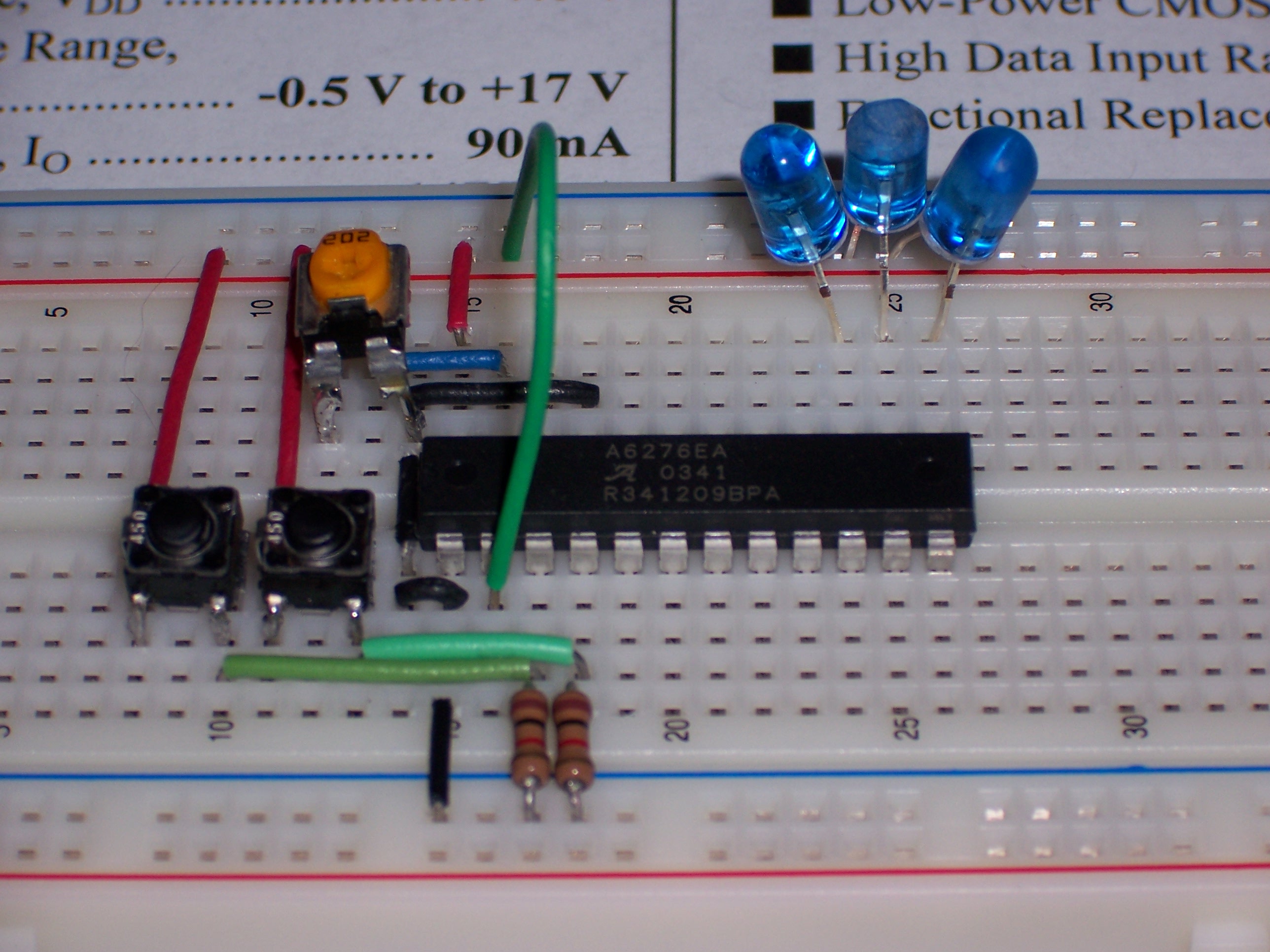
The green wire is the data input, which I’m plugging directly to ground or +5V to set a level. The two buttons (salvaged from a dead CD-ROM drive–seriously, I don’t buy anything I don’t have to) are the clock input, which shifts the data into the input register; and the latch input, which latches the current input register into the output register. Yes, the switches “bounce” and generate multiple electrical pulses–it only takes a few presses of the clock button to fill the input register with 1s. C’est la vie. Since that’s what I was trying to accomplish anyway–demonstrate that this chip can turn LEDs on and off–it works out.
Mmm, housekeeping. The clock and latch inputs don’t have internal pull-up or pull-down resistors, so I added external pull-downs. (The inputs are active high, so I tied them to ground to use with my normally open pushbuttons.) The black wire in the upper section is the active-low output enable, tied to ground to activate the output all the time. And the orange potentiometer is the reference resistor to set the LED current. The 5V leads from my bench power supply connect off to the left of the picture.
It makes the LEDs light! It’s as simple to use as the datasheet makes it it look! And the LEDs are bright, as Jeremy and I had already discovered. I accidentally looked at them from up close, and literally couldn’t see what I was doing while swapping them out for some that I’d manipulated for broader viewing angle.
The only drawback is that my 5mm LEDs don’t fit side by side in the .1″ breadboard. If I cared enough, I could bend the leads so they fit in a /\/\/ zigzag pattern, or prototype a PCB just for playing with the 6276. But I think I’ll wait to cut a board until I’m ready to make the first digit.
Cool. Next: software control via the LogoChip.