I’ve been dissatisfied with having the CupCake’s extruder controller attached to the front of the extruder. The PC board (being opaque) blocked the view of the feed mechanism. As much trouble as I have with filament feed, it’s pretty important for me to be able to keep an eye on it.
Actually, as many times as I’ve had to disassemble the feeder (replace broken idler pulley, reglue idler pulley, remove broken feed pulley flange, replace broken plastic?, etc.), I also got tired of having to remove the PCB every time.
And <whine>the patch cord didn’t route nicely from the side of the machine facing forward to the top of the machine facing up.</whine>
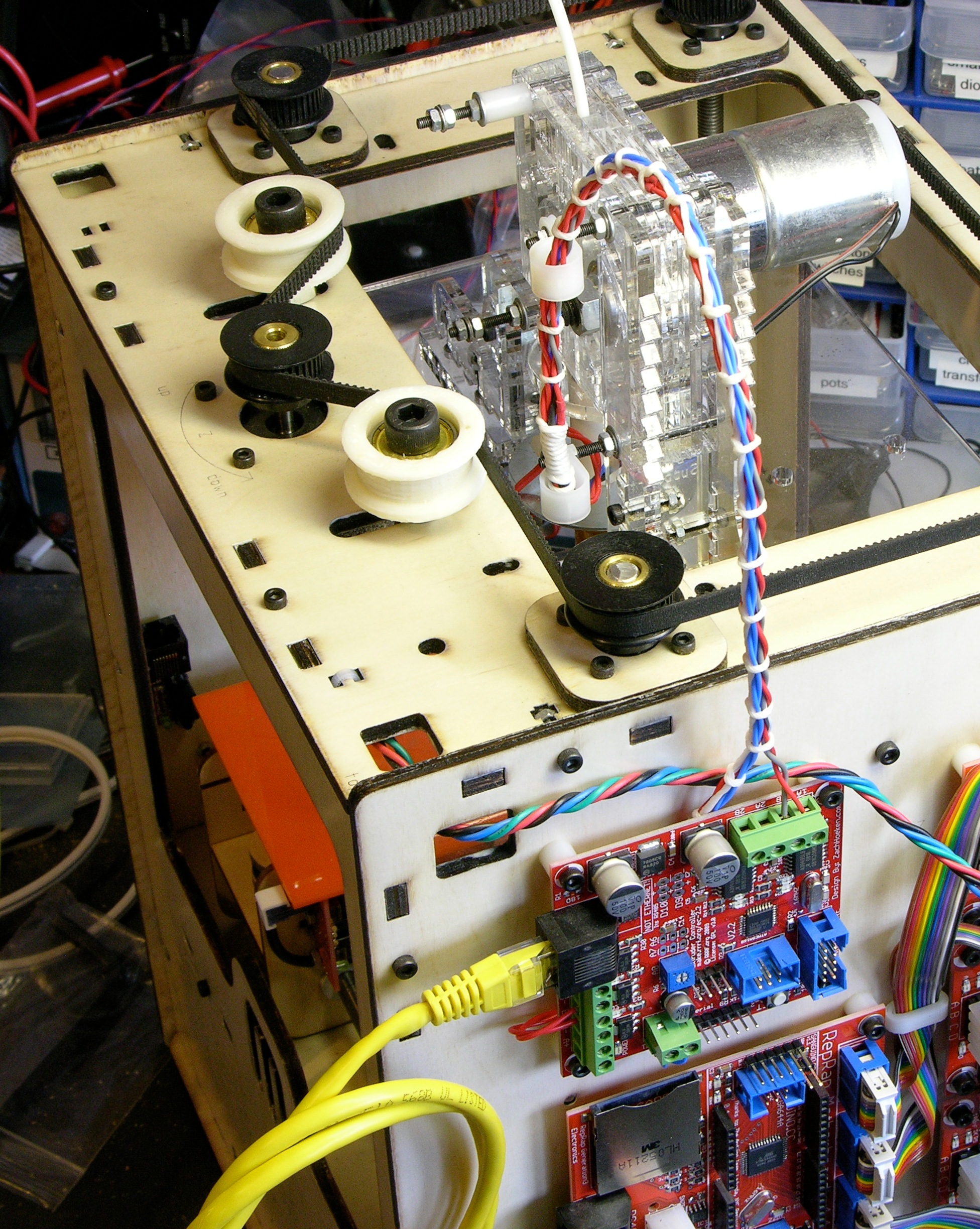
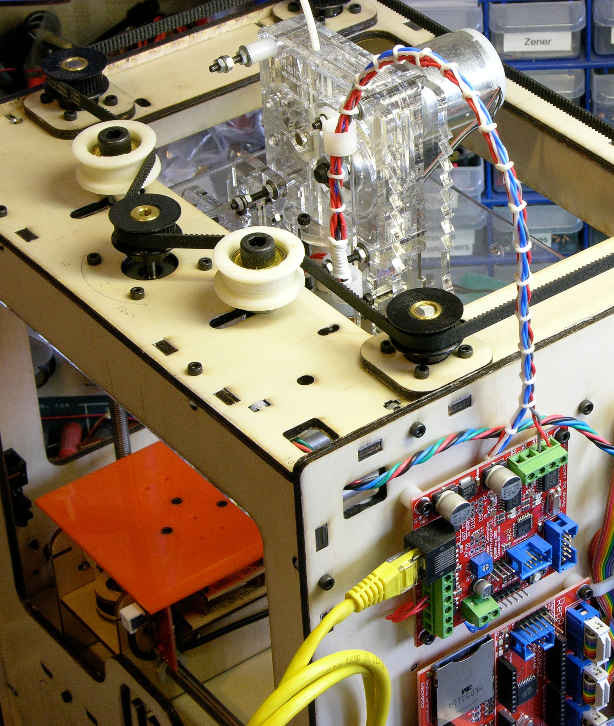
I’d previously mounted the extruder PCB up on the highest two screws of the extruder housing, placing it above the feeder face instead of covering it, but that was pretty fragile and I was constantly worrying about bumping it and snapping it off. This weekend I moved the extruder controller to its new permanent home on the right side of the CupCake in the empty space above the motherboard. It fits nicely and shares a mounting screw with the upper Z-axis endstop.
It does block access to the SD card slot, but I don’t use SD cards anyway. Even if I do someday, I think I’m most likely to put a card in it once and leave it there for doing prints without a host computer connected. Now that I’ve eliminated printing stalls and blobs, I don’t have a lot of reason to try uploading designs to a card every time before printing, nor save designs to a card from the host to then install into the machine.
When I have time, I’ll make a shorter (4″?) patch cord to jumper from the motherboard to the extruder controller without all the excess I currently have coiled up.
Cable Lacing
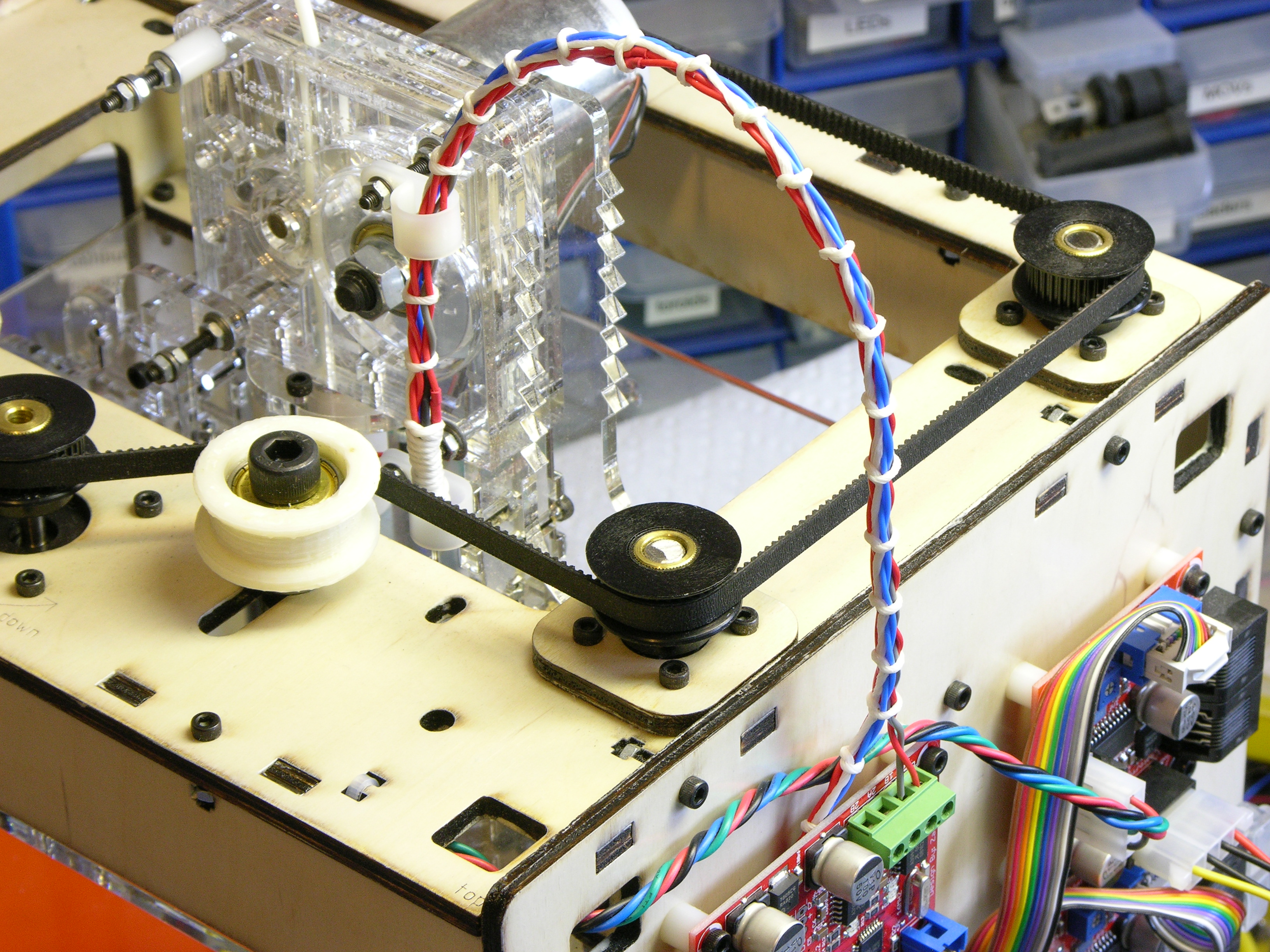
I also got to try my hand at cable lacing, something I’ve long admired in old TVs and vacuum tube organs. I don’t know that it’s the right look for a modern rapid prototyping machine, but the waxed string cost only a pittance and it doesn’t have to be the permanent solution.
The cable clips I had on hand were too big to anchor the mobile end to the extruder properly, but they do help guide the cable until I can buy smaller clips. Initially I had thought I’d need to enclose a piano wire in the cable bundle to help it maintain its arch, but it’s flexing very nicely without additional support.
Extruder Wire Gauge and Current
I’ve been concerned about the ability to deliver enough power to the extruder controller over the ethernet patch cord, especially when people are running heated build platforms off it too. I realized after the fact that I should have checked the wire gauge I was using before extending the heater wires out the top of the machine, but let’s check it now.
Powerstream.com provides a wire gauge and current table and calculator. For the 24-gauge wire I used, they list the maximum amps for chassis wiring as 3.5A, which is a comfortable margin over my actual current of 12V / 6Ω = 2A, so I’m safe.
Toward the bottom of the page they have a load calculator. Entering 24-gauge copper, 12VDC, 1.5′ one-way length, and 2A, they show a round trip .158V (1.32%) drop in the wire and 11.842V delivered to the nichrome heater. Not too bad.
While we’re here anyway, let’s do the math for running both the nozzle and platform heaters from the extrusion controller in its original configuration. The interface uses three wires of the (almost certainly) 24-gauge patch cord for each of 12V and GND, so that’s equivalent to just over a single 20-gauge wire.
The nozzle heater was 2A and I see people talking about 4-6Ω platform resistance for another approximately 3A. The chart says 20 gauge is good for 11A for chassis wiring, which is a comfortable margin. The calculator shows a .314V drop over the 3′ patch cord, still delivering 11.7V to the extruder controller. Quite acceptable and nowhere near as bad as I feared.
If you rotate the motherboard 90 degrees counter clockwise, you’ll get the best of both worlds – relocated extruder board and access to the SD slot. I also rotated the extruder board 90 degrees for easier wiring. I like how you ran the extruder wires under the board. Does this cause any RFI?
http://makerblock.com/2010/02/alternate-alternate-extruder-controller-mounting/
http://makerblock.com/2010/02/remounted-extruder-controller-board/
Jay, I’m not done with my cabling (you can see one ribbon cable clip in the pictures and I need to print more and lace some other cables), but I’m working toward a vision I have for overall cable tidiness. Your rotated MB is fantastic for making the SD card accessible, but aesthetically I like having the jacks for both ends of the MB-extruder cable facing the same direction (toward the front of the CupCake). It’s a fine point and it’s completely fine to say I’m being anal-retentive, but that’s why I’ve oriented things the way I have.
The best of both worlds would be to have the SD card socket face the left side of the MB. Having said that, I’m actually tempted to make a carrier PCB that fits snugly between the MB and the SD card and routes traces in such a way as to rotate the SD card 90°.
I like having the heater and thermistor wires under the PCB, too; although if I’m lacing cable (not a given that I’m going to leave it laced), I believe the traditional thing to do would be to route them around and between boards rather than under. In any case, I’ve seen no evidence of harmful RFI.
For what it’s worth, even though I twisted each cable pair individually, I would think they’d still be more prone to crosstalk along the 1.5′ parallel wiring path than in the 3″ underneath the board. Also, the thermistor wires go straight to the thermistor connector; only the motor wires go near the motor driver ICs; and only the heater wires go near the MOSFET blocks.
Keith, your new layout looks amazing. I definitely want to steal your ideas! Regarding the cable lacing, I think it looks extremely cool, and I hadn’t ever seen something like that before. I typically get expandable sleeving from Fry’s Electronics and use that to cover all of the wires. It works well, but doesn’t look as cool as cable lacing, for sure.
By the way, thanks for working out the calculation on the patch cord. I’ve been meaning to look into that and never got around to it, and now I can just be happy with whatever is already there!
I was cruising down the front page and had to stop in as your lacing caught my eye! Your wiring looks great! Its nice to see attention to details such as lacing and twisting! Keep up the good work!
NASA-STD-8739.4 Chapter 9 is a excellent resource for those interested in lacing.
Cheers!
-john c.