LogoChip Motor Control
Yesterday after class, Steve Atwood and John were talking about controlling a small motor from one of the LogoChip’s output ports. Steve had wired the motor from the LogoChip to ground, and when he activated the output port, the motor would barely spin.
The problem is that the chip on which the LogoChip is based can’t source a lot of current, so it can’t provide enough power to run the motor (even a small one). There are a couple of other ways to wire the motor that work better (which I’ll show below), but first, let me try to explain why it doesn’t work when it’s wired the simple way.
Source and Sink
Imagine a T-fitting attached to a faucet, with the bottom draining into the sink and the side leg connected to a hose. (This is almost exactly like the faucet fitting on a roll-up dishwasher, except the dishwasher has two hoses and we have only one.)
The T-fitting has a valve in it that you can turn, which connects the hose to either the faucet or the sink. So if you turn the valve to the faucet position, you can supply (“source”) water to the hose; if you turn the valve to the other position, you can put water in the other end of the hose and have it drain out into the sink.
One last complication: You only open the faucet enough to supply a trickle of water, not a torrent. But the bathtub is nearby, and you can open its faucet all the way to get as much water as you want.
If you wanted to use the water to spin a water wheel, what would you do? Your first instinct would be to set the valve so that the faucet supplies water to the hose, and hold the hose over your water wheel. That would work–sort of. Because the faucet will only supply a trickle of water, you only get a trickle into your wheel, and it doesn’t turn very fast.
Although it’s counterintuitive, you can actually spin the wheel faster by running a hose from the bathtub faucet (open wide) to your water wheel, then holding that over a funnel into the hose to your sink, with the valve (remember the valve?) set to drain water from the hose into the sink. The bathtub supplies all the water you want, the wheel spins, and the valve drains water down the sink as fast as the bathtub supplies it.
That’s a reasonable parallel for how the circuitry works on the output pins of our LogoChips. They’re not able to source a large amount of current (a trickle of water from the faucet), but they can sink quite a bit (sending the bathtub’s water down the drain).
Active High
Last night, I tested controlling a small motor in three different ways from my LogoChip. First, I hooked it directly to the LogoChip pin and to ground, so that when the pin was on, the motor ran. This type of arrangement is called “active high,” because when you want the motor to be active, you make the voltage on the chip’s pin high.
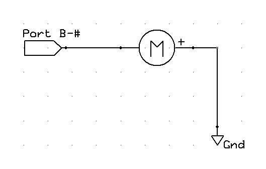
To turn on the motor, I set the port’s value to 1 (setbit). This made the port output +5V, causing power to flow from the pin through the motor to ground. (Engineers, pardon me for using positive current flow, but there’s no point in getting into that much detail in this class.) The motor spun, but weakly.
Active Low
Next, I tried a configuration called “active low,” in which you set the chip’s pin to a low voltage to make the motor active. To set this up, I wired the motor from the pin to the +5V power connection, instead of to ground.
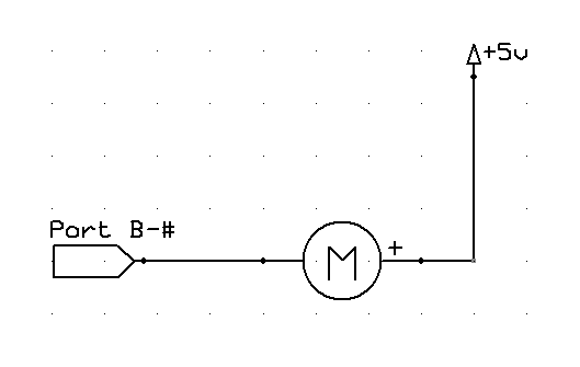
Then to activate the motor, I set the port’s value to 0 (clearbit), so that the pin’s voltage dropped to 0 and power was coming from +5V through the motor to the pin. The motor spun much faster, demonstrating that the chip is able to sink more power than it can source.
Transistor Driver
Finally, I tested using a separate transistor to power the motor. I had a suspicion that even though the motor ran faster in an active-low configuration, I might be able to get yet more performance using a separate transistor.
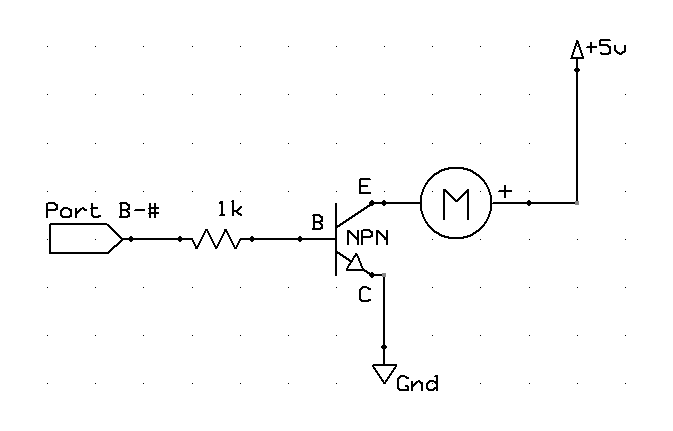
In this circuit, the LogoChip port goes high (+5V) and sends a small current (5mA) through the base-collector (B-C) junction of the NPN transistor. The transistor has a beta (amplification factor) of about 200, so that permits an emitter-collector current (E-C) of about 1A–enough that I’m pretty sure the transistor is in saturation, even though I haven’t checked the datasheet.
In non-geeky-electronics terminology, the transistor is working like a relay. A small amount of power through the relay coil controls a large amount of power through the relay’s contacts. In the case of the transistor, one wire (the collector) is shared between the low-power coil circuit and the high-power contact circuit. All the stuff with the numbers is just calculating the right value(s) of resistor(s) to use based on your circuit and the characteristics of your transistor.
And it worked as expected. The motor spun noticeably faster with the transistor driver than it did even in the active high configuration.
Stuff for Steve
I dug a couple of salvaged transistors and resistors out of my parts bins, soldered longer leads onto them, and brought them to work today for Steve to try out. I’ll be interested to see how much difference it makes for his motor. And like Tom McGuire, I have plenty of stuff saved up, so the offer’s open to anyone in class if you need help with circuits or components.