The Wiring
Sunday, worked in around the community orchestra concert, I got the stepper motor moving using my old friend, the 754410 dual H-bridge driver. I hooked each coil across an H-bridge, and used my Curiously Strong LogoChip as a controller, with two pins running each bridge (forward and reverse). Four pins per motor may or may not be the best way to build a complete CNC machine, but it worked nicely for testing.
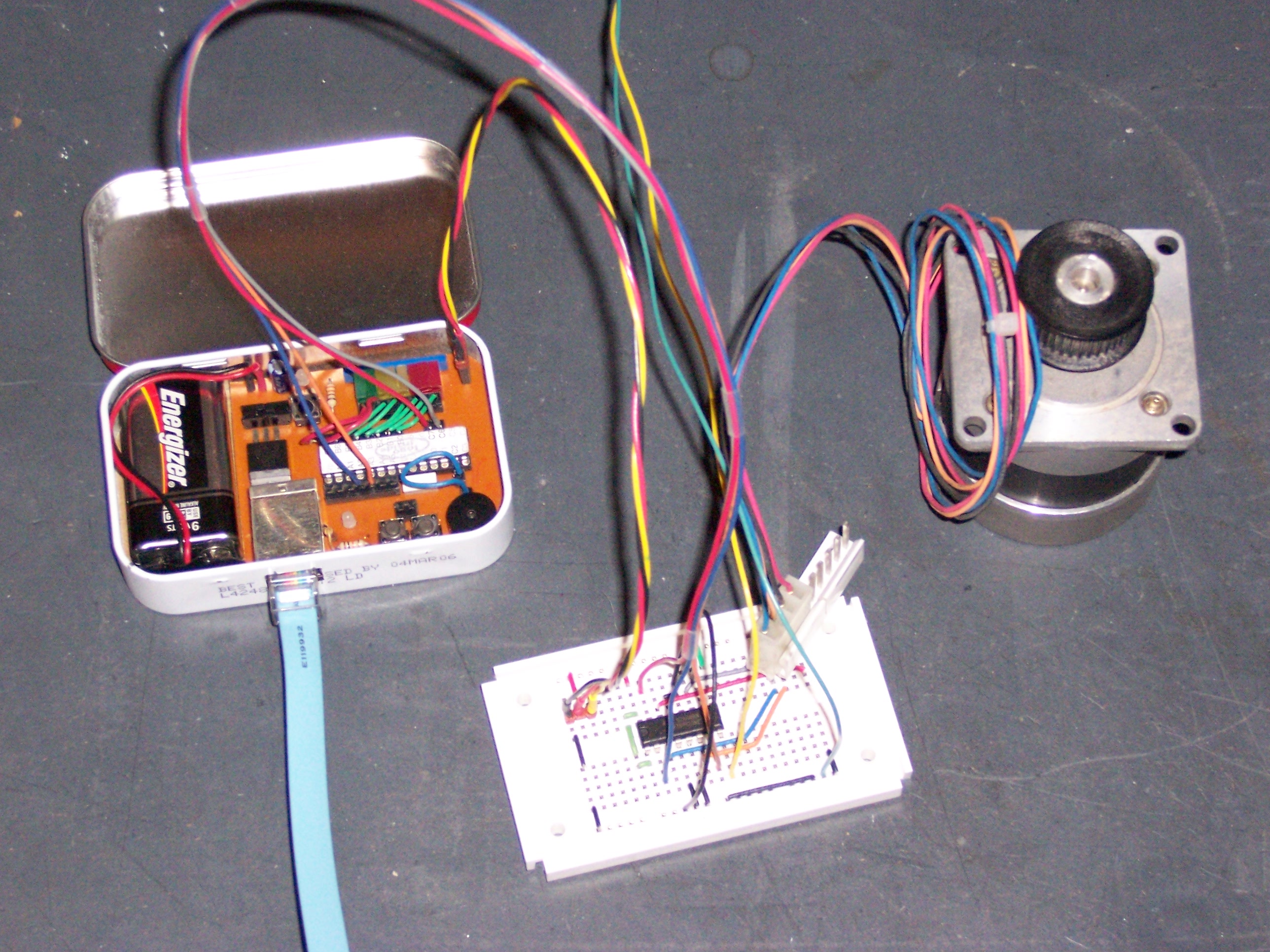
The red/yellow/black wire set from the LogoChip to the driver board provides regulated 5V and unregulated 9V to any auxiliary circuits I want to connect–I like to think of it as the PTO. The red/grey/blue/orange wires from the LogoChip to the driver board are the step control signals, and the red/black/blue/orange wires are permanently cabled into the motor. The yellow/green wires feed from one of the variable outputs on my bench power supply, and provide drive power separate from logic power, to keep dips and noise due to the motor from interfering with the logic control circuitry.
The Software
After wiring up the driver board, I wrote a little LogoChip program to control the driver. I needed to provide a quadrature-encoded signal (one goes high, two goes high, one goes low, two goes low) on two sets of two pins, and be able to reverse it. It turned out to work really nicely to modularize the CW/CCW quadrature code in one function, and put the icky code to deal with turning pins on and off in a separate function–it makes the quadrature code reusable to run multiple motors, among other things.
Here’s what I ended up with:
- stepper.txt – Program to drive bipolar stepper motor
Here’s the code:
;   stepper.txt
;
;   06-May-2006  Keith Neufeld
;
;   Test/drive bipolar stepper motor, using external 754410 driver chip.
;   Two coils are driven in quadrature:
;
;       ===|       |=======|       |=======|       |=======|
;          |       |       |       |       |       |       |
;          |=======|       |=======|       |=======|       |===
;
;       =======|       |=======|       |=======|       |=======|
;              |       |       |       |       |       |       |
;              |=======|       |=======|       |=======|       |

;------------------------------------------------------------------------------
;   Debug system
;------------------------------------------------------------------------------

constants [[debug 0]]
;constants [[debug 1]]

;------------------------------------------------------------------------------
;   Section to manipulate stepper motor.
;   Coil 1 driven by C7/C6.  Coil 2 driven by A2/A3.
;------------------------------------------------------------------------------

constants [
    [coil1-port portc] [coil1-ddr portc-ddr]
    [coil1a-bit 7] [coil1b-bit 6]

    [coil2-port porta] [coil2-ddr porta-ddr]
    [coil2a-bit 2] [coil2b-bit 3]
]

to stepper-off
    clearbit coil1a-bit coil1-port      ;   set all coil outputs low
    clearbit coil1b-bit coil1-port

    clearbit coil2a-bit coil2-port
    clearbit coil2b-bit coil2-port
end

global [steps-per-sec msec-per-step]    ;   timing "constants"
global [coil1-pos coil2-pos]            ;   current coil state

to init-stepper
    stepper-off                         ;   shut down all coil outputs

    clearbit coil1a-bit coil1-ddr       ;   set all coil pins as outputs
    clearbit coil1b-bit coil1-ddr

    clearbit coil2a-bit coil2-ddr
    clearbit coil2b-bit coil2-ddr

    setsteps-per-sec 2                  ;   2 steps per second
    setmsec-per-step 1000 / steps-per-sec       ;   precalculate wait per step

    setcoil1-pos 0                      ;   initialize quadrature to (0,0)
    setcoil2-pos 0
end

to step-set                             ;   push out new quadrature values
    ifelse debug [
        send 48 + coil1-pos             ;   0/1 with no CR
        send 32                         ;   space with no CR
        print coil2-pos
    ] [
        ifelse coil1-pos [
            clearbit coil1b-bit coil1-port      ;   clear before set
            setbit coil1a-bit coil1-port
        ] [
            clearbit coil1a-bit coil1-port      ;   clear before set
            setbit coil1b-bit coil1-port
        ]

        ifelse coil2-pos [
            clearbit coil2b-bit coil2-port      ;   clear before set
            setbit coil2a-bit coil2-port
        ] [
            clearbit coil2a-bit coil2-port      ;   clear before set
            setbit coil2b-bit coil2-port
        ]
    ]
end

;   CW pattern:
;       0110.0110
;       0011.0011

global [new1 new2]                      ;   temps for coil values

to step-cw
    setnew1 not coil2-pos
    setnew2 coil1-pos

    setcoil1-pos new1
    setcoil2-pos new2

    step-set                            ;   do it
end

to step-ccw
    setnew1 coil2-pos
    setnew2 not coil1-pos

    setcoil1-pos new1
    setcoil2-pos new2

    step-set                            ;   do it
end

;------------------------------------------------------------------------------
;   Routines to tie it all together
;------------------------------------------------------------------------------

to init-all
    init-stepper
end

to powerup
    init-all
end

to startup
    init-all
    loop [
        step-cw
        mwait 100
    ]
end
The Movement
I started up the motor control with a loop [ step-cw wait 10 ] from the LogoChip console, then turned up the variable power supply until the motor was chunking along at a step per second. That channel of my power supply is only good for 1.5A, and I found that no matter how high I turned the dial, the meter didn’t read any higher than about 2.5V. I guess the coil power calculations were pretty close.
Next, I played with different timing values, to watch the motor turn at different rates and test its torque. I found that on this power supply, I could very easily stop or spin the motor contrary to the control signal. That was a little disappointing, but I realize also not at all a fair test, with the motor so underpowered.
Finally, I knew the 754410 is only rated for 1A per bridge, and I was attempting to use it for much more than that. I was being careful not to sustain high-voltage testing for long periods, but I was still curious how the 754410 was reacting thermally. The result was fascinating–I could quite distinctly feel the chip getting warmer as I ran the motor and cooler when I stopped it. I’m used to components heating up, but I’ve never before experienced it so directly in real time (at least, not without scorching my fingers).
I had known that the 754410 wouldn’t be my ultimate drive circuit, but I hadn’t known I would hit the wall with it so quickly. After realizing how hot it was running, I knew the next step was building a drive circuit with discrete power transistors. And I just happened to have some on hand: MOSFETS, from the stepper drivers in some old printers.
Review time in my Malvino–quite possibly the best $130 I ever spent.
mate, where did you get up to with this?