Passing behind a church-operated thrift store a month or two ago, I saw a black bakelite box in the area where they discard stuff they don’t want, about to get rained on. After seeing that it was a metronome, I rescued it and made it mine. This weekend I tried it out for the first time and ended up repairing the motor. The motor’s workings were unfamiliar to me, but its repair was self-evident.

Oh, and I cleaned it up a bit, too.
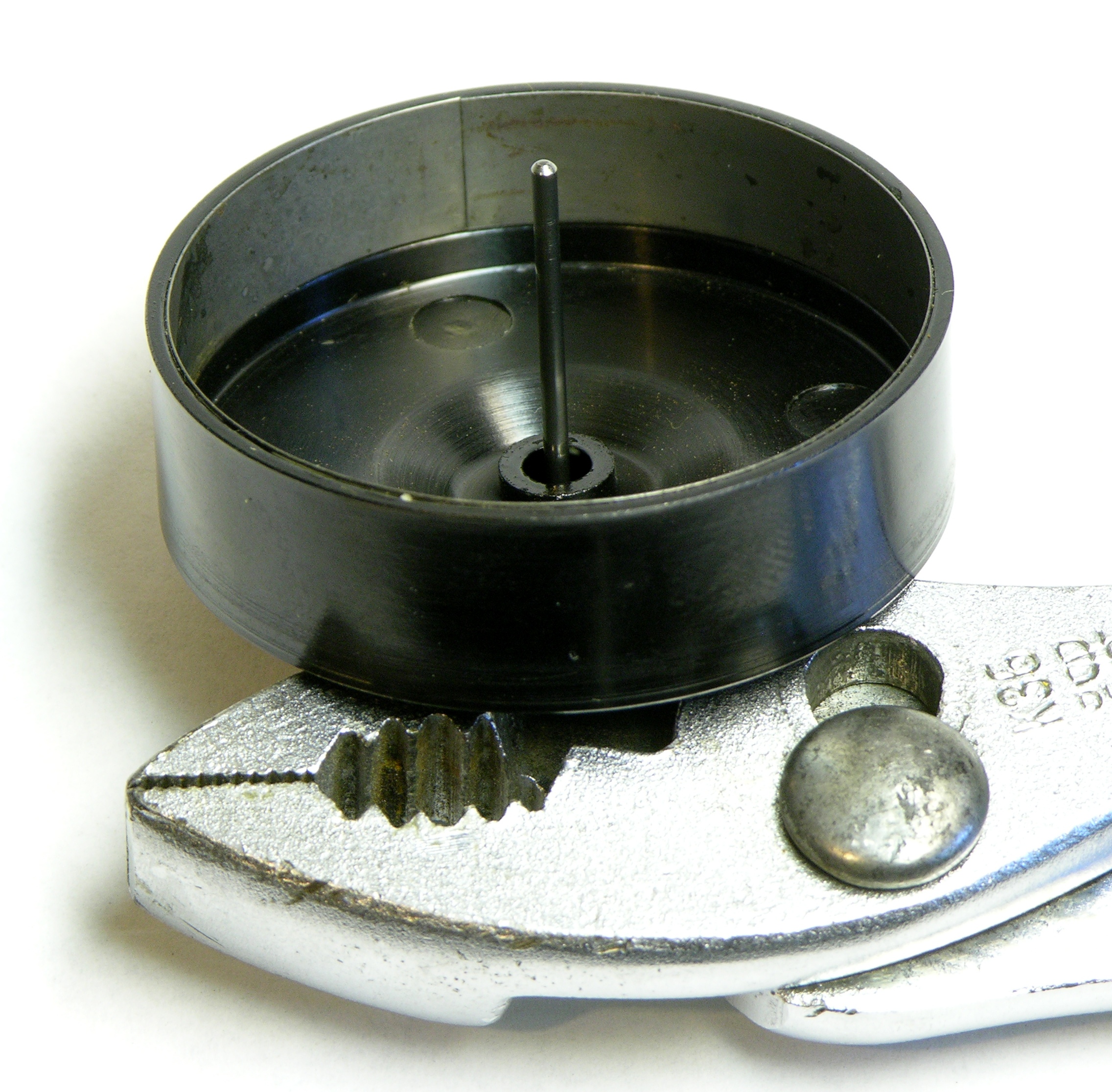
Starting on the inside and working my way out, the rotor has a metal band around the inside of the shell, and one end of the band had sprung so it was no longer sitting flush like it is again after the repair. That end was sticking out far enough to catch on the stator, so the motor didn’t turn.
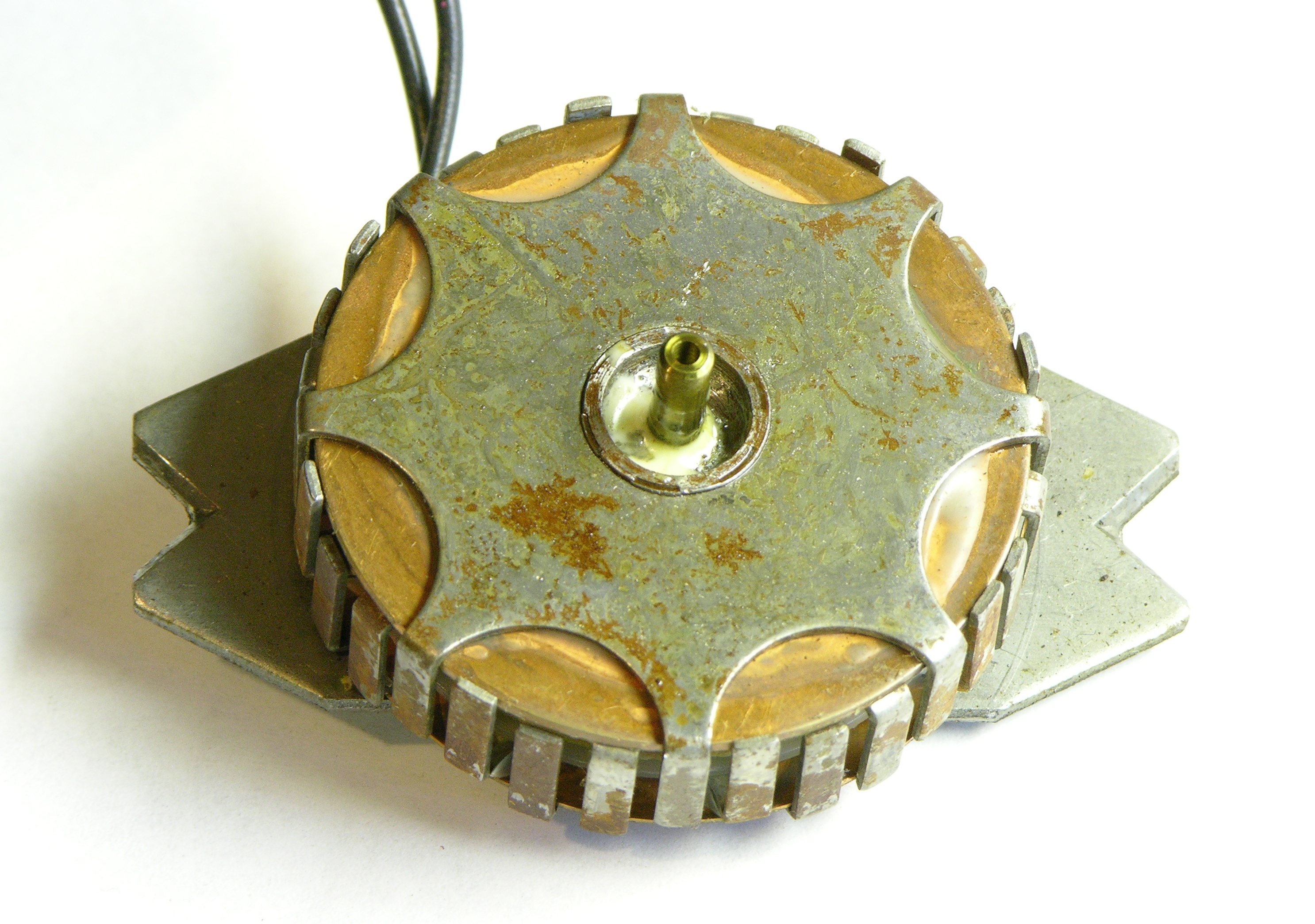
The rotor fits around the stator, which is powered directly by 120VAC. I don’t understand at an electromagnetic level how this motor works. If you do, explanations in the comments are always welcome.

The outside of the rotor is shaped like a Hershey’s Kiss ™, to form half of a variable transmission.

The motor is mounted with the point facing down (in normal operation) and gravity pulls the rotor away from the stator to engage with the rubber roller.
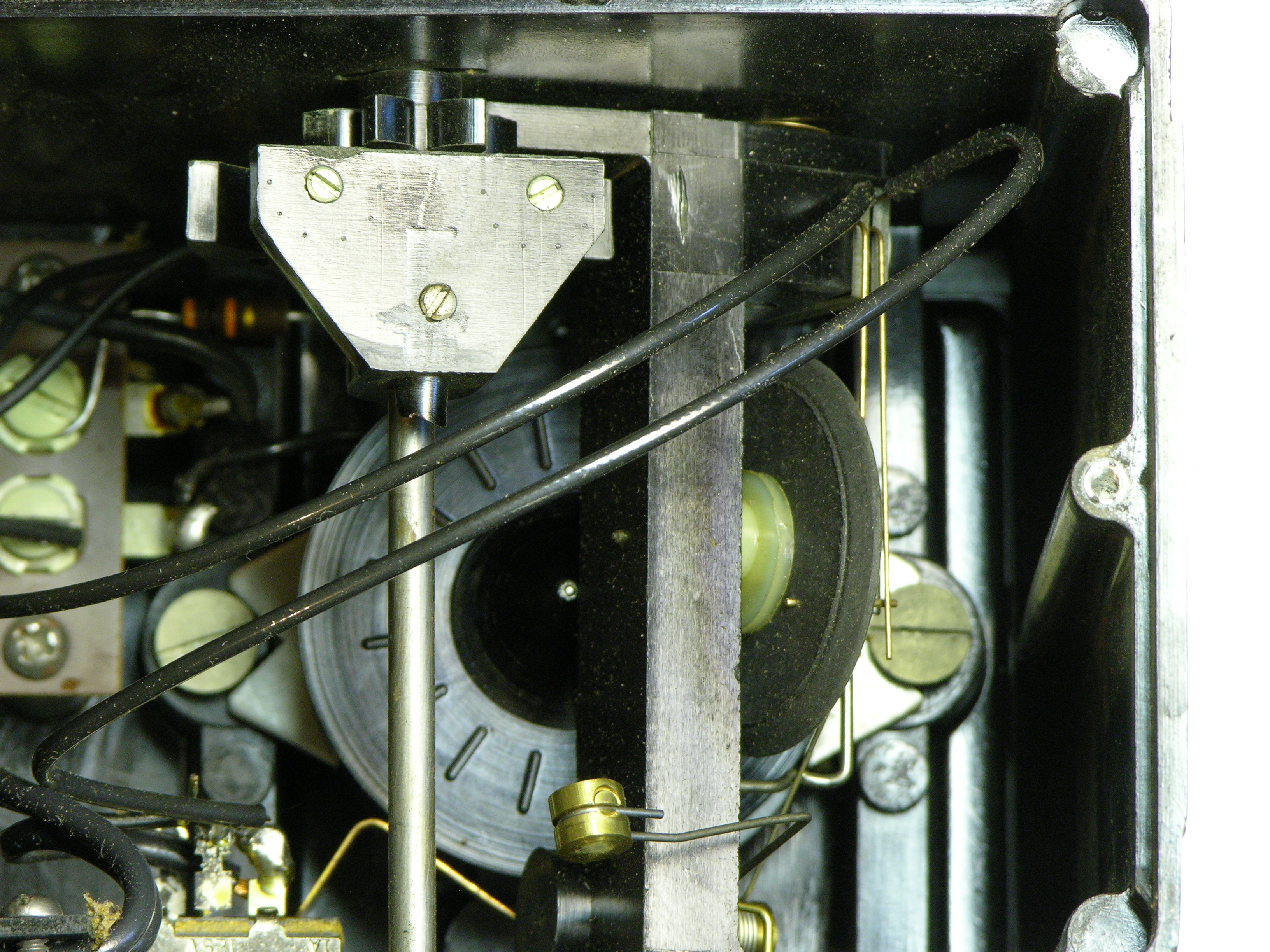
The rubber wheel’s axle has a cam to make and break the contact wires that flash the neon lamp in the top of the metronome, as well as to strike a small clapper weight against the back of the metronome case when the metronome is set to audible. The tempo knob on the front rotates this portion of the transmission to make the rubber wheel contact the rotor on the wide part of the cone for a fast tempo
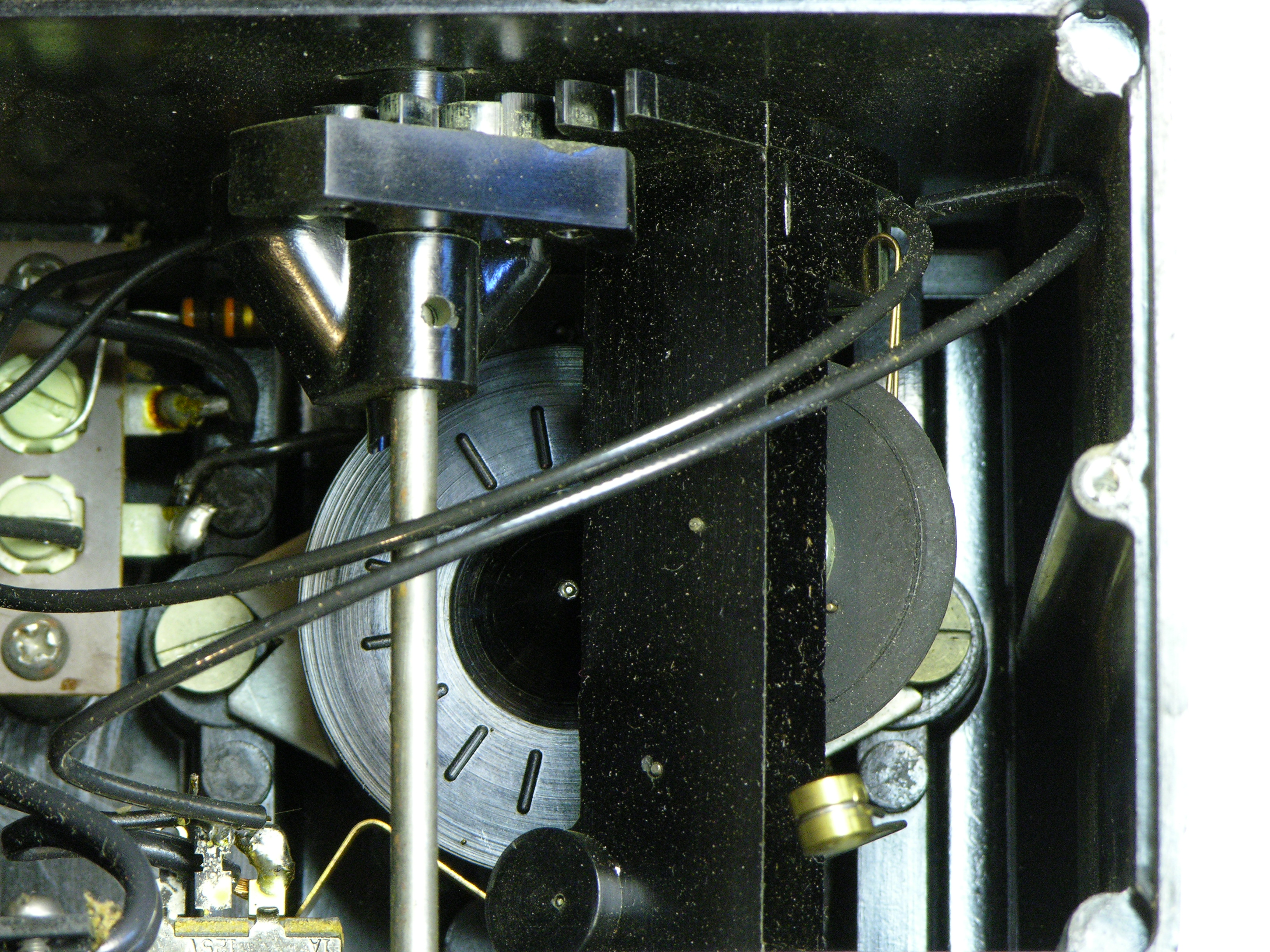
or on the narrow part for a slow tempo.

The switch turns on the AC supply to the motor. It also presses a wire brake against the rotor when in the off position, presumably so that one doesn’t have to suffer through one or two extra strikes of the metronome when switching it off. Such attention to detail!
The small knob on the left engages and disengages the clapper mechanism from the rubber wheel’s cam.
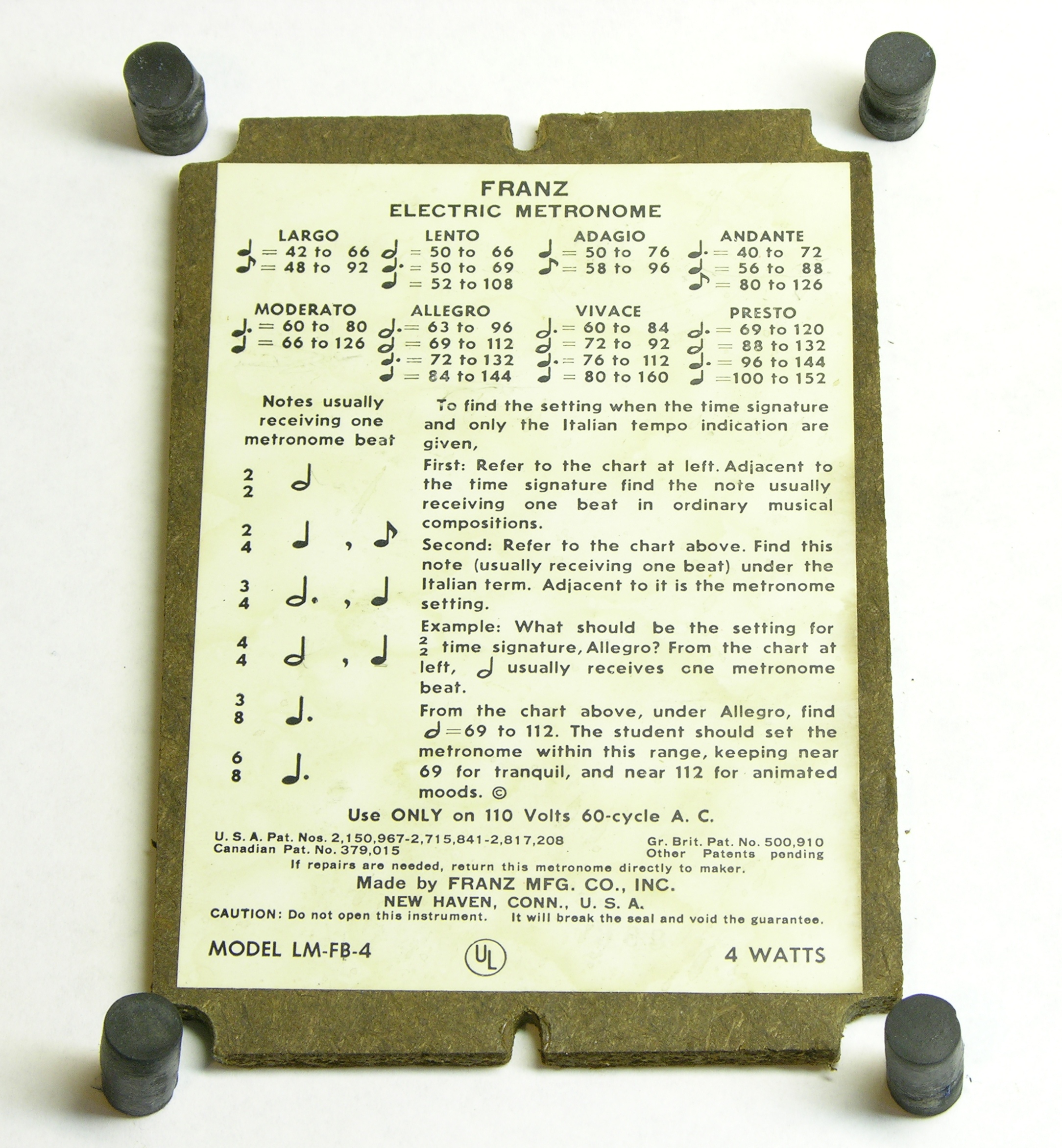
The case bottom thoughtfully includes an interpretation of tempo markings to beats per minute.
Note the rubber feet.
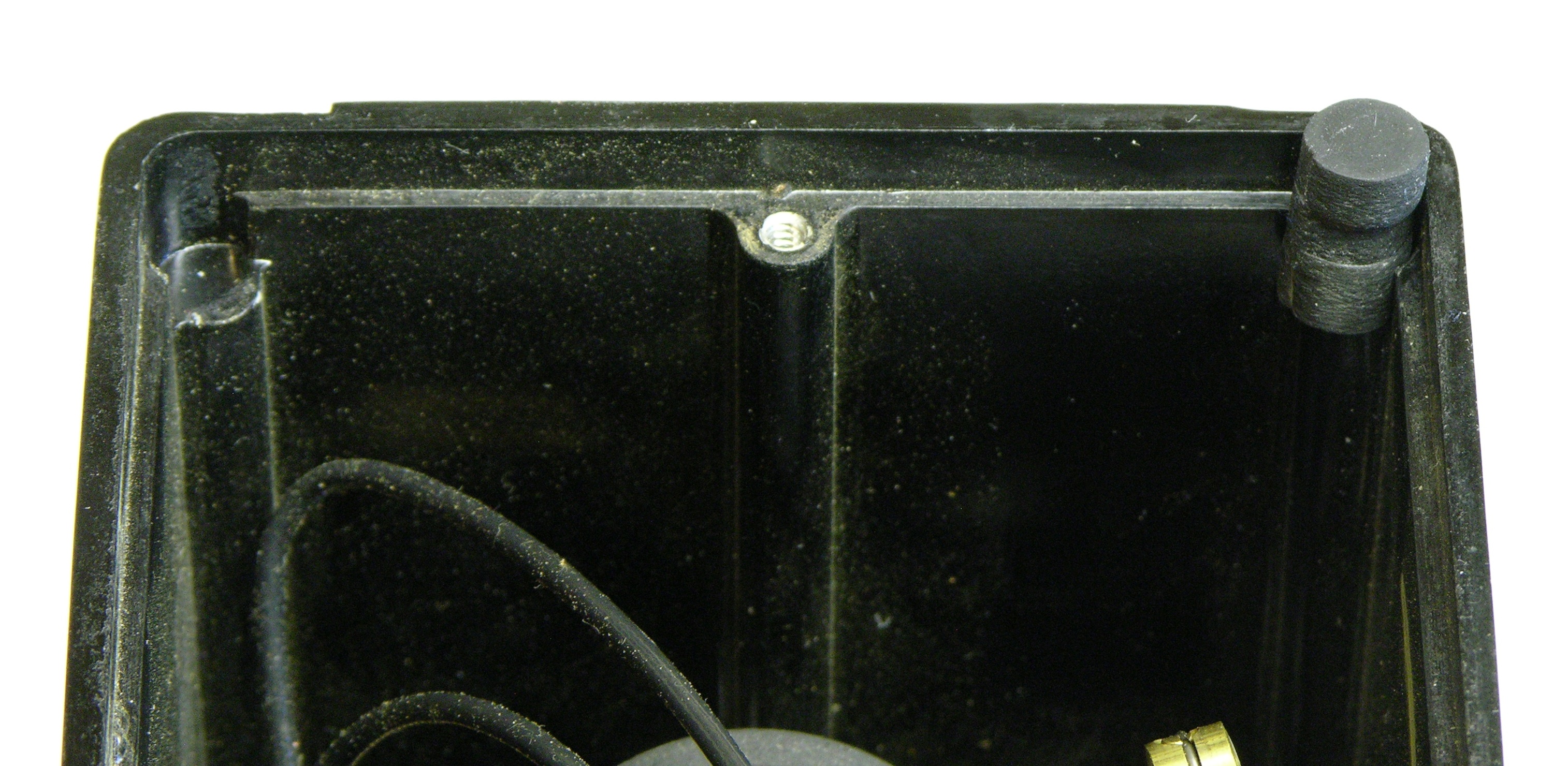
Instead of relying on adhesive or screws, they’re little cylinders held captive by their own elasticity between the cutout corners of the case bottom and recesses in the corners of the case. I’ve never seen that before and I find it delightful.
Et voila! It works, and appears to keep pretty good time. I’m already using it to practice a Scarlatti sonata, to smooth a section where the fingering is giving me fits. Trés bien!
I hope you realise you’ve voided the guarantee now–according to the label.
–Philip.
Philip — au contraire! I’m quite certain I didn’t break any seal.
Looks to be some form of induction motor, although reversed from the more traditional design, with the field portion in the center and what’s normally the armature being the outer part. Looks to be an 8 pole design, with the coil located in the center of the stationary part, and the pole pieces formed by the steel slotted section brought out and folded over.
The interesting thing to check would be whether the metal
band on the outer, rotating piece has a permanent magnetic
field or not, thus differentiating it from an induction motor,
and making it a permanent magnet, synchronous motor (although synchronous motors tend to not be self starting, especially on single phase excitation, thus usually requiring an induction motor component to get them up near synchronous speed, where they can then lock into synchronous speed; but, I see no real reason why they’d need a synchronous motor with the design of the device). I can’t really tell what that band is composed of from the photographs.
The part I’m not sure about, though, is that I’m not sure what all of the fingers do. My initial thoughts are that they function similar to the shaded poles on a shaded pole induction motor, but I can’t make out enough detail to be sure.
As you may remember, an induction motor produces a rotating magnetic field, which induces a field into the opposite part, which then causes it to be dragged around. However, with a single phase excitation, the field produced just pulsates without rotating, unless some trick is used.
There are, of course, several tricks which can be used. One is to use an auxiliary winding to excite a set of poles, and to provide excitation to this auxiliary winding by a phase shift of the current (either a leading component, produced by a
capacitive phase shift, or a lagging component, produced by an inductive phase shift). The auxiliary winding can only be used when starting the motor (e.g., start winding), or can be used all the time when the motor is in operation (e.g., run winding).
But, since this example only shows two wires going to the coil (and, one presumes, only one coil), then this technique isn’t being used. Another trick involves “shading” a portion of some of the poles, usually by wrapping a piece of Copper or other highly electrically conductive metal around the portion of the pole, which produces a slight phase shift to the magnetic field, giving the illusion of a rotating magnetic field. That might be what’s being done here, but it’s hard to tell, since I can’t see where/what all of the fingers are connecting to.
In any case, with this being an 8 pole motor, the rotation speed should be a little less than 3600/8 RPM (if I’m remembering my induction motor theory correctly [1]), when used with a 60 Hz excitation. That gives a figure of a little less than 450 RPM for the rotor, with the difference being due to the “slip”, which should be fairly small, given that the motor is only lightly loaded.
[1] It’s been a LONG time since I studied induction motors, so take what I’ve said with a grain of salt.
Dave
The motor is one of these http://en.wikipedia.org/wiki/AC_motor#Slow-speed_synchronous_timing_motors