The Board
This week, I laid out the schematic and board design for one digit of the display. The circuit and board are designed so that the colon and decimal at the right edge can be omitted for the left digit of each pair and the rightmost digit of the whole display (88:88.88), with no impact to the rest of the LEDs.
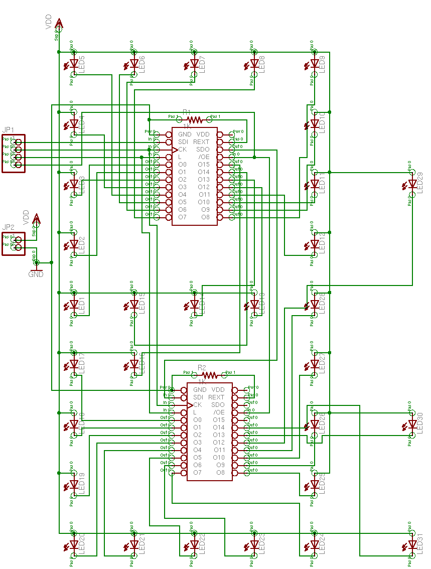
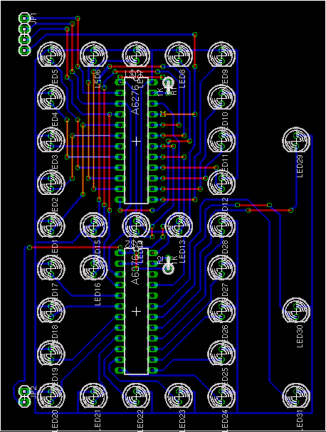
Through great hubris, I became convinced to place the driver chips physically within the two loops of the digit. For the lower loop, this posed no great challenge, as the LED numbering sequence and driver pinout both run counterclockwise. For the upper loop, however, the board got pretty ugly–exacerbated by my plan to use a single-sided board. I drew it as a two-sided board, but the top side is really going to be jumper wires. And as close together as they ended up (.05″ in most places), I’m going to have to leave the insulation on. Ah, well. At least it offers a lovely opportunity for color-coding: red and black for power, blue for LED lines, sum’n’ else for signal wires.
The Mock-Up
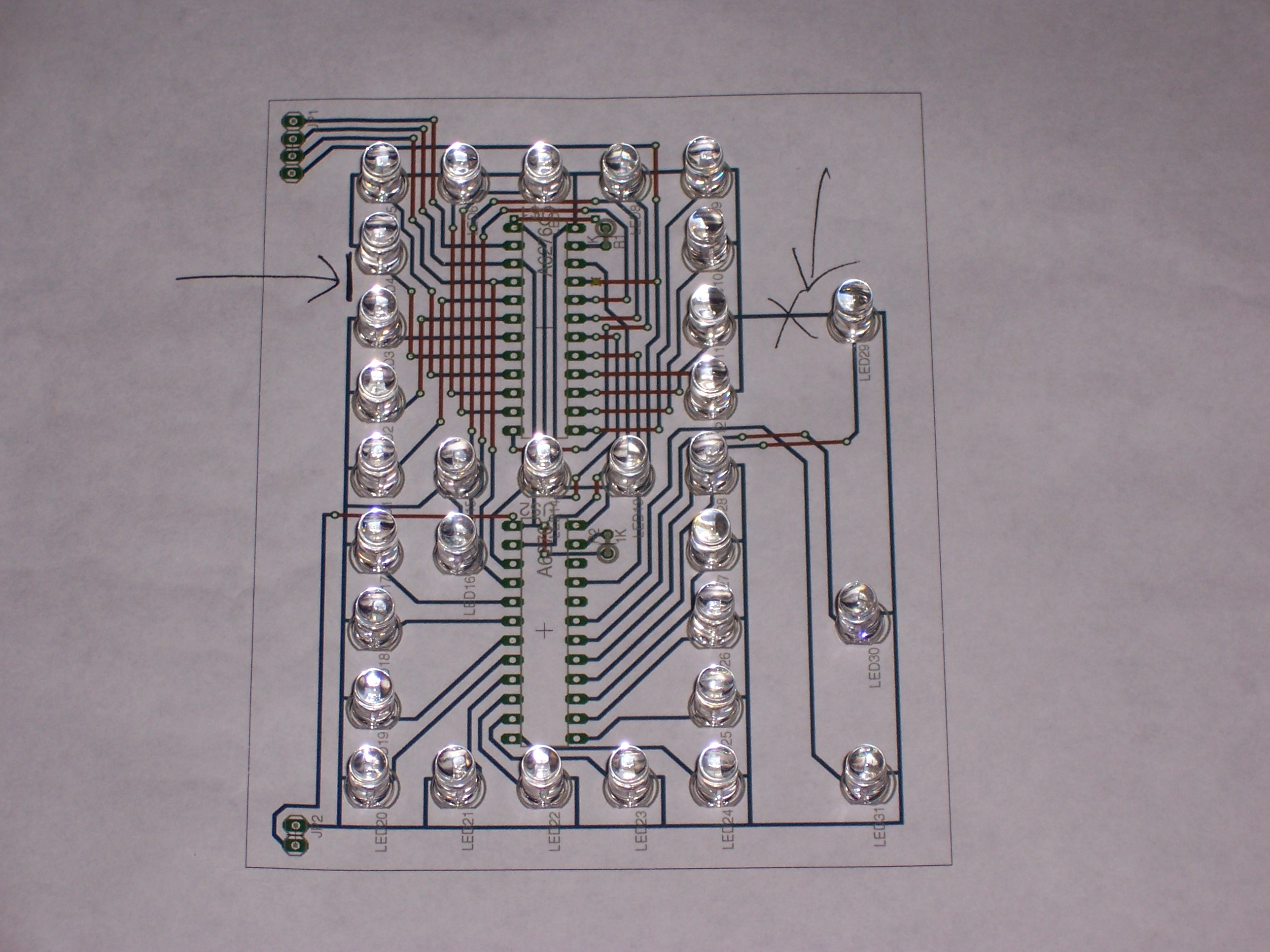
I printed out the PCB layout and took it to Jeremy’s this week, and I think he was a little surprised at its visual complexity. I can see that it may look intimidating, but it really wasn’t that bad to do–schematic first, where the connections are obvious; and then the schematic automatically populates the board with components and “ratlines” (or “airwires”–temporary connections identifying traces that need to be made), which you just move wherever you want them.
The real reason I took it to Jeremy, though, was that it’s the first visual indication of what the LED spacing is going to look like. I’m concerned that they’re going to be too far apart, and I’m going to have to redesign the board with the driver chips on a back-side daughterboard. And unfortunately, it’s going to be really hard to know for sure until we see a prototype in operation–which is why I’m drilling a board with Joel this afternoon.
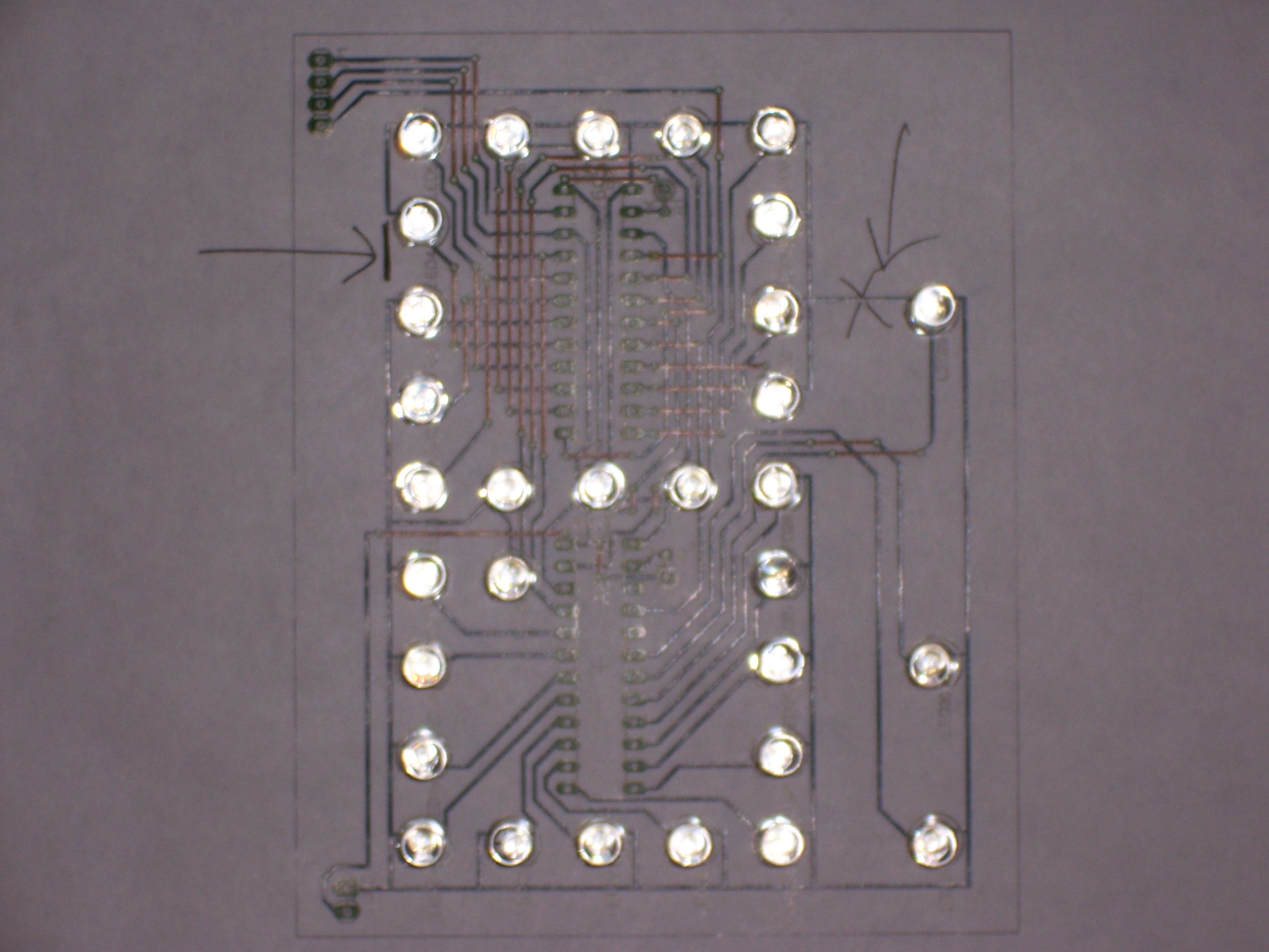
Meanwhile, I couldn’t resist populating the printout with my new LEDs. (The hand-drawn arrows are notes to myself about corrections to an early version of the board.)
And the LEDs are reflective enough that a flash picture from directly above begins to give an idea what the board may look like when illuminated–although the reflection is white, and the LEDs of course shine blue when lit.