As I noted previously, I recently got a x0xb0x kit. The x0xb0x is an open-source-hardware replica of the 1980s Roland TB-303 bassline synthesizer (and sequencer) that was influential in the development of acid house music. Limor of Adafruit Industries and a mysterious, anonymous German studied the TB-303 schematics and measured the behavior of its now-rare semiconductors and designed a replica with the same analog circuitry and new digital features, including MIDI I/O (supplementing Roland’s pre-MIDI “DIN sync”) and simpler sequencer programming.

Adafruit produced x0xb0x kits in batches of 100 as Limor was able to track down enough “rare parts,” order circuit boards, and assemble the common parts into kits. I’d been on her waiting list since 2008, so was terribly disappointed when she officially announced what we had all come to realize anyway — that tracking down the rare parts was becoming enough of a hassle, she wasn’t having any fun doing it and wasn’t going to produce any more kits.
Happily, Limor announced shortly thereafter that thanks to Adafruit’s open-source hardware license, James Wilsey of Willzyx Music in Taiwan has taken up the torch and would shortly be offering x0xb0x kits.
I browsed the Willzyx web site and saw an Express Kit with rare parts, circuit boards, and panels, but no case and common parts. I emailed James to thank him for making the kits available and ask whether he’d be producing full kits. He replied that he would shortly; and in spite of having a no-preorder policy, offered to hold one for me as soon as they were ready if I was interested.
I said yes, he soon told me that the kit was ready (even though the updated instructions weren’t yet), I sent payment, and he sent my kit, very nicely packed and with quick shipping and international tracking. James has been an absolute pleasure to deal with, pre-, mid-, and post-order.
What follows are a few notes from the build — not a time-lapse of everything all the way through, but things that struck me as unusual or interesting. All mistakes I made were my own fault for not waiting for the updated instructions.
Testing Each Stage
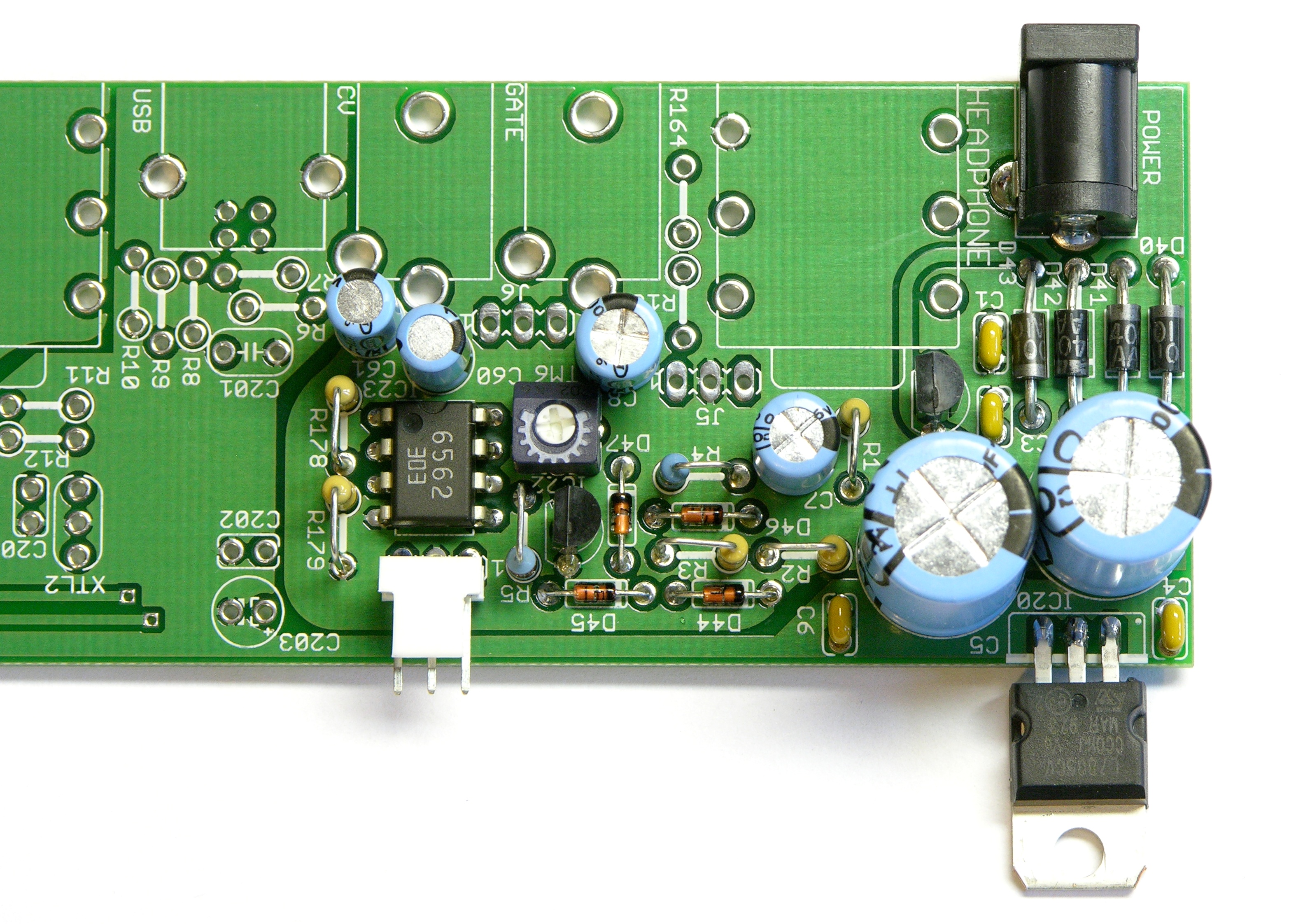
I’m just a bit too young to have assembled a Heathkit, so Adafruit’s instructions for the first several stages were novel to me — she identifies a section to assemble, then stops to have you test what you’ve just built. The power supply section, for example, includes notes for testing AC voltage and regulated DC voltage at two different points. Modular testing is a great way to make sure you don’t spend 40 hours putting your kit together and then have no idea why it doesn’t work.
Willzyx, by the way, provides sockets for all the ICs (which I hadn’t noticed when I soldered the op-amp above) and nice connectors for the inter-board jumpers (which I hadn’t noticed when I provided my own). Using his instructions will be much easier than desoldering these parts later.
Diffusing the LEDs
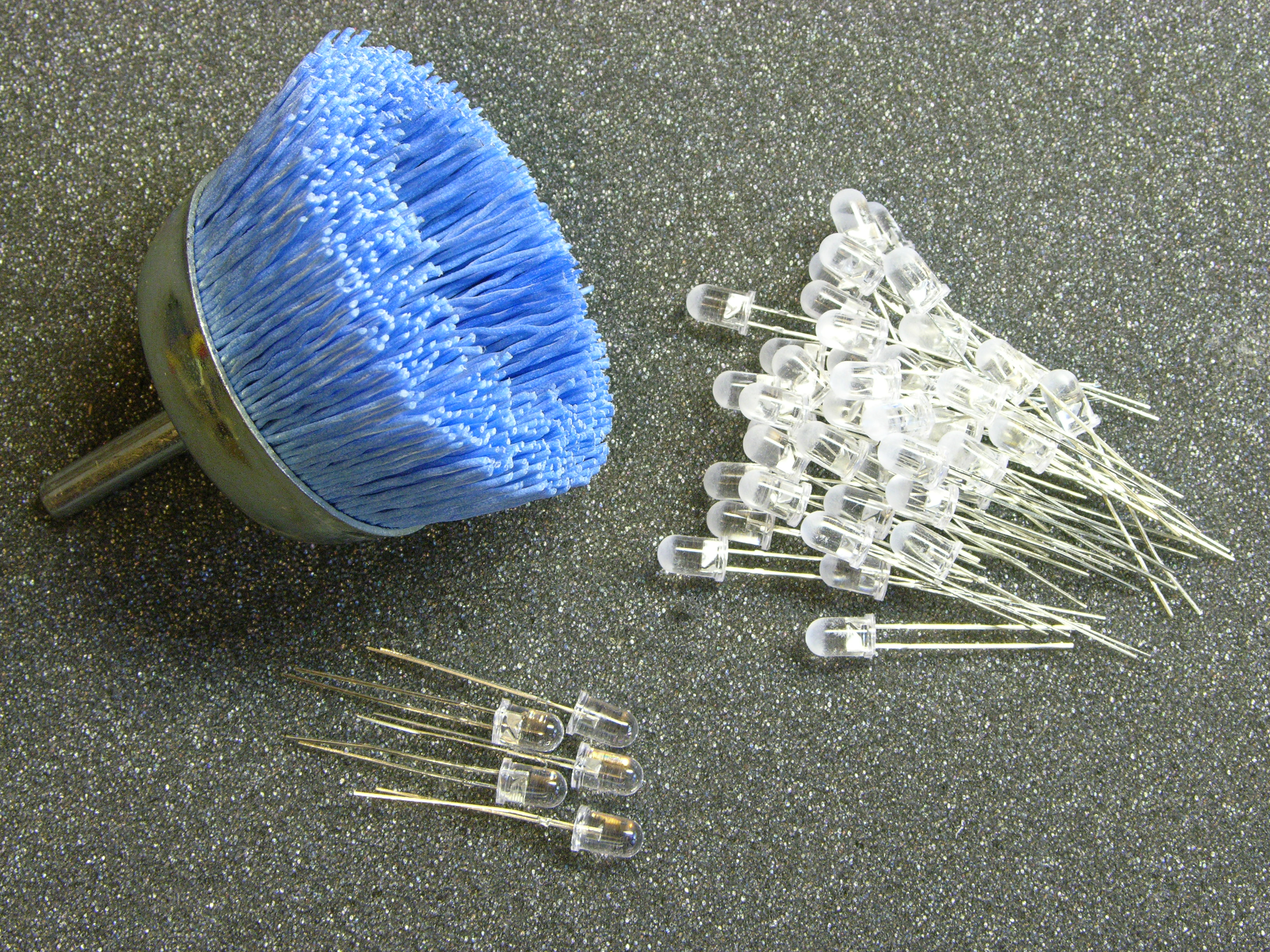
The kit includes high-brightness, non-diffused red LEDs. I don’t like the look of non-diffused LEDs, especially as panel indicators, because their low viewing angle makes them hard to see unless you’re looking at them dead-on (at which point they’re too bright). So I used my technique from four years ago (when I had just started the blog) and frosted them.
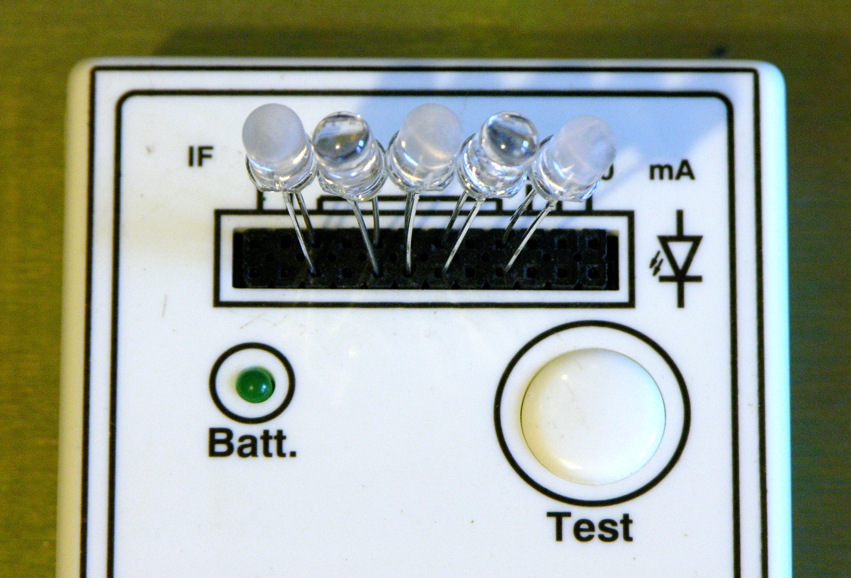
The diffused LEDs are noticeably translucent instead of water-clear like the unmodified originals.
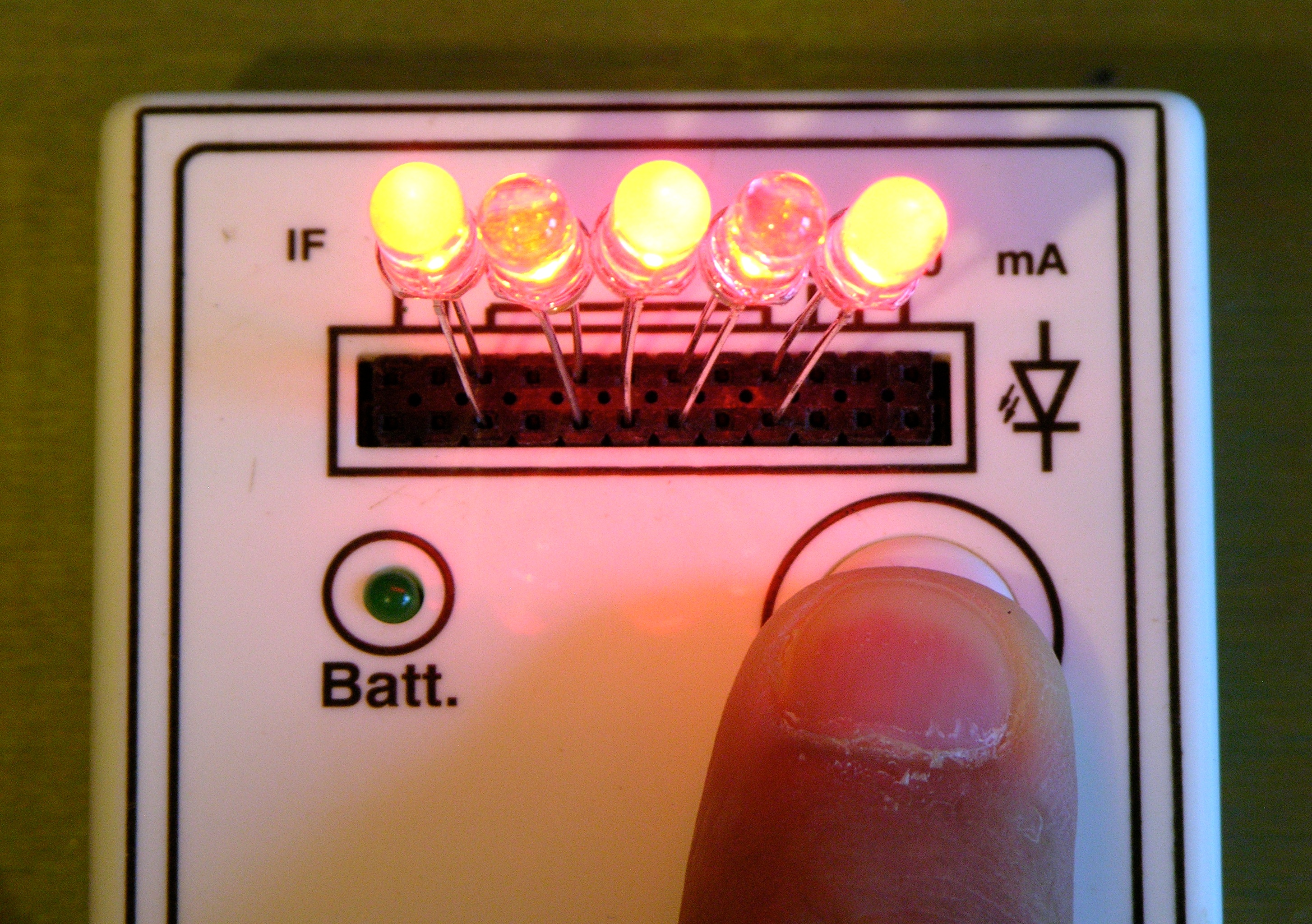
And they provide a nice, even illumination across wide viewing angles. (Note that they’re really quite red when you look at them with anything other than this camera.)
Once I had all the LEDs prepared, to solder them with proper alignment to fit the front panel, I inserted them in their standoffs and did the old trick of tack-solder one leg, then adjust the LED while reheating the joint. Then I put the front panel over the LEDs (further on than it actually fits in final assembly) to hold them all securely in position while soldering the cathodes and resoldering the anodes.
J3 Plug Goes on the I/O Board
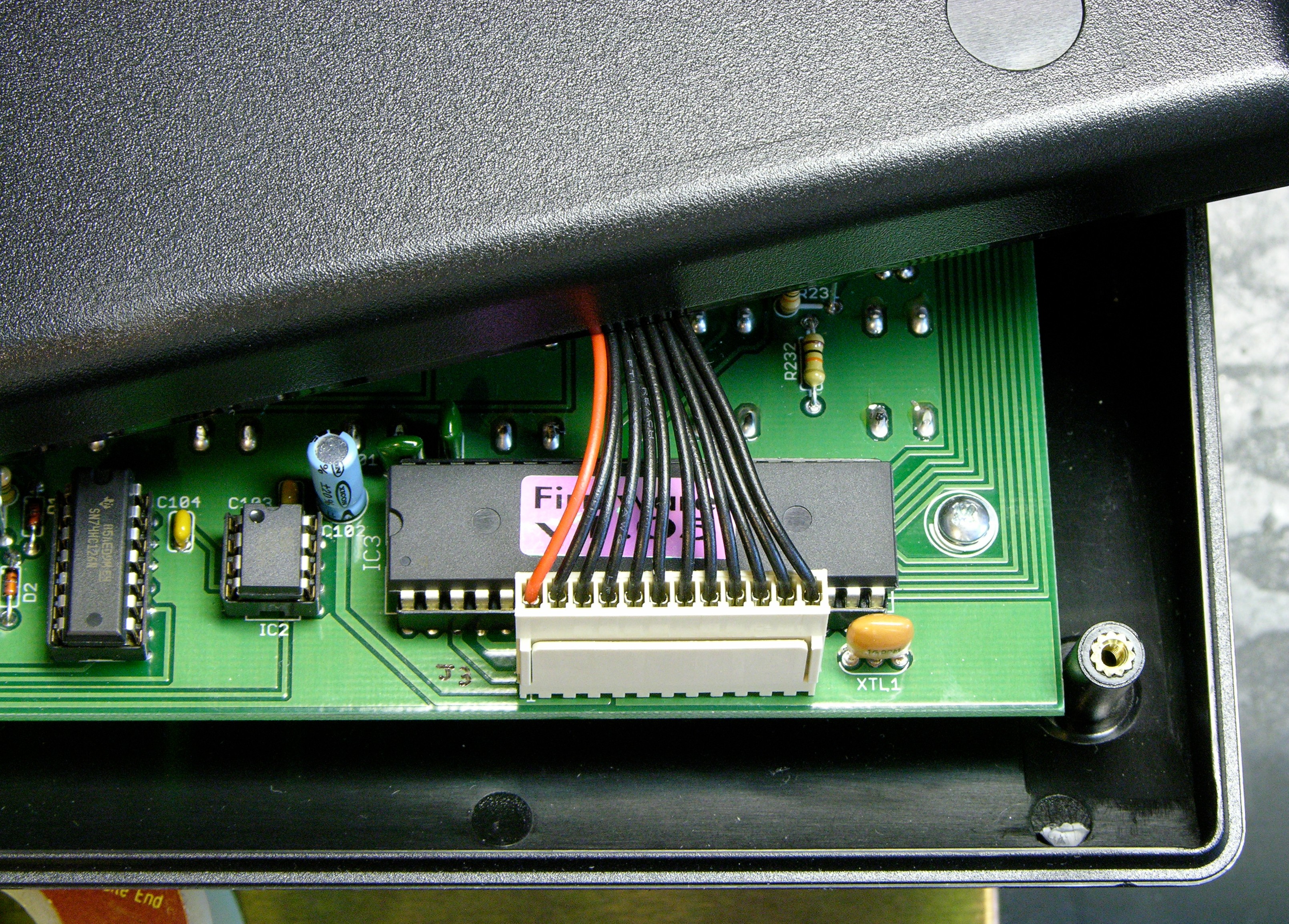
I had the x0xb0x nearly completed and ready to install all the cable bundles when I noticed that Willzyx provided wiring harnesses with a mating connector at one end to make servicing the x0xb0x easier. (The original kit just provided ribbon cables to solder at both ends.) Even after emailing James to confirm which board each plug was supposed to go on, I got this one wrong.
And when you get it wrong, the case doesn’t close. This is at the narrow front end of the case, and the connector is too tall. This was a nuisance to desolder and redo — but I ended up with tidier wiring the second time around, so it wasn’t all bad.
Shorten the Rotary Switch Shafts
The original Adafruit pre-assembly preparation instructions say to cut all the potentiometer shafts to the same length. Willzyx provides potentiometers that already have same-sized shafts (thank you!!!), so I disregarded this instruction — at my own peril.
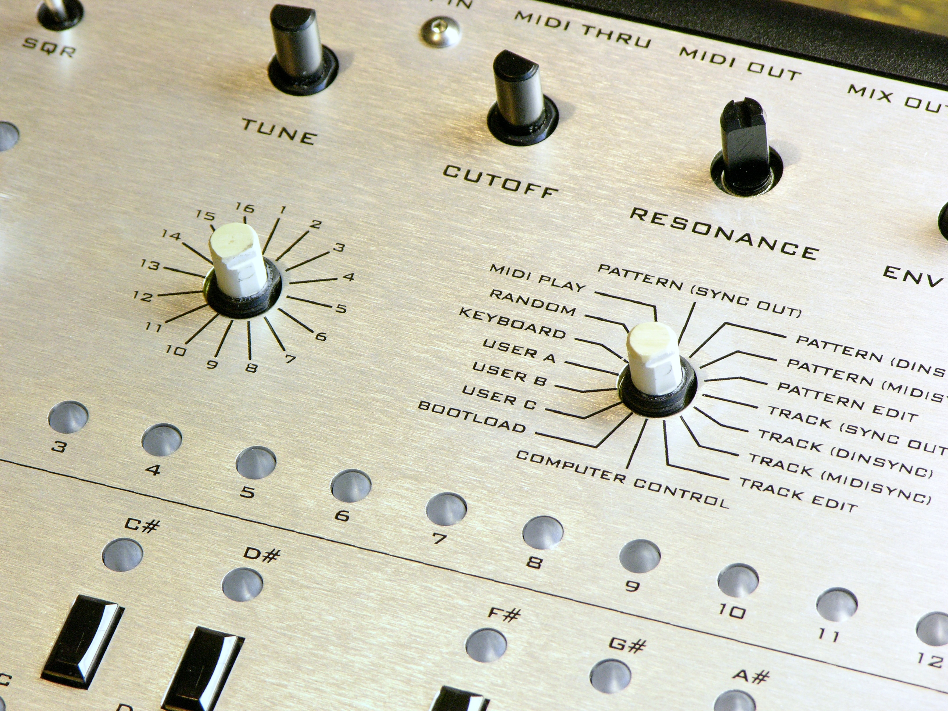
Yeah, the potentiometers all have same-sized shafts, but the two rotary switches have shafts way too long for the knobs to reach the ground. These would have been much easier to cut before installing. Just another case where the updated instructions will solve the problem for everyone else, and I should have looked at the parts more carefully since I knew I was building without up-to-date information.
Note that the flats on the shafts (which I refiled for the knobs’ set screws) are opposite the selected function. I powered it up to double-check before filing.
Done!

After two weekends of intermittent work, it’s done and 100% functional. I’ve been having fun this afternoon tweaking knobs to the bass line of “Sweet Emotion,” the most interesting one-bar pattern that I had stuck in my head. Thanks, Limor Fried and James Wilsey!
I have an LED tester just like that. I’ve thought it might be an interesting candidate for refitting with an EasyBright, because I think the marked current ratings are off for anything except red LEDs.
Use an EasyBright built for 20mA, 30mA, and 50mA? Interesting idea.
I assume you’d still want to be able to parallel LEDs within the same current rating like this cheap tester does. That gets more interesting, since the MAX16823 isn’t made for series-parallel operation — you’d get (about) half the current through each LED.
Why don’t you just hold out for my LED calculator? All I really need to finish it is a suitable case.
Hi I also bought a kit from James and am just nw finishing it up. /It was great to see your build and added info.
I was scouring the x0xb0x forums and noticed a lot of people are having trouble with dishonest dealers who are either outright taking their money or they are not happy with the parts they got in their kit. There seems to be only about 2 or 3 reputable places to buy a kit.
I guess it is important now more than ever to let potential builders know who they can get a good kit from and good support. James has been there for me just as you said pre, during, and soon to be post build as I just sent him a question yesterday. He has made this build go well with the detailed labels on all the parts and qualiy electronics. Willzyx is he place to buy a kit from(James).
Take care and keep the 303s cranked, I have 2 x0xb0x’s now… the kit was a bit tough at times (I am not new to kits and soldering electronics) the sound is perfecto! and true TB303 sound, it was worth my 40+ hours and the few aggrivations for this last one – Sam