This isn’t part of a normal x0xb0x build so I didn’t throw it into my build notes, but I had fun figuring out how to route and lace the x0xb0x’s wiring harnesses. I know lacing is overkill for this; but without some kind of cable management, the individual wires of each cable wouldn’t even stay together. Had the kit included ribbon cables, I wouldn’t have bothered.
Planning the Paths
Besides the obvious goal of keeping the wires tidy, my main goal was to position slack in the cables so that the back panel could be lifted out of the case and set to the rear, allowing full access to both circuit boards, without disconnecting anything.
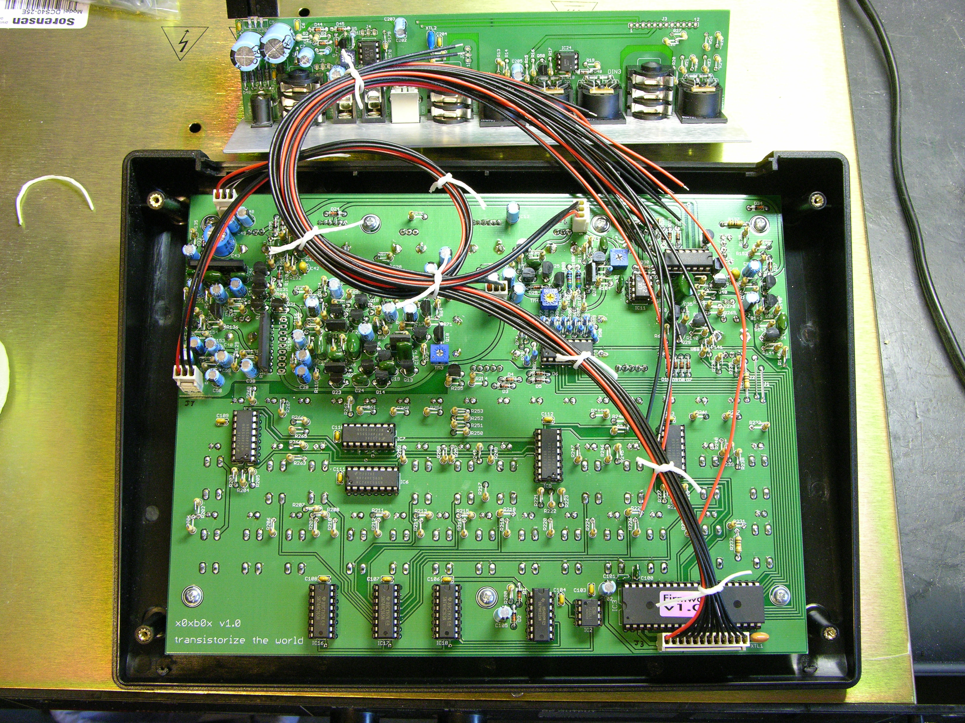
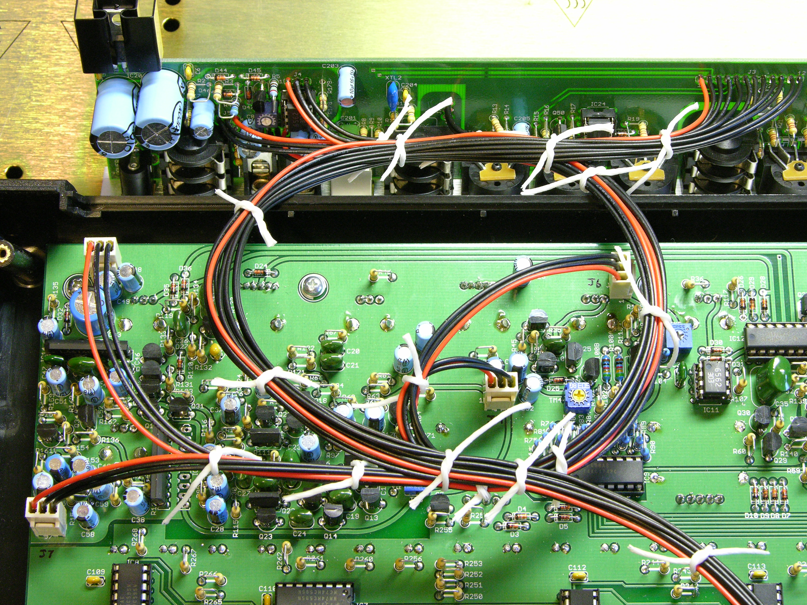
Before doing any real lacing, I mocked up the cable path to make sure everything would work. My first attempt, here, had enough length for the J3 bundle from the lower right of the main board to the right end of the I/O board; but J7′s wires coming from the left edge of the main board looped around too much before heading to the I/O board and didn’t reach their destination.
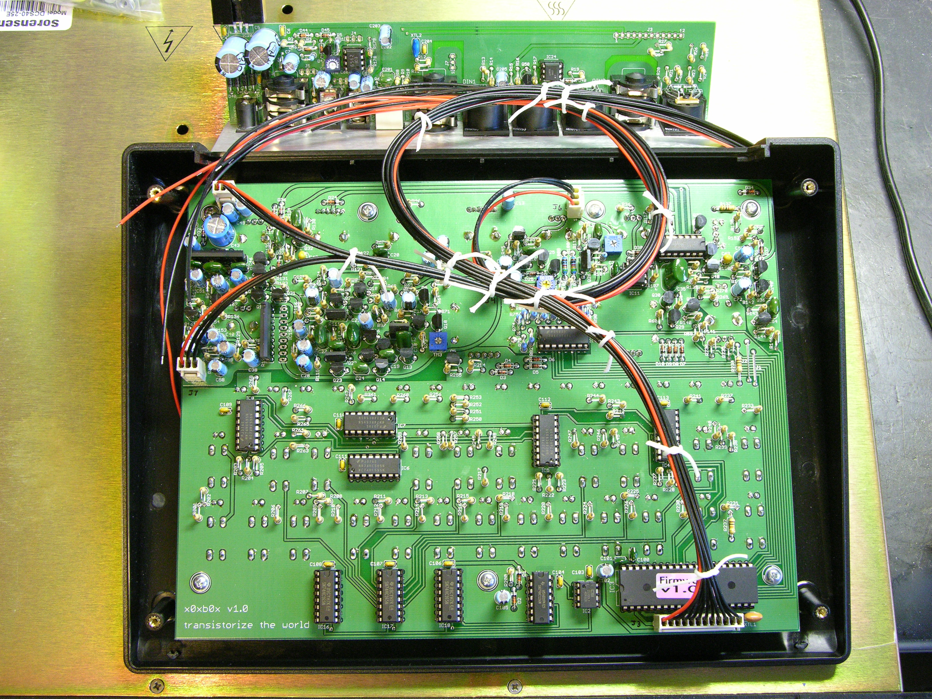
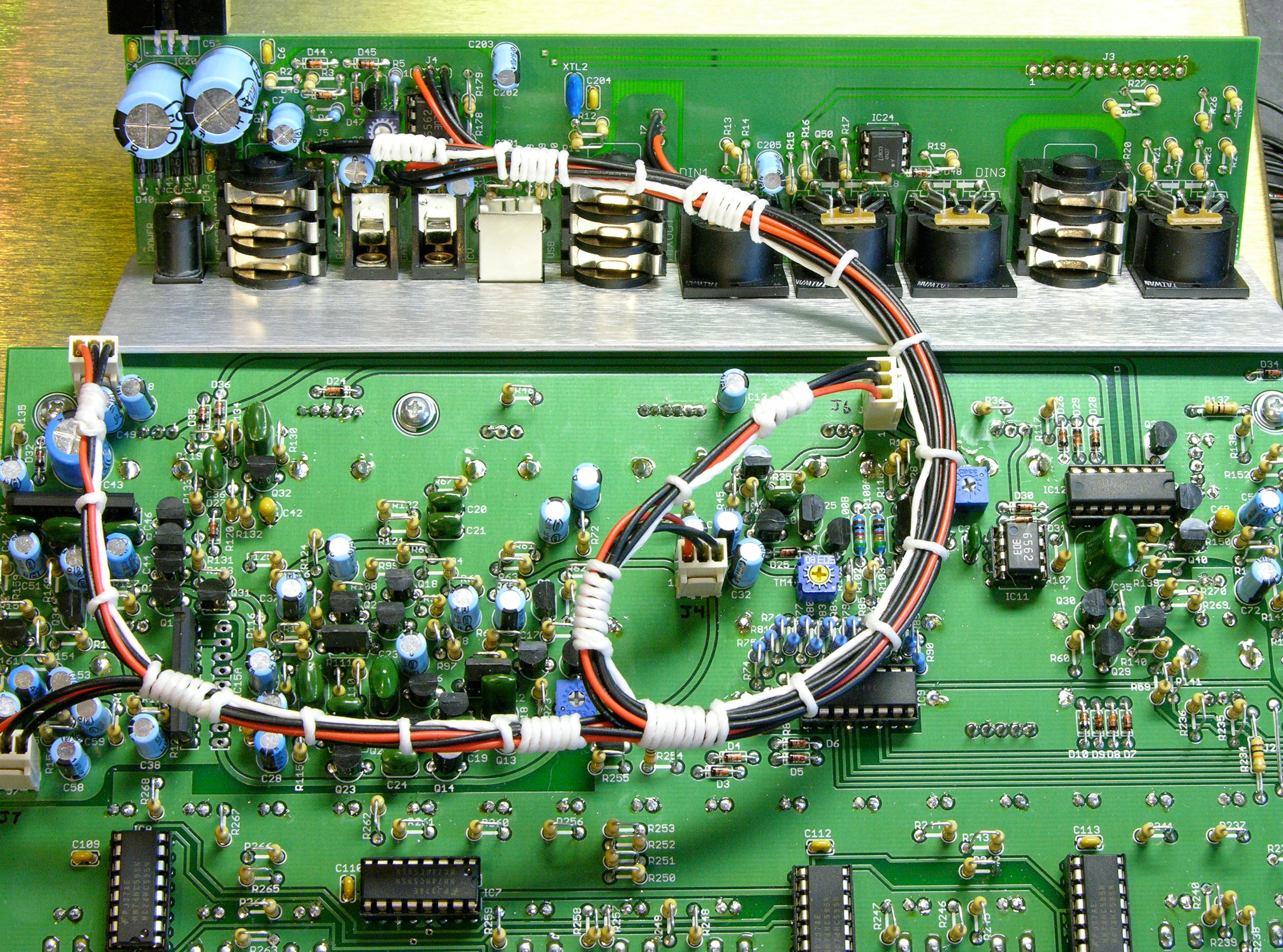
My second attempt worked much better. I brought J3′s large bundle up in a clockwise loop and all the other connectors’ bundles in an overlapping counterclockwise loop. All the cables reached where they needed to go, all the three-wire cables got tied together into a larger bundle that would hold its shape well, and the two loops flexed well to allow the back panel to be moved back and forth.
Attaching the Cables
I removed all the cables, then started with the longest run, from J7′s connector on the main board to its solder connections on the I/O board. I then used its path as a guide to size J5′s cable to length, soldered in J5′s wires, and tied the two together.
I repeated for J4 and J6, tying up after each to ensure that every successive bundle would follow its intended path and get sized correctly.
After the CCW section was finished, I soldered the J3 bundle to the right end of the I/O board and tied the two bundles together into the overlapping loop.
Since I now had everything attached, I figured I’d test the x0xb0x to make sure it worked before lacing everything into place. It was at this point that I found I couldn’t close the case because of J3′s connector being at the wrong end.
Besides having to desolder J3 at both ends and reattach it, this broke my plan to have the overlapping loops tied together. It wouldn’t do much good to have wires soldered to the I/O board tied to wires soldered to the main board. I could still leave the overlapping loops; I just couldn’t tie them together.
Lacing the Harnesses
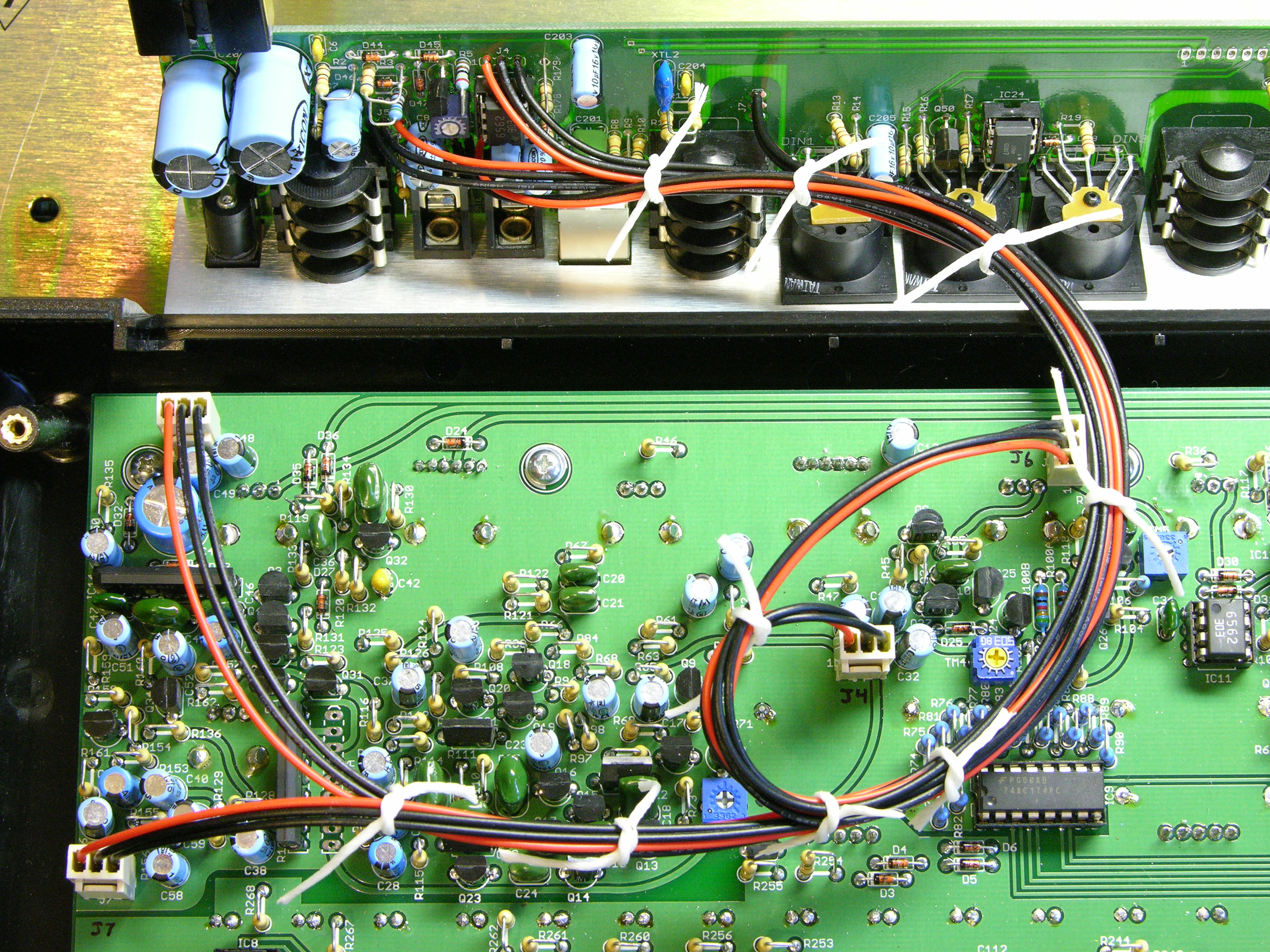
After desoldering J3 and setting it aside, I laced the harness that holds everything else. I started at the I/O board, locking and wrapping every time another cable joined or left the bundle and removing my temporary ties along the way. Because of the number of branches, the usual advice of two and a half times as much lacing cord as the length of the main trunk left me short, and I had to run the main cord up to J4-J6 and start a new cord to finish out the run to J7-J5 instead of the other way ’round.
Note that I ended up routing J7 as a short branch off the run to J5 rather than splitting the two in a Y like I mocked up.
I understand that it would be more proper also to tie every bundle of three wires after it splits off the main trunk; but with only about an inch on each after the branch, I’m satisfied with the results.
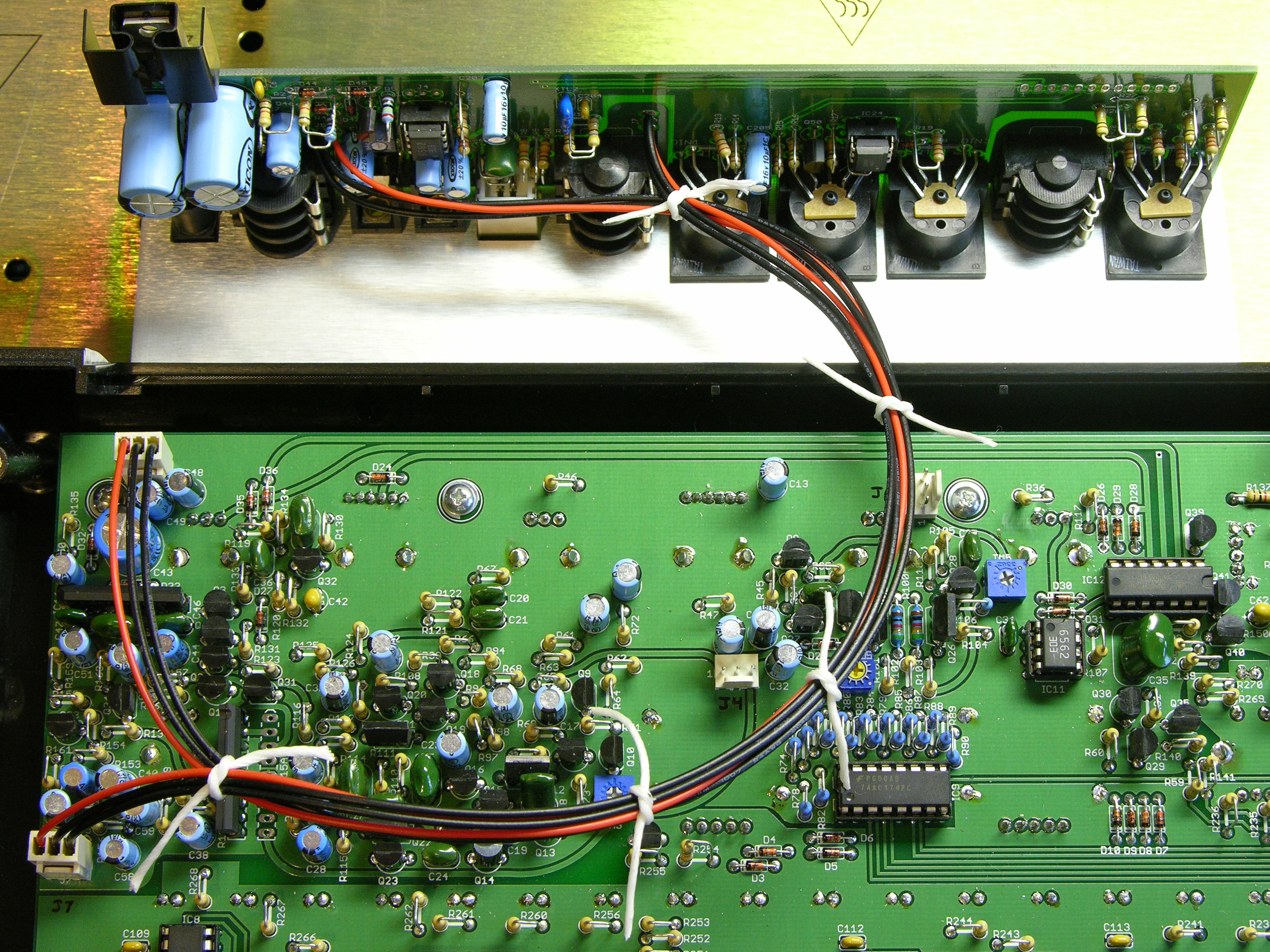
The harness holds its shape well and it’s easy to see where every three-pin connector is supposed to plug in.
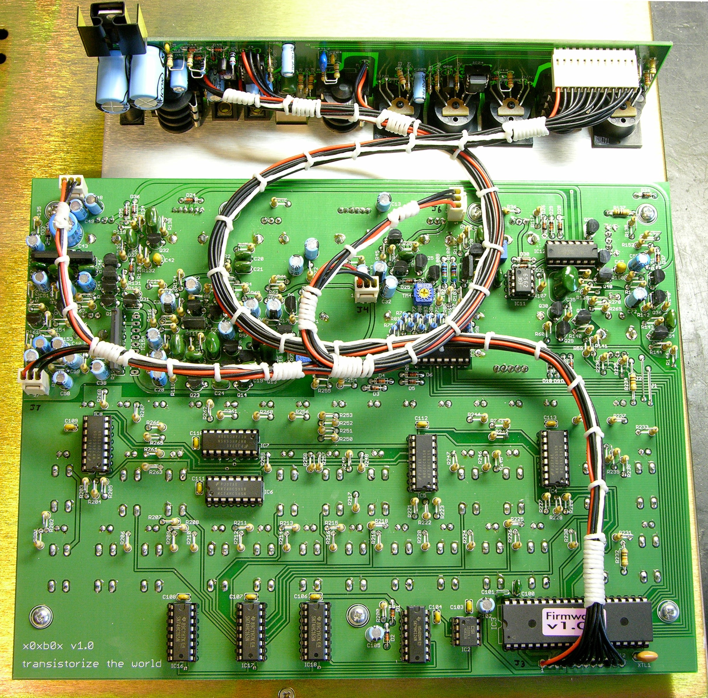
After reattaching the J3 buncle in the proper orientation, I laid out its path and made temporary ties to hold it in position, then started at the main board end and worked toward the I/O board. I finished with the wrap that holds the wires in shape as they fall to the left of the J3 connector on the I/O board.
Again, I’m pleased with how well the J3 harness holds its shape, especially as it doesn’t tie to any points along the way. The two harnesses’ loops overlap nicely in the middle — slightly differently than I had routed them here — and the back panel is very easy to put into and take out of the case.