Last weekend, Cort and I went to Pittsburg to help Slim‘s wife go through his mounds of AV gear and electronic parts. A couple of guys from the amateur radio club joined us, and we spent Friday night and most of the day Saturday identifying and sorting things.
For all that effort, we basically got the van cleaned out and the family room counter cleaned off. We could tell we’d made a dent, but there’s obviously a huge amount left to do. Nevertheless, Maeve was overjoyed at the work, and I think the most important thing we accomplished was helping her reduce how overwhelming the job seemed to be. Plus I got her DVD player, worldwide and NTSC-only VCRs, and Tivo hooked up to her TV so she can watch movies again.
As we sorted, we grouped things into six rough categories:
- things that Maeve will use herself
- expensive items that she should sell (possibly to one of us, possibly elsewhere)
- miscellany that one of us was interested in
- miscellany to take to the radio club grab pile
- stuff (mostly non-electronic) that won’t bring enough money to be worth the hassle of selling, but is still potentially useful to someone, to take to the thrift store
- trash
Each of us took home a few things, and I have others to talk about in due time; but the one that impresses me most was Slim’s prototyping station. Cort often talks about how important it was to Slim that people use things and how ready he was to give things away to people who would actually use them.
The radio guys aren’t really building things these days; Cort said that he and I are the only ones doing circuit design, with me doing the most right now. Because of that, Cort insisted that I be the one to take the station. I am very honored; and with great honor comes great responsibility.
The Station
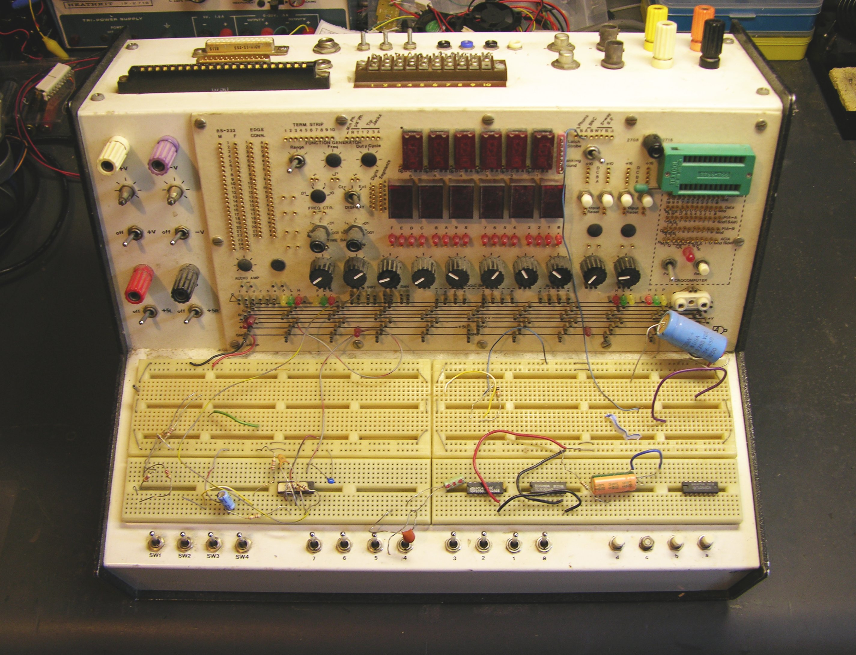
Slim designed and built this himself. To me, it not only is a very impressive piece of work, but also reflects a lifetime of experience prototyping circuits and knowing what features are useful to have at hand. A station like this should come with a manual, and it’ll take me some time to figure it out and become fluent with everything it offers.
Myriad Connnectors

Starting at the top, the station has a multitude of connectors: DB-25 male and female, a card-edge socket that reminds me of my VIC-20 days, 1/4″ and 1/8″ jacks, barrier strip, RCA, BNC, and binding posts.

Each connector breaks out to well-labelled wire sockets in an area near the left of the front panel. These pin sockets are a Slim signature item — he used them on all of his breakout and prototyping stations, and I’ve never seen them anywhere else.
Next to the connector area, in the right of the photo, is an area for a signal generator that looks like it wasn’t finished. Based on some conversations I had with Slim about signal generators, my guess is that he intended to take the board out of a commercial unit, embed it inside the case, and extend its controls to the front panel, rather than construct his own from scratch.
Power Suppply
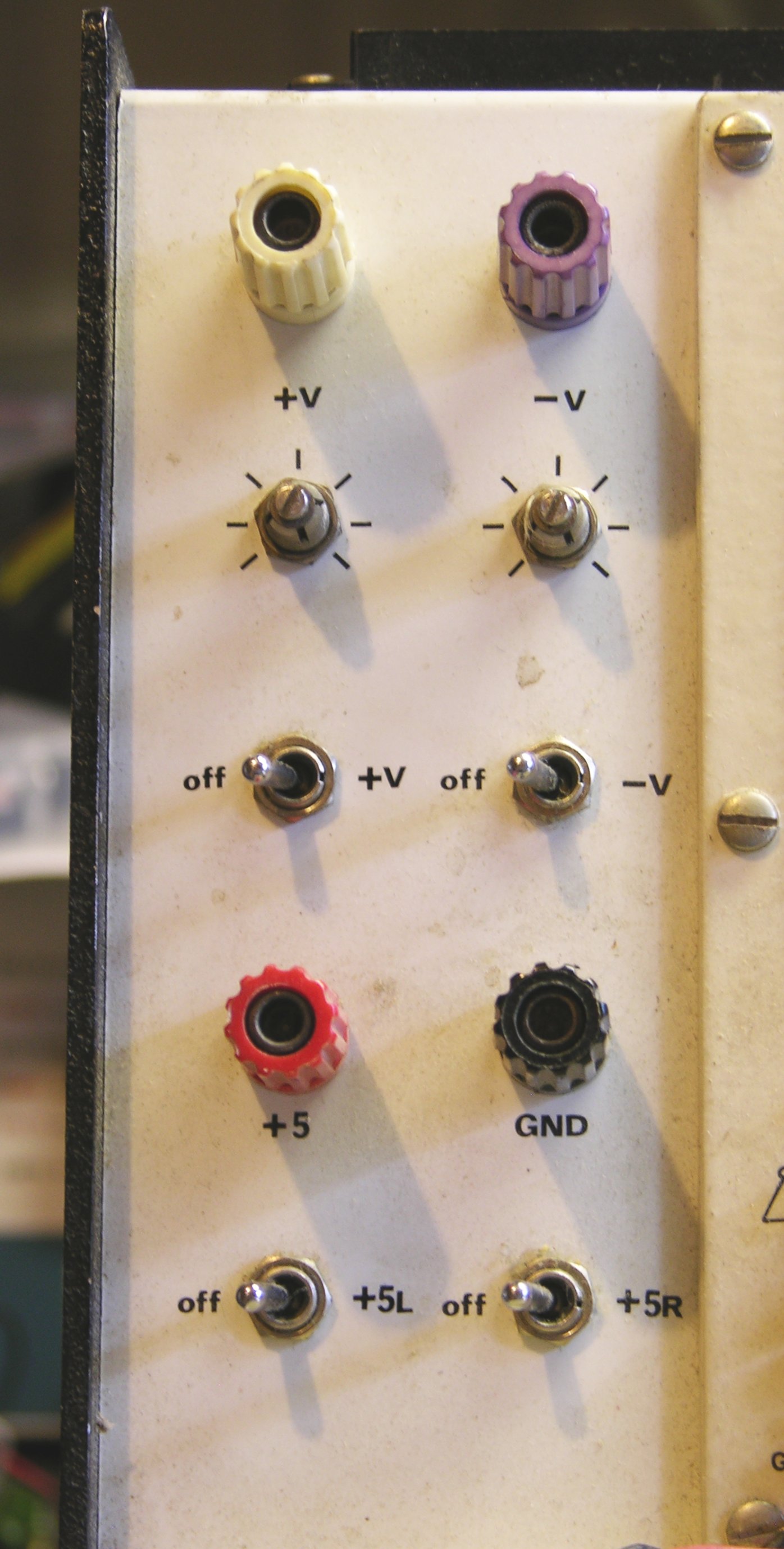
At the far left of the front panel are power supply connections providing variable + and – voltages and dual +5V supplies. If I’m following correctly, the two 5V supplies run to the ends of the rail above the breadboards, and are jumpered down to the left and right breadboard sections from there.
LEDs
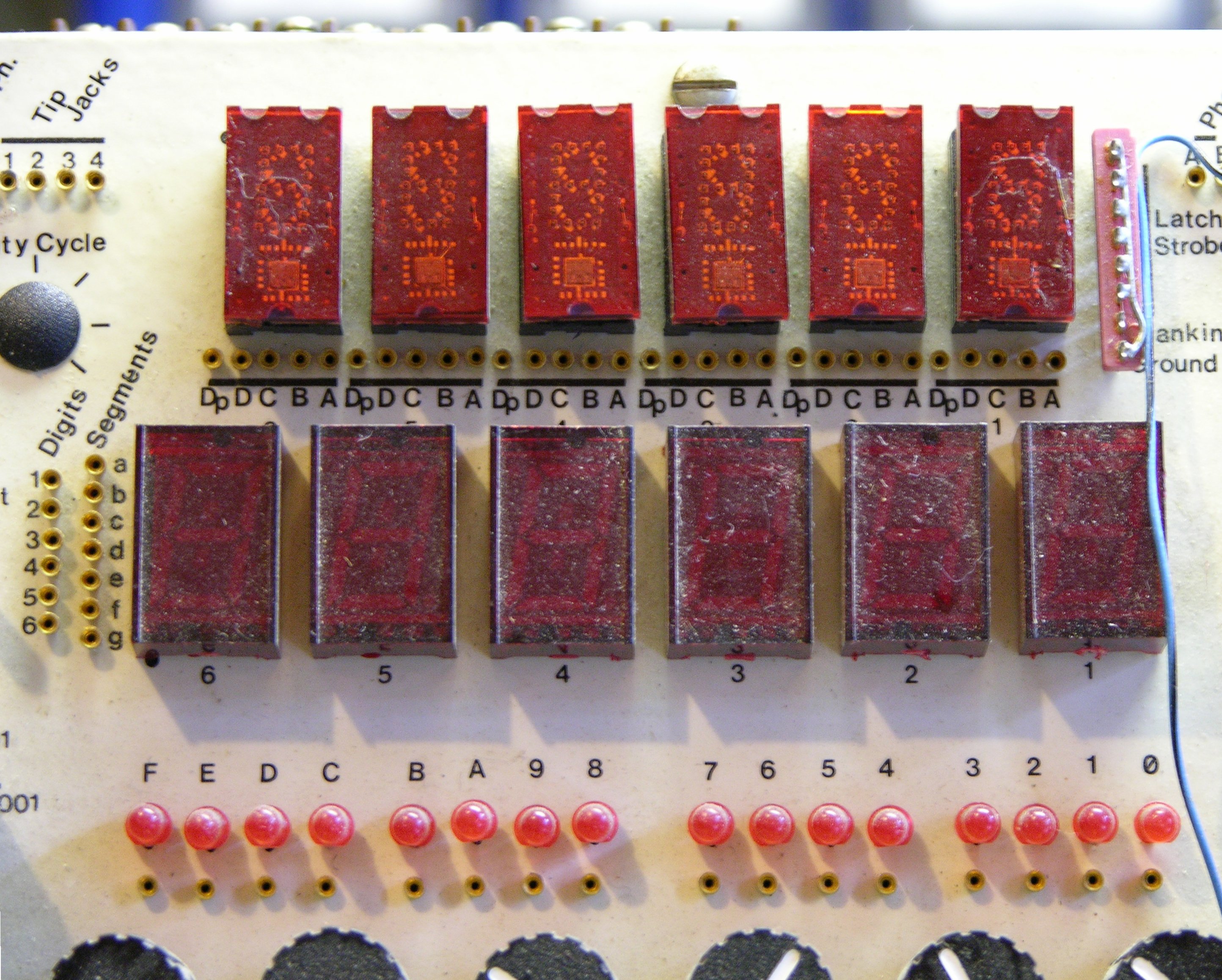
In the upper center are two six-digit sets of seven-segment LEDs. The lower set appears to be broken out for matrix drive (labelled Digits 1-6 and Segments a-g at the left), and the upper set appears to have integral decode/drive (individually labelled A-D and Dp under each digit). There’s also a set of sixteen LEDs for individual use.
Microcomputer
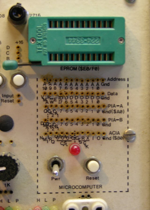
The upper right corner has a microcomputer section with a 24-pin ZIF socket for EPROMs, selectable between 2708 and 2716 (this is old school) and presumably a microprocessor hidden behind the panel. Given the PIA labels, I’d guess it’s a Z80, but it could be something else with an external PIA chip as well.
Everything Else
That’s all the closeup pictures I took, but there are a few more features I’ve already figured out. The row of black knobs across the center are potentiometers of commonly useful values, broken out to pin sockets underneath each one. The row of tracks between the pots and the breadboards delivers power and also has four buses labelled A-D.
Above the tracks are wire sockets for the switches and pushbuttons across the bottom of the case. There appear to be six logic inverters. And at each end are two sets of LEDs labelled H (red), L (green), and P (yellow) — I assume logic probes showing high, low, and pulse.
And of course a breadboard, generously sized, with a bunch of parts still on it. It has a couple of TL064s, Slim’s and Cort’s favorite op-amps, but it doesn’t look like it’s really a circuit in development. It looks more to me like it might be leftover parts that he was moving out of the way.
Using It
My challenge now is to learn to use it effectively. I always have enough clutter on my workbench that I have preferred using small breadboards and pulling out only the parts and connectors I need at the moment. On the other hand, the benefit of a prototyping station like this is always having everything at hand, saving the time of having to dig out the right connectors and displays.
It’ll definitely take some to get used to, and to determine which method really works best for me. Maybe eventually, it’ll inspire me to build my own comprehensive station that’s just right for me; and with Cort’s help, hand Slim’s station down to the next generation of experimenter.
Thanks for writing this up. My day is better just for knowing this thing exists and is in loving hands =).
John, thanks for the kind words. It’s hard to describe the respect I have for Slim, or my awestruck reaction to walking around behind the counter and seeing this beast sitting there.
And I’m not sure exactly how to say this, but it tells me something about leading a long, fulfilling life, for Slim to have had the time and desire to create something like this. I definitely think it’s worth showing to the world.
Wow!! :OO, I totally totally totally want to build one of these >:D. This is super hyper cool+awesome.
Keith,
The “gold pins” as Slim called them that you speak of are individual gold, machined pin sockets, who’s original use was for wire-wrapping. The original “gold pins” have the long square pin on the “back” side to wrap to. Several variants were harvested over the years from mil-spec equipment that didn’t have the wire-wrap back. I also use single inline header with the same pins for most of my DIP IC sockets — just trim what you need for each side an solder in. you can see them on some of the sockets from my recent repeater project.
As for the microprocessor, Slim would not have been caught using a Z80. Period. He was a die-hard Motorola man and the farthest I ever saw him stray (with the exception of the basic stamp) was a 6502, and of course. His favorites were the Motorola 6800 series. He used almost all of them, but the 6809 (before the rising popularity of the do-all microcontroller) was a favorite, and the 6805 a mainstay.
Hi Keith,
What a wonderful piece of equipment! So much thought and care has gone into it’s construction and I’m sure you’ll gain as much pleasure out of exploring it and using it as I have from simply seeing it here. Thank you for sharing!
The LED displays at the top of the 2nd last photograph might be these:
http://www.ledsales.com.au/pdf/til311.pdf
Sascha.
Hello Keith,
Came across your site from http://www.hackaday.com and enjoyed your projects and musings. Then I came to this project – stopped – and said – “WOW!”.
What are the chances that Slim had drawn up some schematics for great piece of workbench equipment? Maybe someone has come across it? If not, would be a great project to build and “re” learn electronics.
Great site!
Jim.
Jim, I’m hurt! Your favorite thing on my site is something I didn’t even do!
Naw, I’m kidding. It’s an amazing piece of work.
I doubt there are schematics for it, because Slim wouldn’t have needed to draw them out for passive components and connectors, and the more complex sections are probably complete systems that just got interfaced on the back. I can ask Cort to be sure, but I doubt we’ll find any.
That said, I’ve been thinking about the station myself. I haven’t figured out what to use as a chassis, but I’m having visions of an open-source-hardware, modular prototyping station. Something like this, but with pluggable modules (maybe 2″ square, or maybe in different sizes), where you start out with a blank station and then assemble and plug in modules that you need. Best of all, if I could get it started, anyone could contribute and/or sell modules for it.
Just a thought.
Cort says that Slim kept all of his notes, including the ones for personal projects like this, at the office, so:
man that is really cool, i came across this while trying to teach myself electronics.
i wonder what that thing looks like on the inside
maybe you can draw up some schematics…
“Somewhere, there’s a treasure trove of information on it, but I doubt we’ll ever find it.”
You know, hearing that sentence hurts. Too bad I don’t live in the area, as I would volunteer my time in finding all those little treasures. It’s those little things, the home-made schematic, hand drawings, and such that give us “electronic hobbyists” our name.
The problems with finding Slim’s stuff at the office are that
Which brings to mind a question that I think about occasionally: What provisions have you made to ensure that the things you care about end up in the hands of others who will care about them after you’re gone?
That. is. simply. gorgeous.
I am in awe. I have tears in my eyes that you were given such a treasure from a man who obviously loved what he did and did it well. Thank you for sharing this; the full image may become my next desktop wallpaper.
This is just beautiful.
I’ve been getting into electronics bit by bit over the past few years, mostly by acquiring and repairing old test year. Not only do I use the gear to learn but also to add to my workbench set up. But by far… My favorite thing are Prototyping kits.
This is just gorgeous! It’s a true work of art! Don’t get me wrong, I would be lost without my portable “KNIGHT MINILAB 2010” with all its features and wonderful portability. But this thing is just breathtaking!