I recently bought a Roland Jupiter 6 synthesizer, which debuted in 1983 and is heard in recordings of the era by artists such as Devo, Duran Duran, OMD, and Ray Parker, Jr. It’s been on my pretty-short keyboard bucket list and it was a privilege to be able to pick one up.
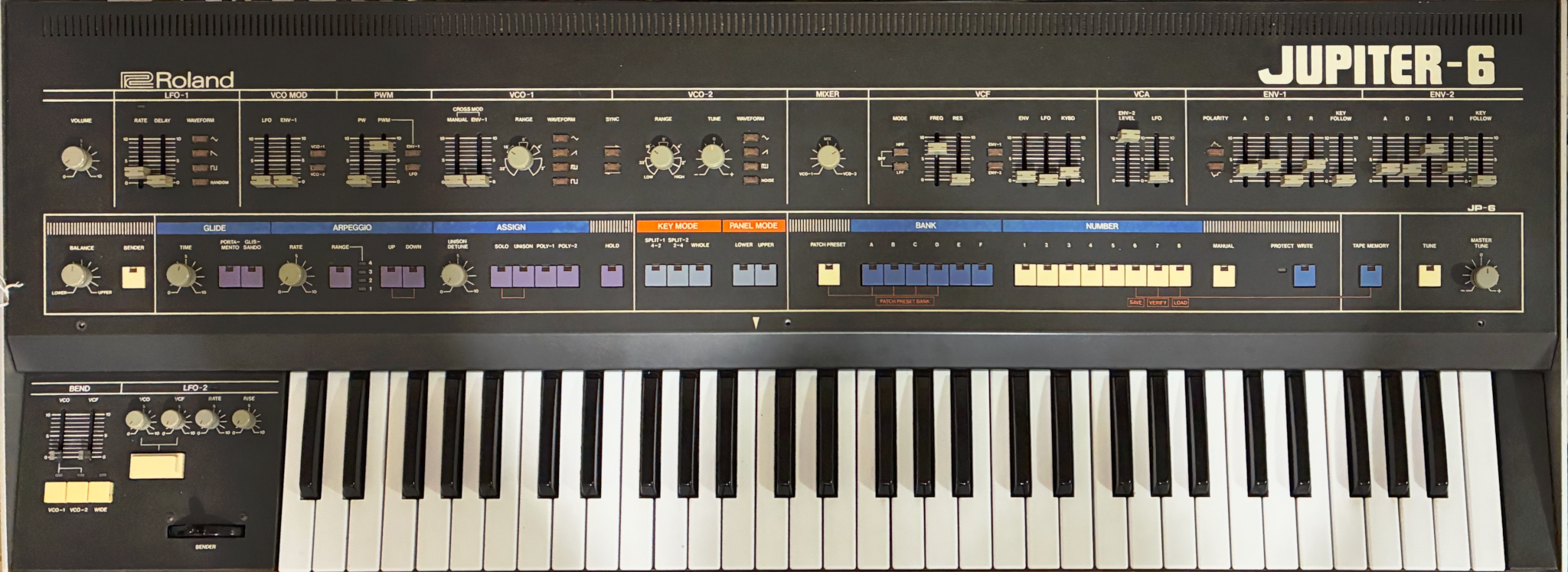
While performing a pre-sale test, the seller and I determined that something about oscillator 1 (of two) wasn’t working right on one the six voices. What follows is the process to determine which voice, determine which chip in that voice, and then replace the chip with a modern equivalent.
The Symptoms
The effect of the failed IC was that some notes didn’t sound the same as the other notes … but not always the same note. Since the JP-6 has only six “voices,” as you play keys, it dynamically maps a new voice to each new key that you play. As long as I didn’t play more than six keys, it was always the same note failing; and when I played more than six keys, it’d be a new note that didn’t sound right.
The ones that didn’t sound right had a simpler timbre than the ones that were working. Once I noticed the problem, I used the Mixer knob to listen to just the sound of Oscillator 1 on different notes, then just the sound of Oscillator 2. The problem was clearly in Oscillator 1, on just one voice. On that voice, Oscillator 1 played an octave higher than it should, and (apparently) more quietly than Osc 1 on the other voices.
Determining Which Voice
As the Jupiter 6 has six voices, a function called the Assigner maps keys (or received MIDI notes) to voices. It’s essentially NATting keys to voices. And as with actual NAT in a network device, you may or may not know the order that the mapping will be performed. I did not, nor did I find it documented.
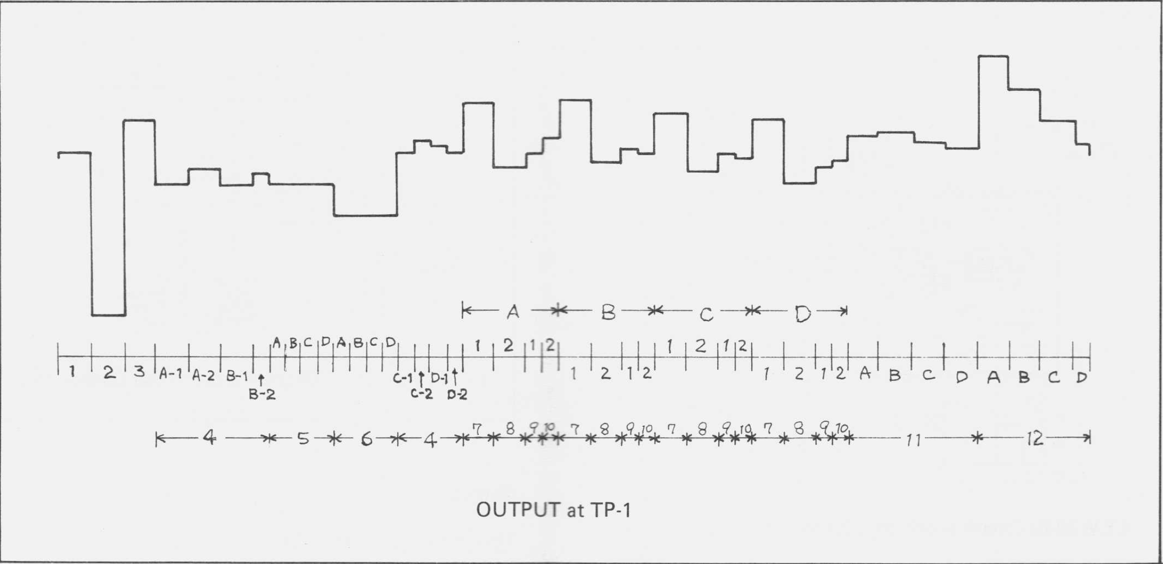
Fortunately, on p 4b, the service manual gives a sleeper of a description of an incredibly useful diagnostic feature: the JP-6 constantly samples its different internal control voltages and constructs a cityscape waverform of those sampled voltages, available on a test point on each of the two voice module boards.
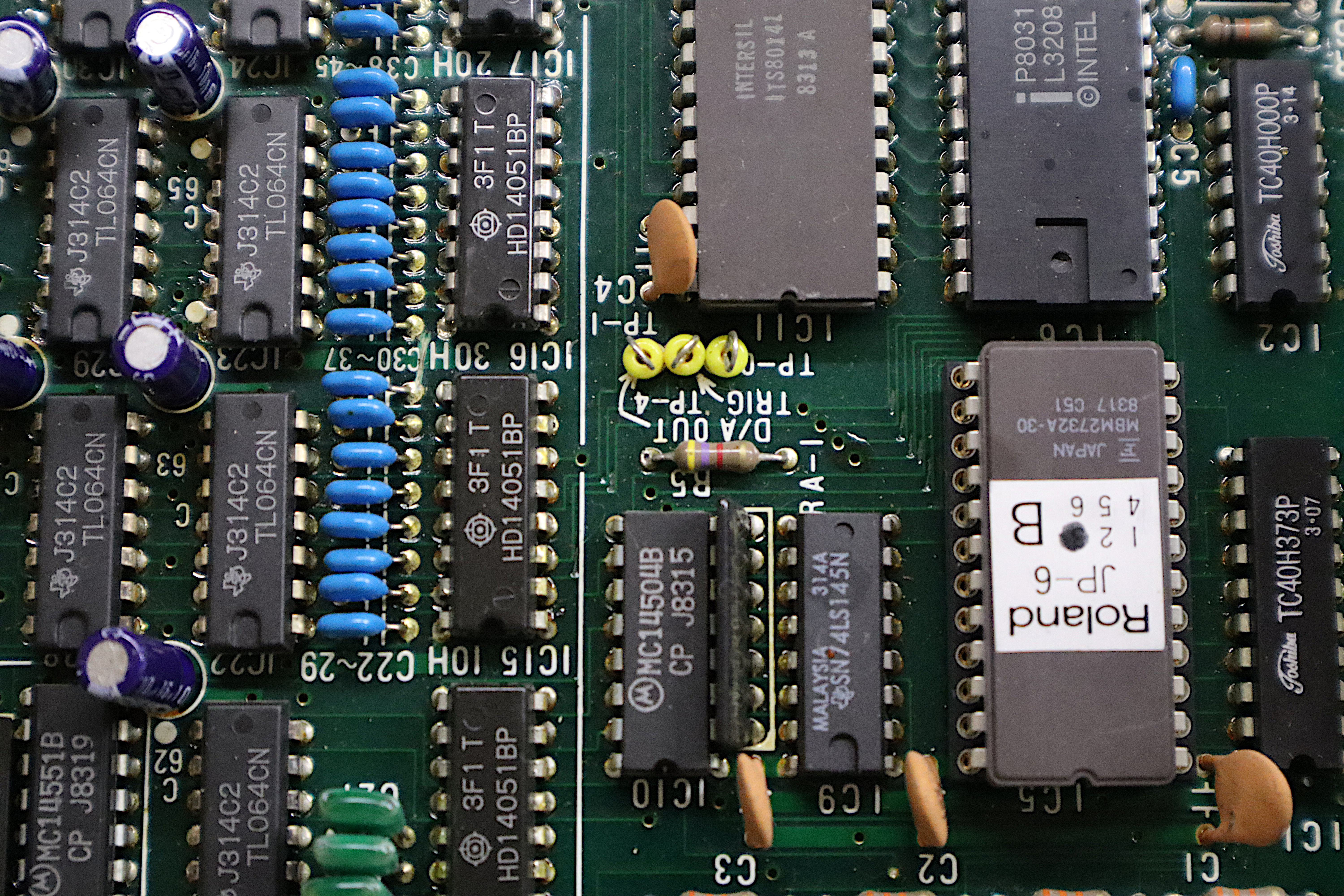
The right pin (from the perspective of the front of the synth — the boards are in the synth “upside down”) is ground; the left pin has the diagnostic waveform; and the center pin has a trigger sync that turns out to be 5V falling-edge to tell your scope when the diagnostic waveform is restarting.
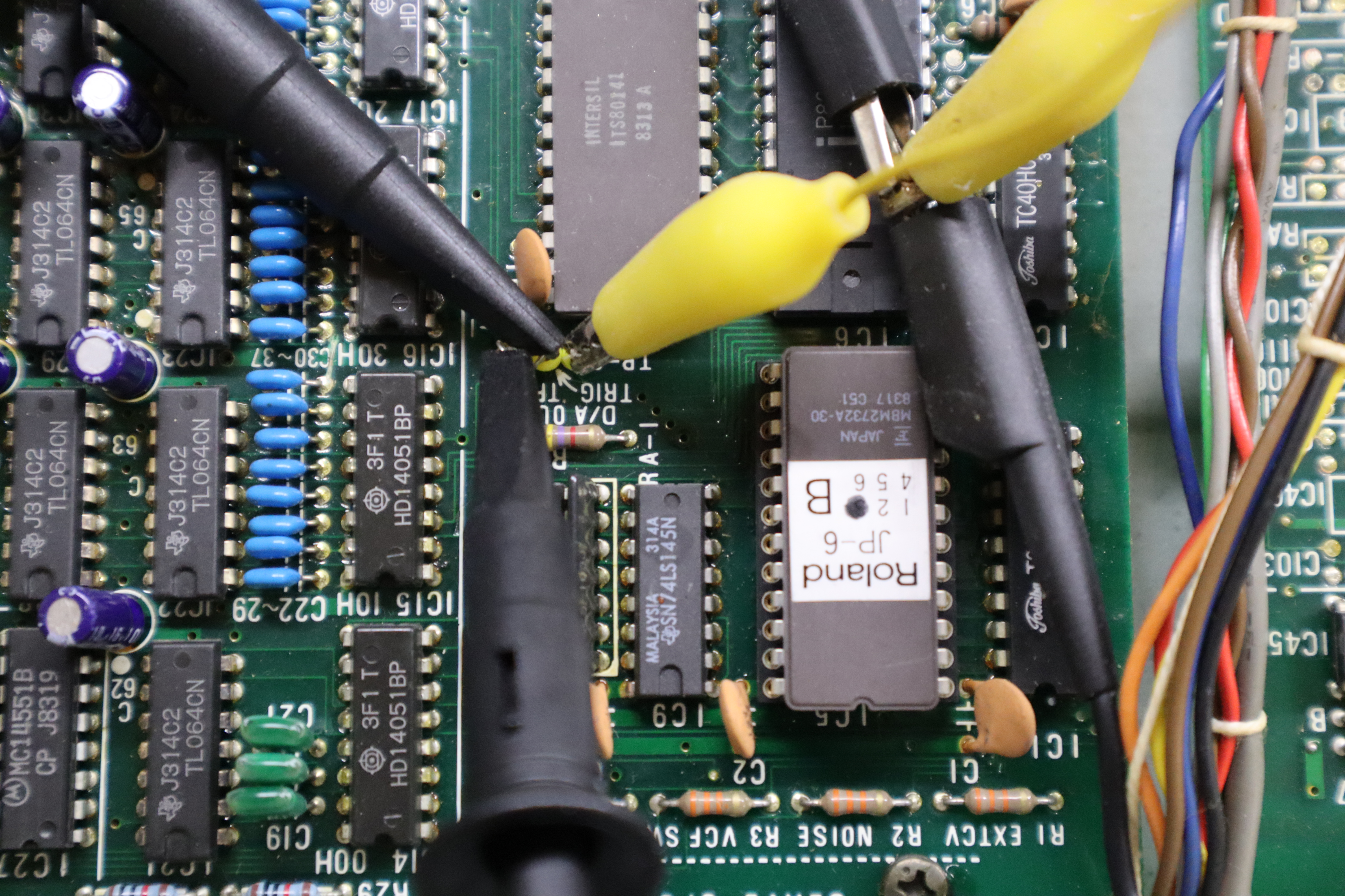
Clearly I need to build myself a hook probe with a big ring on the back to connect probe ground clips, for when I’m connecting multiple probes.
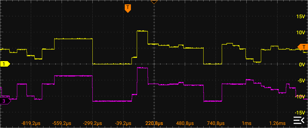
Conveniently, the CPU PCB sends its 12-MHz CPU clock to the two voice module PCBs to use on their CPUs, so the diagnostic waveform turns out to be perfectly in sync across the two voice modules and I was able to display both waveforms on my scope at the same time. I looked at the service manual’s key for the diagnostic waveform to find what signals immediately preceded the oscillator 1 control voltages and dialed those features to max to create a visual landmark.
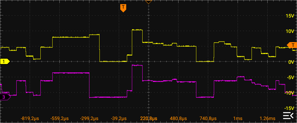
Then I played keys and watched which oscillator’s control voltage increased. Here it was four-voice board voice A (yellow) …
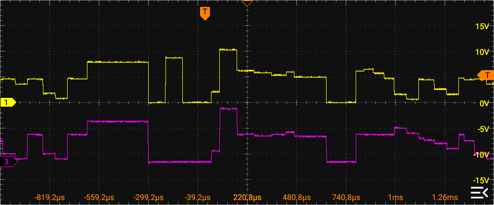
Four-voice board voice B (yellow) …
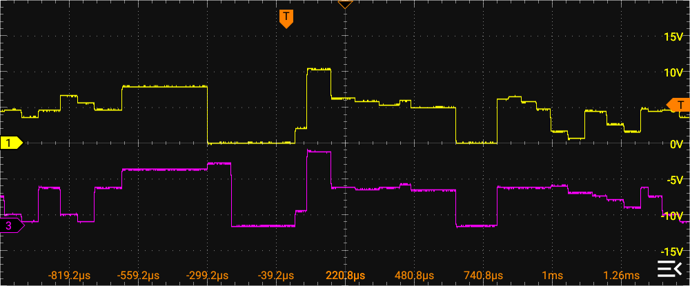
Two-voice board voice A (violet) …
These did not actually happen in a predictable order; I’ve reassembled here for easier discussion. When I played enough keys that two-voice board voice B lit up on the scope, I could hear the problem in the audio and I knew that the problem was on that voice. Further, I’d already determined it was with oscillator 1.
Determining Which Chip
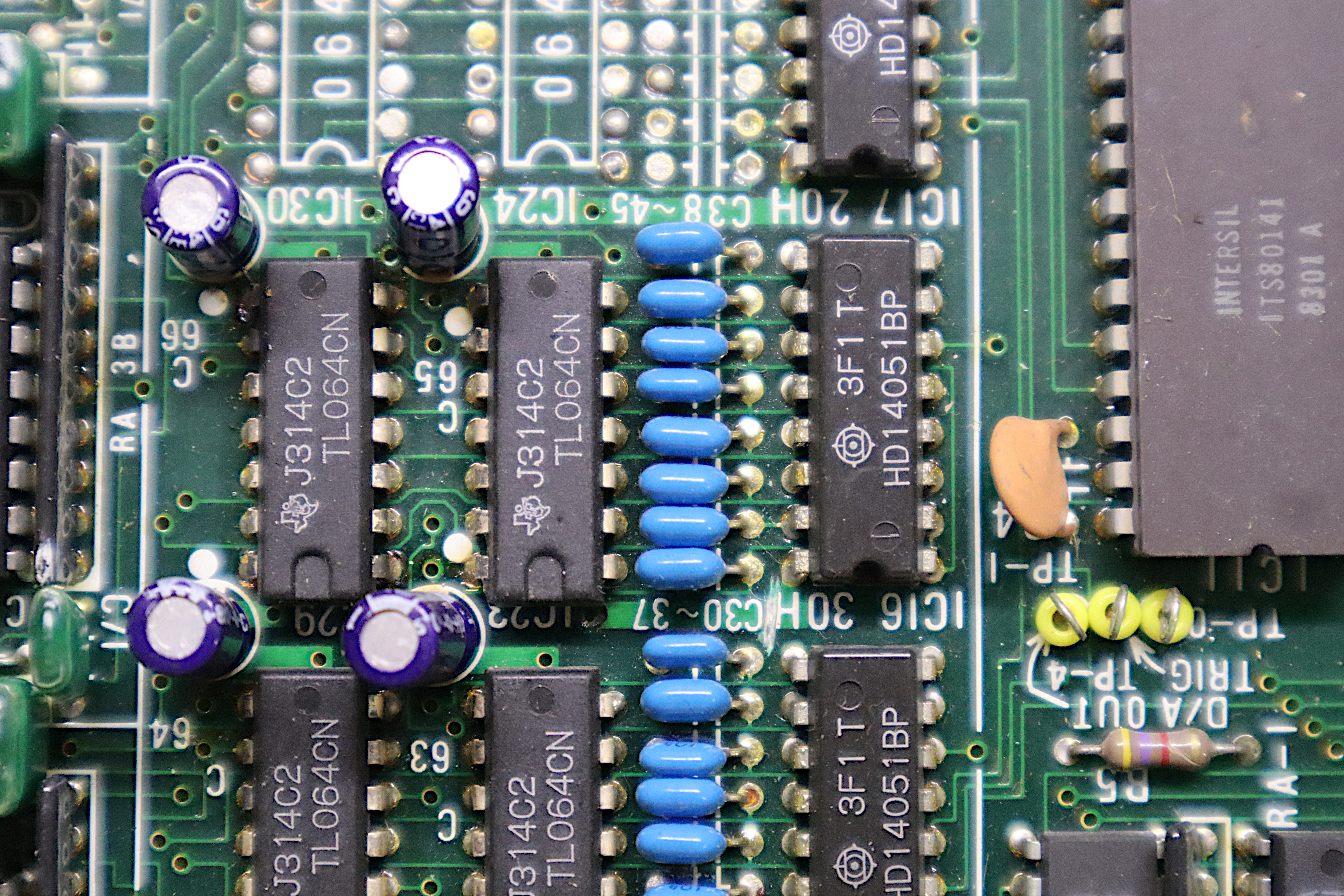
Next, I traced and checked the control voltages being fed to the oscillator IC, to make sure they were correct. The voice boards’ CPUs actually each have a single D/A converter that’s fed through a 4051 analog mux to a bank of capacitors, which hold the control voltages for different features long enough to be refreshed by the CPU coming back around to generate a new D/A for that feature; and the CVs are TL084 op-amp buffered to the different chips that use them;
so I checked the B1 CV (main pitch control — sum of pitch from octave range selector, keyboard, LFO pitch modulation, and detuning setting) and FREQ (pitch adjustment — sum of internal tuning and envelope pitch modulation) signals to make sure they were similar between the buffers feeding a working oscillator and the nonworking B1. Which they were. Similar. The problem didn’t appear to be in the control voltages.
Testing the CEM 3340 Voltage-Controlled Oscillator
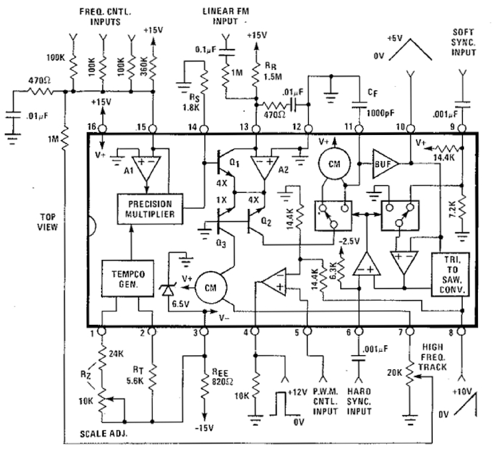
So with the problem downstream of the oscillator control voltages, I reviewed the datasheet for the Curtis CEM 3340 VCO IC used in the Jupiter 6. Interestingly, it generates three waveforms all the time; and interestingly, it generates them at different voltages. First it synthesizes a 5V triangle wave at the right pitch, then by an undisclosed method converts it to a 10V rising sawtooth, then by a comparator converts it to a 12V PWM waveform.
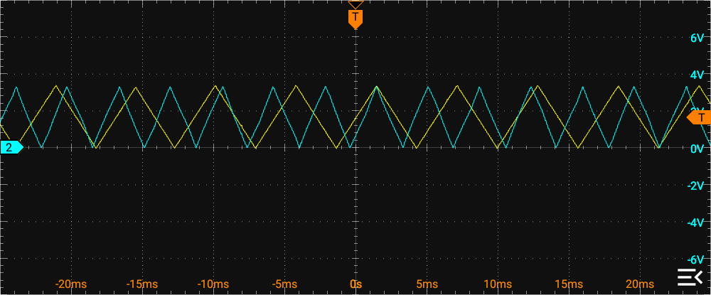
I played a six-note chromatic scale to prime all of the voice chips with as close to identical pitches as possible and put my scope on the A1 (yellow) and B1 (cyan) voices’ 3340 triangle outputs. Oh my, those pitches are not that similar.
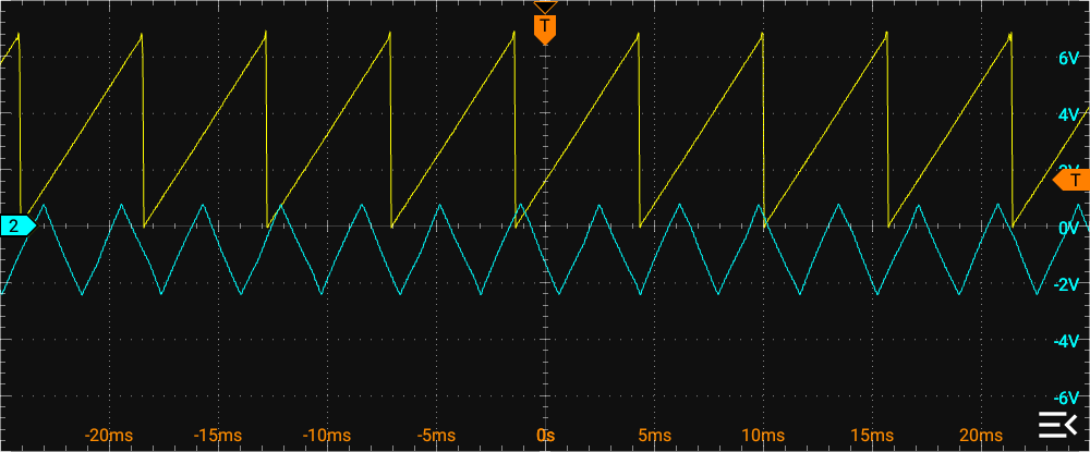
Then scoped the allegedly-sawtooth outputs. A1 has definitely converted that 5V triangle to a 10V sawtooth, but B1 sure hasn’t. The B1 3340 was definitely faulty.
Confirmation and Replacement
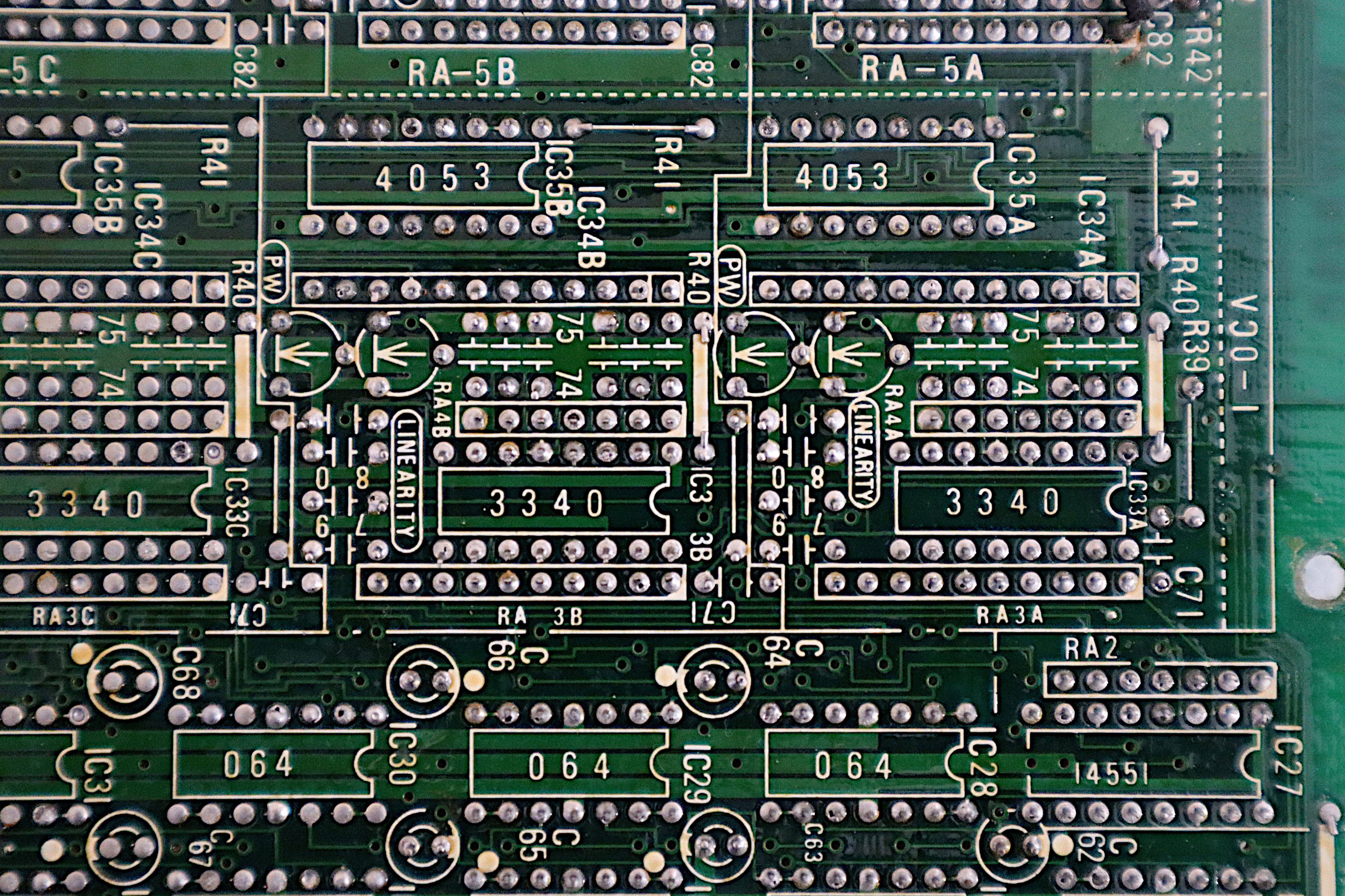
I stickered the A1 and B1 3340 chips so I wouldn’t lose track of which was which. Then I carefully desoldered them, which was a delight with the solder side of the board so clearly labeled for anticipated field service, then soldered in sockets.
I swapped the 3340s, reconnected the scope to the test points, and verified that the problem followed the original B1 chip to its temporary A1 position. Yup, that chip is bad.
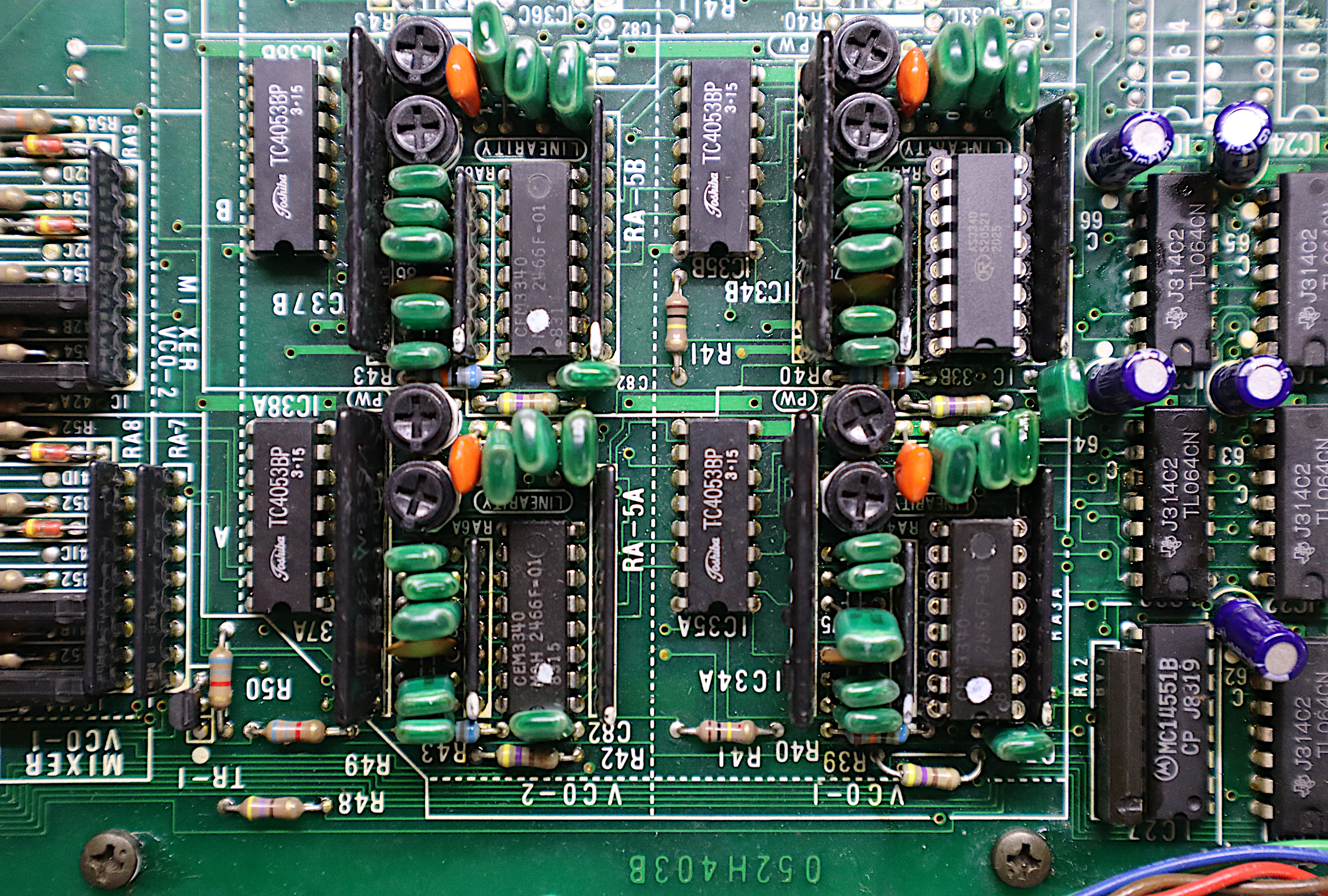
It turns out the CEM 3340 was such a popular VCO that not only has Curtis reissued the chip, but other vendors have made pin-compatible replacements with even better thermal stability. I ordered the ALFA RPAR AS3340 from synthCube, popped it in (upper right of the four 3340 chips surrounded by SIP resistor arrays) today when it arrived, and everything is now working as designed.