A few weeks ago, John mentioned to me that one of the audio mixers in the art and technology / Internet radio station lab had stopped powering on. I said I’d have a look at the power supply and see if I could fix it, and he sent it with me. Turns out we both got a little more than we bargained for — I in terms of effort required and he in terms of time without the mixer.
I didn’t know whether it’d be a linear or switching power supply, and it turned out to be switching. I figured it’d just have some baked electrolytic capacitors I could replace, and it turned out that was just the beginning.
I’ve got it mostly fixed now, and it’s been a long and interesting road.
Getting In
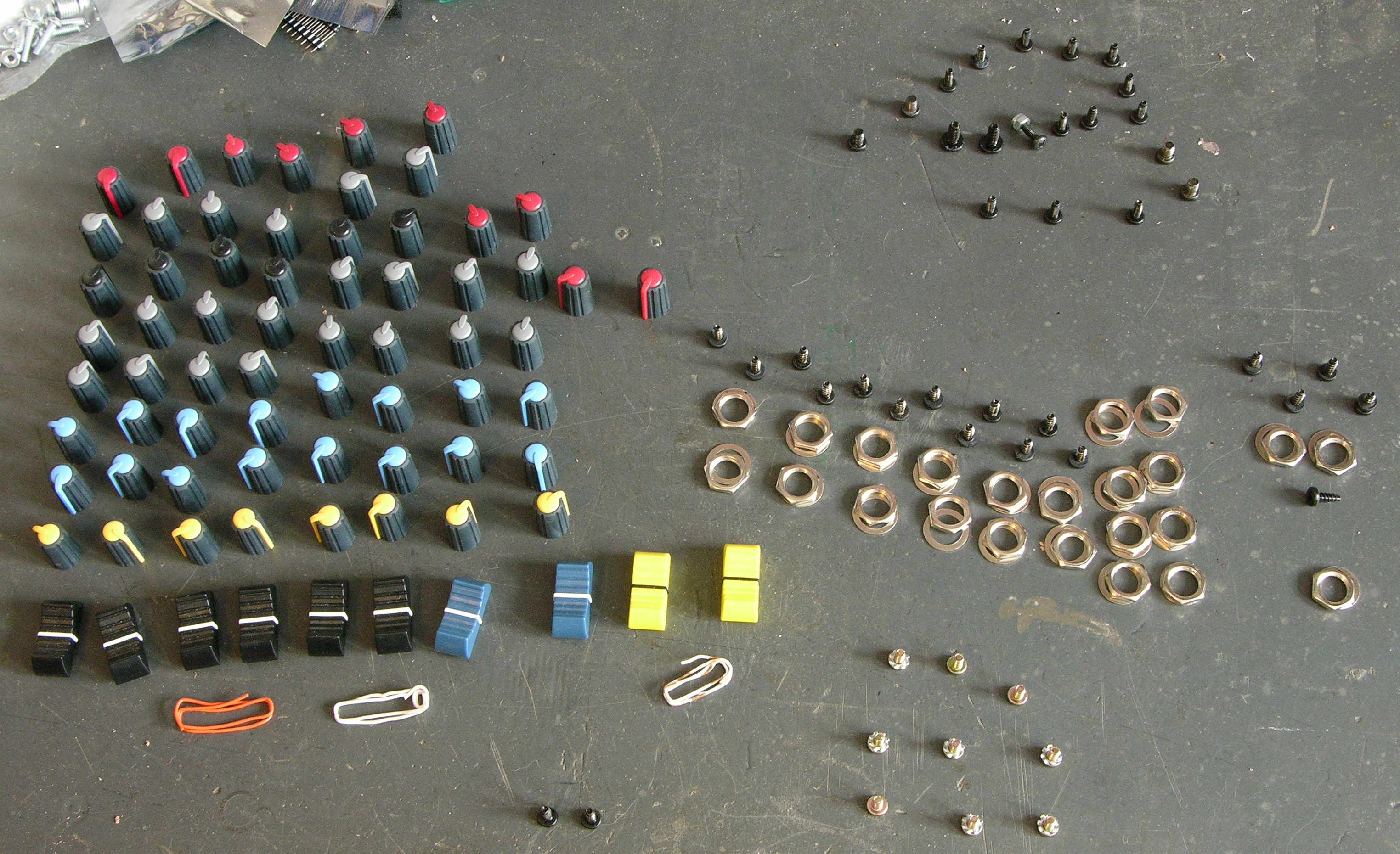
First off, you can’t get into the mixer from the back, so I had to take every knob, screw, and nut off the front panel. I’ve had this assortment on my workbench for several weeks, in the way and patiently waiting for reassembly.
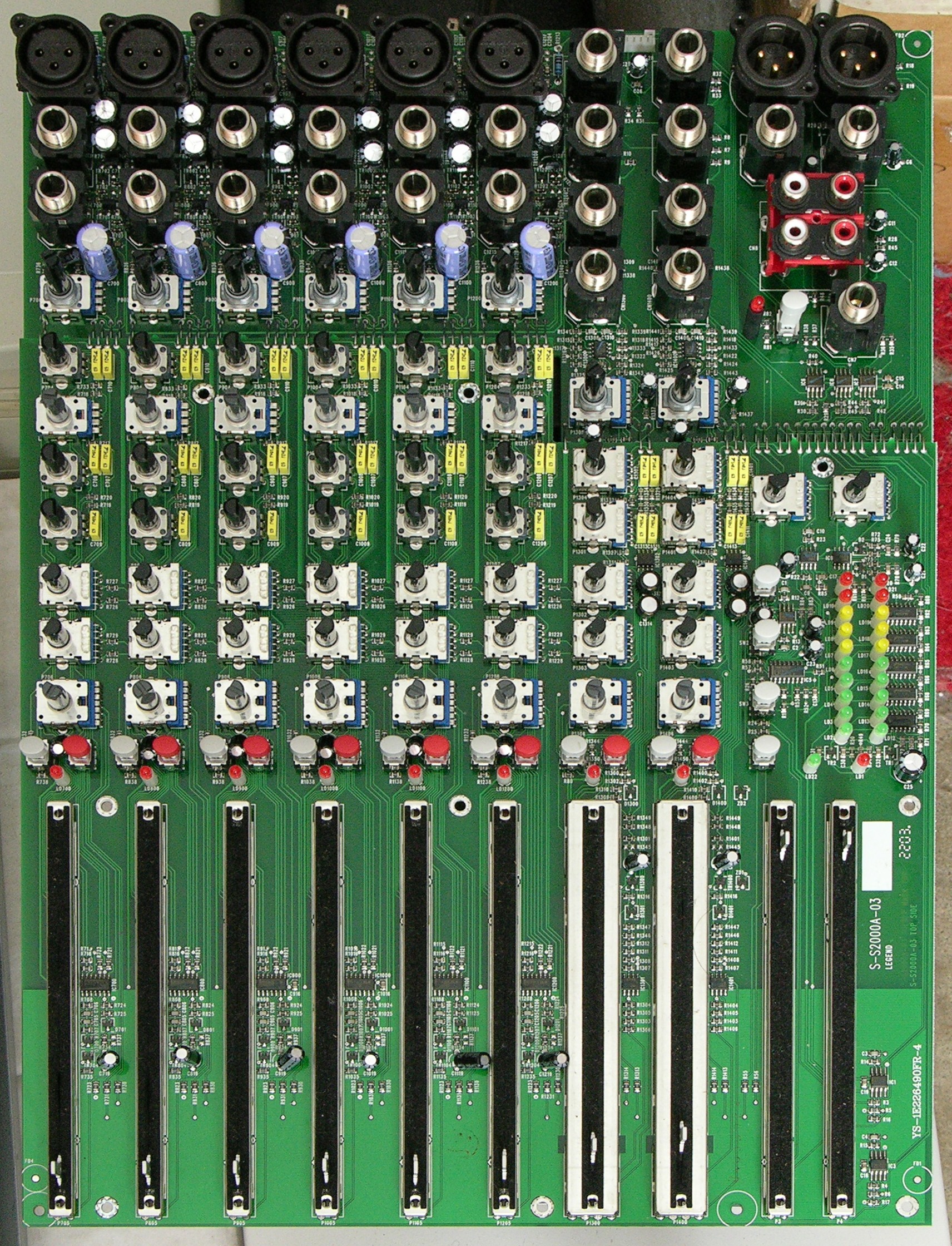
Here’s the main board. It’s so hard to see the active components, it looks almost like it’s just a control board, but that’s the whole deal — all the op-amps are tiny little SMT jobbers hiding between the jacks and faders.
Then I had to dig the power supply out of a gully in the back of the case — yet more screws to keep track of.
Capacitors
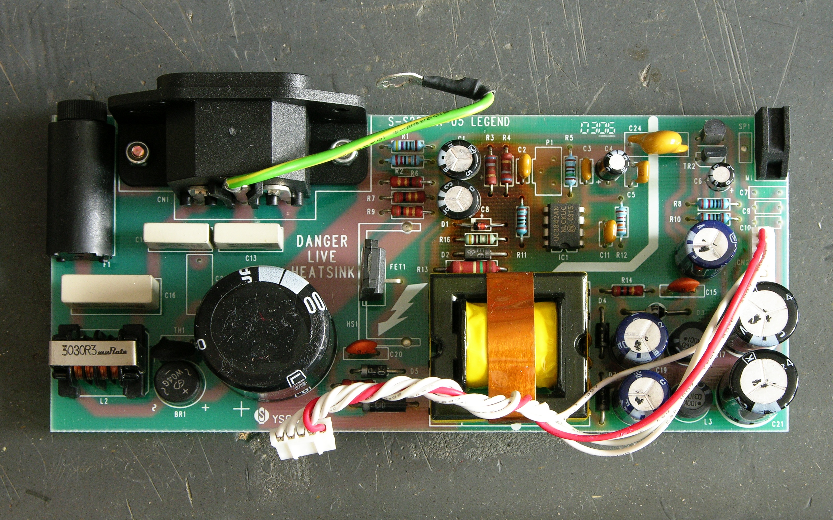
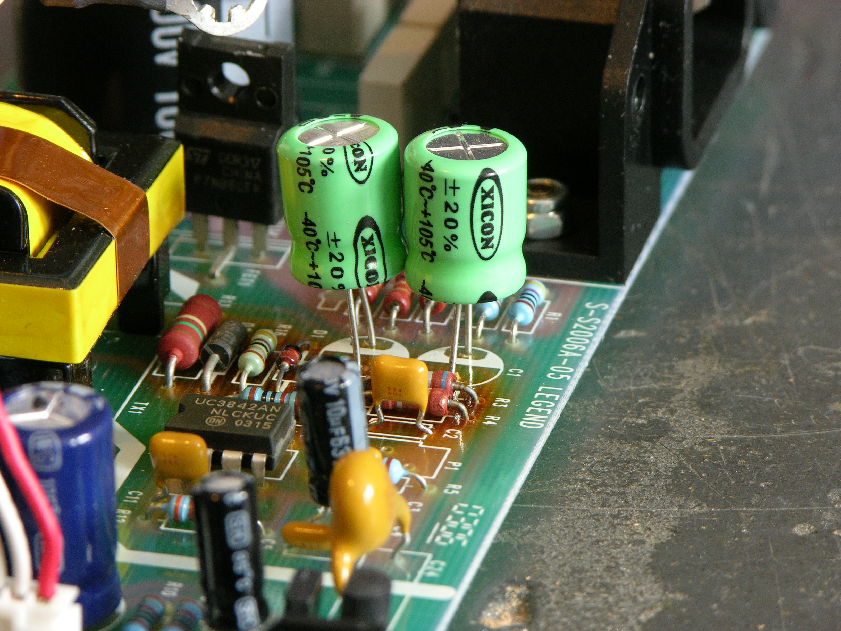
See that scorched area in the upper middle of the board? I was suspicious of the two electrolytics right next to it.
I pulled out Ye Olde Capacitor Wizard, and sure enough, C1 and C8 (47uF 63V 85°C) both tested way bad. I replaced them with 47uF 100V 105°C capacitors, raising to get them a little further away from the resistors that I assumed were the source of the heat. This is probably not kosher, but then neither is failing to take thermal considerations into account and baking the capacitors.
And voom! The power supply … er, still didn’t work. Durn.
Sam’s Switching Power Supply Repair FAQ
Since I knew nothing about switching power supplies other than vague theory — and at the time still had every desire to keep it that way — I Googled for “troubleshooting switching power supplies” and went off to read Sam Goldwasser’s excellent troubleshooting guide. It even has a section on the UC3842 control chip used in this supply.
Alas, none of the problems that “probably account for 95% or more of the common SMPS ailments” seemed to pertain. (I find that they don’t 95% of the time.) Under “Supply dead, fuse not blown,” it suggests a bad startup resistor, bad fusable resistors, and bad controller components.
Startup resistor — okay, now I was having to learn a little more about how off-line switching power supplies work.
In an off-line power supply, ac line voltage is rectified and filtered without using a line frequency isolation transformer. Great; not only is there 110-120VAC in there, and 155-170VDC, but the entire primary side is powered by directly rectified AC and is “live” with respect to earth.
I’ll say it now and I’ll say it again later — don’t poke around in a powered-up off-line power supply unless you have it plugged into an isolation transformer. You don’t want to chance touching a connection that’s hot to earth and having it short through you. You also don’t want to connect the power supply’s floating ground — which is still hot with respect to earth — to your scope’s ground; it’ll send a whole lot of electricity through things before it melts one, the other, or both. For safety’s sake, you’re best off using a battery-powered meter, which doesn’t provide any return path to earth.
Right, back to that startup resistor. In this type of supply, the primary side of the circuit is running off rectified line voltage — in this case, about 170VDC. A high-valued startup or bootstrap resistor is used to provide VCC to the control IC — in this case, as I learned shortly, by charging C1.
The UC3842 control IC is designed so that it turns on when VCC climbs to 16V, increases its current consumption so it’s now draining C1, starts driving the FET to power the transformer primary and hopefully get the supply bootstrapped, and turn off if VCC falls to 10V by depleting C1 before the main supply manages to bootstrap. This is why failed switching power supplies sometimes chirp, chirp, chirp or flash their power LED — which I found out later this one had been doing before it went completely dead.
Once the system is bootstrapped, it draws from a transformer secondary to power the control IC on the primary side.
Startup resistor — right. A bad startup resistor could make the supply never bootstrap. In retrospect, it makes sense that it’s the large resistor in the circuit, because it’ll have about 170V dropped across it, but I wasn’t thinking of that at the time. Which leads me to …
Building a Schematic
Didn’t have one. Needed one. Made one.
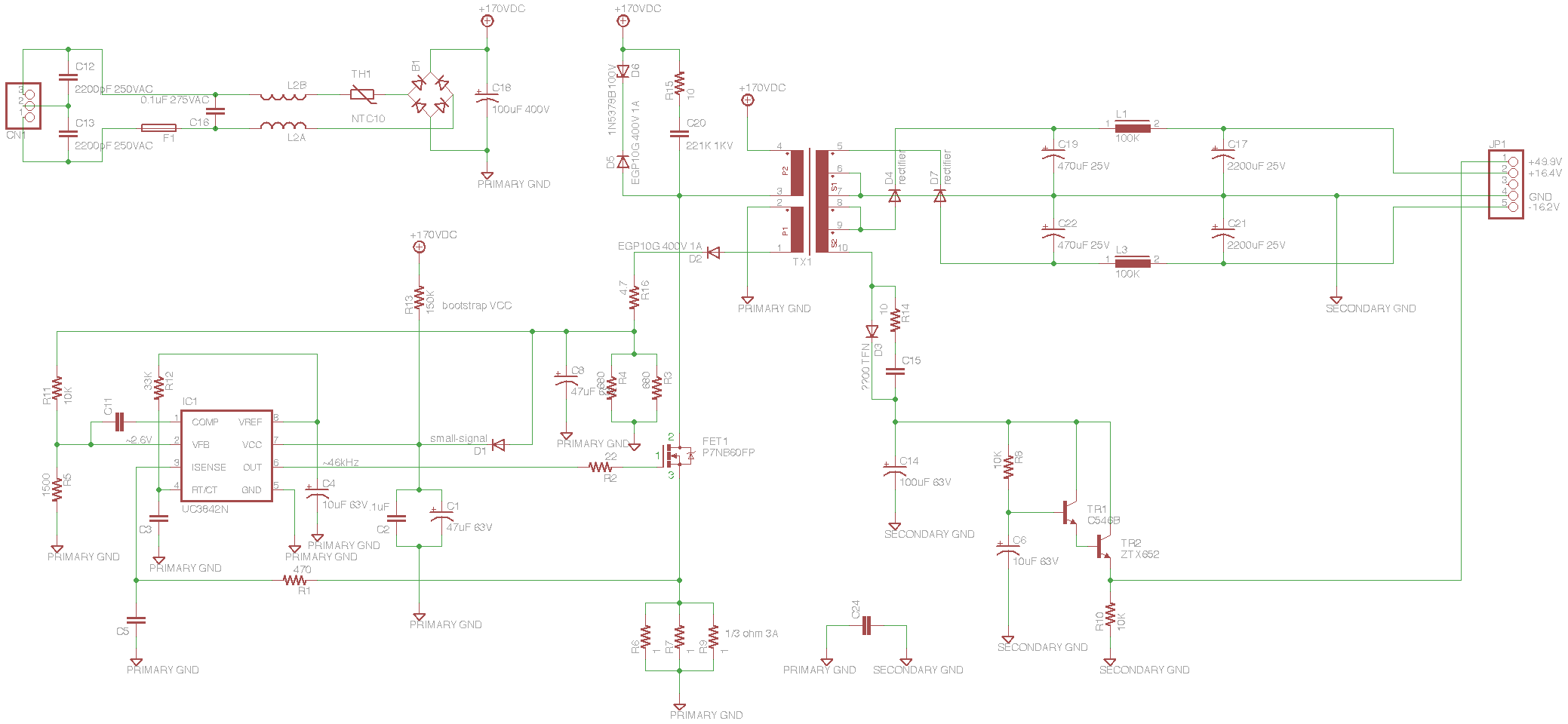
I looked at all the components on the board, placed them in EAGLE in corresponding positions, and then joined connections to follow the traces on the board. Then I rearranged the schematic by logical sections, and that’s what you see here (since annotated with voltages you should see at different points in the circuit, for the sake of the next person to repair one of these).
The whole thing makes a lot more sense now. In the upper left, the incoming AC has RF filter capacitors across it, a fuse, RF filter inductors (it physically looks like a transformer and maybe technically is but the coils are side-by-side instead of concentric and it has an air core), a thermal fuse, a surprisingly small bridge rectifier (high voltage but low current), and a big 100uF 400V capacitor.
The primary side of the circuit charges C1 through R13 to bootstrap VCC up to the 16V turn-on voltage. The UC3842 drives the FET that switches the transformer primary. A primary-side secondary is half-wave rectified to provide ongoing VCC to the IC, and the rest of the primary side is kitted out with all the various feedback the UC3842 needs to operate.
The secondary side has half-wave rectifiers with pi filters (capacitor to ground, inline inductor, capacitor to ground) to provide balanced ± power to the op-amps in the mixer. The oddball dangly thing regulates the 48V phantom microphone power.
I’ll note that brown bands on brown resistors look grey to me, leading to some intial confusion as to resistor values.
Testing Begins in Earnest: Bootstrap Resistor
With the schematic in hand, I could now make a logical progression through the circuit, testing components in turn, to locate the remaining problem(s). My plan was to test the power to the IC, the FET drive signal, then the transformer primary power, to isolate the problem to the appropriate section of the circuit, and narrow down from there.
First I tested the bootstrap resistor, R13. Looked good — and I desoldered and lifted one lead to be sure I wasn’t being misled by some parallel part of the circuit. Seemed okay.
I wanted to check the actual bootstrap VCC voltage, because I was suspicous that it might be too low to turn on the chip. To do this, I needed to power up the circuit, so I did two things: I plugged the power supply into my isolation transformer so if I accidentally touched part of the circuit I didn’t intend to, I’d just be hurt instead of (potentially) dead; and I plugged the mixer’s main board into the power supply on my bench, to provide a load.
Switching power supplies that have feedback from the secondary voltage to the control IC are particular about having a load. Although this supply does all of its regulation within the primary side, changing the load will change the current draw of the transformer secondary which changes the current draw of the primary which changes how the circuit behaves. It might be okay to run this supply without a load; but frankly I just don’t know enough and didn’t want to chance it.
Powered from the isolation transformer, with the main board plugged in for load, and using my battery-powered meter (not essential since the supply was on isolation, but the handheld meter was the first piece of equipment I wanted to use anyway), I measured a fluctuating 12-14VDC on the VCC line.
This told me that the system wasn’t bootstrapping, as it should have a steady supply voltage once running — but of course I already knew that. What it didn’t tell me was whether I had a bootstrap voltage problem. I was using my digital meter, which doesn’t have a fast enough response to be sure about the exact extremes of a fluctuating DC signal.
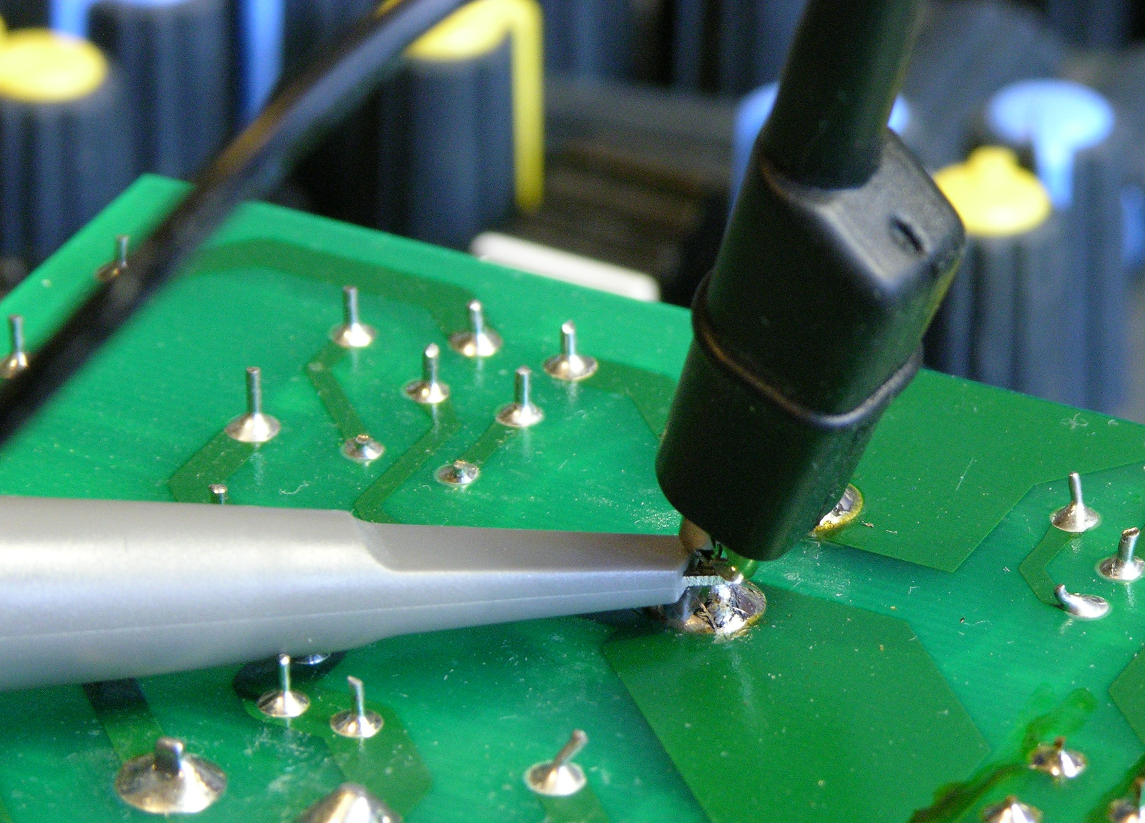
I figured I was going to be spending a fair bit of time testing things on the supply, so I soldered a wire to the primary side’s big capacitor’s negative terminal to use as a ground point to clip my scope’s ground lead to — I didn’t want to try to clip it to a short component lead and have it pop off and touch something else while I was testing.
Scope said 16V falling to 10V on each cycle. Aight, not a bootstrap resistor problem.
Testing the FET
Next I put the scope on the FET’s gate — lack of drive signal there would indicate that the control IC was hosed. I did have drive there:

It shouldn’t be ramping down like that, but that’s just a consequence of the bootstrap VCC draining away C1 as the supply fails to boot.
The next logical point to check was the junction between the FET drain (top) and the transformer primary, but I was still being chicken about hitting that 170V with the scope. Instead, I looked at the cathode of D2, the half-wave rectifier for the primary-side’s transformer secondary that’s the first step in providing ongoing VCC for the control IC.

It’s being filtered by C8, hence the smooth curve — but look at the amplitude. The transformer is providing only ~3VDC to the circuit; that can’t be right.
Now, I didn’t think the transformer was bad, but shorted coils in the primary side’s secondary would result in a lower voltage there and could have this effect. So I measured the ultimate DC output of the secondary side of the circuit — the voltage that was supposed to be going to power the op-amps — and saw it fluctuating from about .5 – .9V. It seems beyond comprehension that all of the transformer’s secondary taps should have shorted coils all at the same time, so I ruled out a transformer problem.
It’s worth noting that I didn’t need to consider a problem on the transformer primary — at least, not any sort of problem I’m familiar with. The two transformer failure modes I’m aware of are an open circuit and shorted coils. An open circuit in the primary side just makes it not conduct and nothing happens at all. Shorted coils decrease the primary inductance and increase the ratio of primary:secondary turns, increasing the secondary voltage (often catastrophically).
Since I had a decreased secondary voltage all around, I assumed there was nothing wrong with the transformer, but rather that there was something wrong with the power going into it.
Back to the FET, then. I still wasn’t ready to poke at the 170V, so I scoped the signal on the FET’s source (bottom), at the junction between it and the current-sense resistors.

Looked basically fine. That is, it was varying between 0V when the FET was not conducting and a higher value when it was conducting. If the FET were broken in a simple way, it would be never conducting (or always shorted), and I wouldn’t see the set of pulses as it pulled up the voltage on the sense resistors.
Fine, fine, FINE. I’ll check the dang high-voltage side.
I did switch the scope probe and the scope to 10x first.

The FET drain looked fine too — 170V most of the time, dropping to about 0V when the FET was conducting.
And I wasn’t dead. Or even injured.
Wait — What Next???
Not a bad bootstrap. Not obviously a bad control IC. Not obviously a bad FET. Not apparently a bad transformer. What the heck???
I spent more time pulling components out of circuit and testing them. C2, the small capacitor that parallels C1 on VCC to catch spikes — tested fine out of circuit. R6, R7, and R9, the current-sense resistors — really 1Ω. D2, the half-wave rectifier for the primary-side low-voltage supply — tested fine out of circuit. R5, part of the voltage divider for the voltage regulation feedback — good. What, what, what.
Bad Zener
Everything on the control side appeared to be operating properly, but the transformer’s secondary voltages were far too low. It really seemed it had to be a problem with the transformer drive circuit, and I wondered whether the FET was weak in a way I was having trouble seeing on the scope — not conducting the full current through, or something.
I found in my parts bin a similar FET also made for ultra-fast switching in power supply applications, albeit at a slightly lower current rating, and swapped it into the circuit. No discernable change. Swapped it back out.

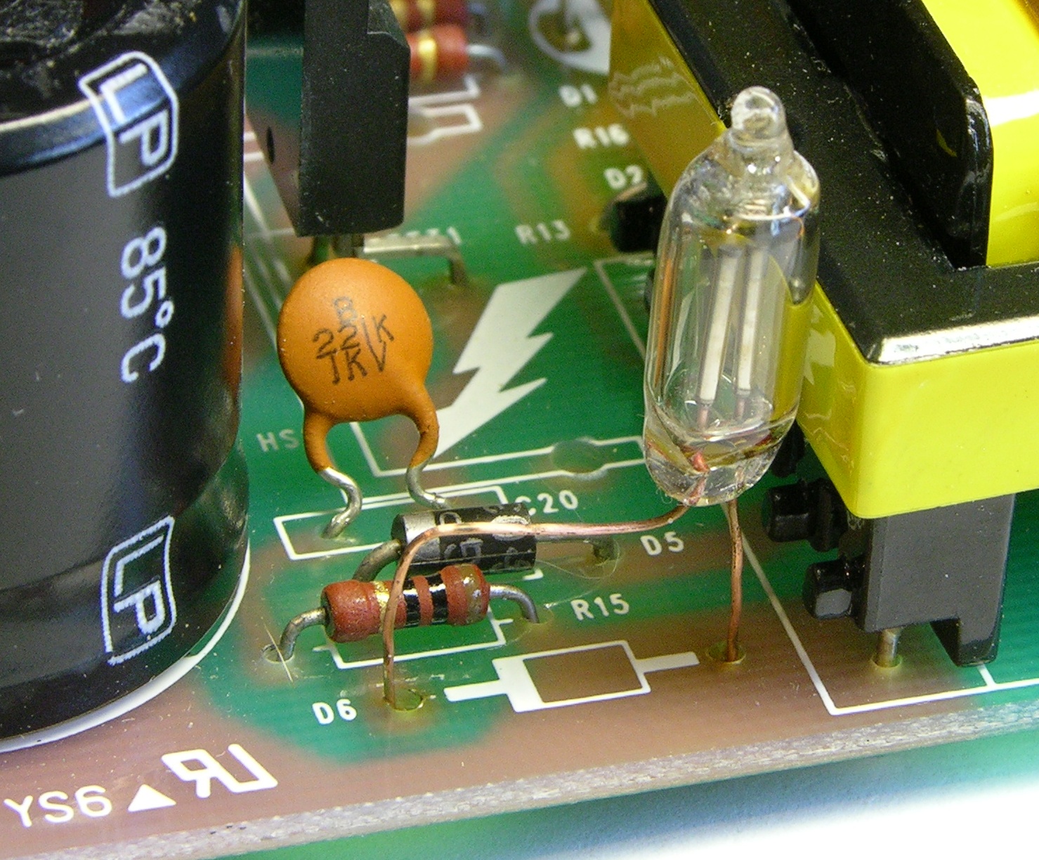
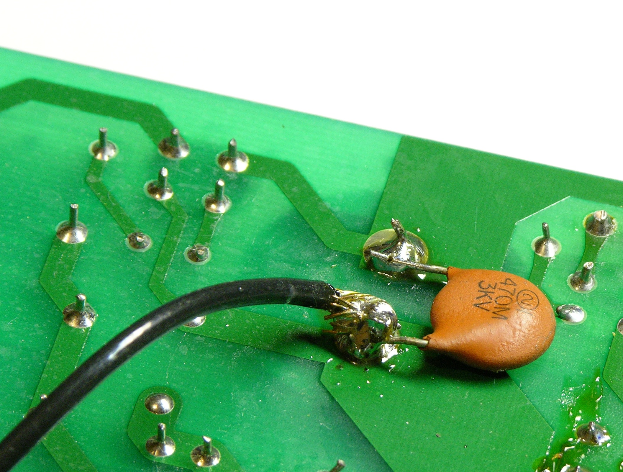
Then I looked up to the network above the FET on the transformer primary — the catch circuit for the inductive kickback. In simple terms, when you’ve been running current through an inductor and you switch off the current source, the inductor wants to keep the current flowing and causes a voltage spike in the opposite direction of your power supply. Placing a reverse-biased diode across the inductor will have no effect during normal operation, but allows the “wrong-way” voltage to be dissipated during the spike, saving wear on the other components.
D5 is that reverse-biased diode, and I hadn’t been able to read a part number on D6 while it was in-circuit (the number was facing down) but knew it must be a Zener — a diode used in reverse, which only conducts (in reverse) when the voltage across it exceeds a certain amount, called the Zener voltage. In simple terms, it clips the (reversed) voltage across it to its rated Zener voltage; or put another way, it doesn’t conduct (in reverse) unless the (reverse) voltage across it is more than the Zener voltage.
So this is a Zener diode, which is used in reverse, applied in the inductive kickback circuit, where diodes are used “backwards,” with the two reverses making it look like it’s used forward — which is why I assumed it must be a Zener. Its purpose must be to shunt the inductive kickback only when it exceeds a certain threshold above the supply voltage, instead of all the time.
I appear to have misinterpreted the function of C20 in this next section. See the comment from MikeS.
C20 is not something I usually see in kickback circuits — the only thing a capacitor can be doing there is catching some of the kickback and adding it to the next forward-going pulse. Oh, very clever! Instead of wasting the kickback by dissipating it all into the power supply, C20 recycles it, increasing efficiency.
And D6 sets the maximum voltage that C20 can catch, discarding the rest. With a traditional reverse-biased diode there, all the kickback would just dissipate through the diode and C20 wouldn’t get to keep any.
I was now wondering whether something was wrong with this catch circuit. It seemed much more likely that one of the diodes would have failed than the capacitor or resistor, so I started with the diodes.
When I measured D6 in circuit, it looked like it was conducting both directions. Oh, I thought, that’s because of other components in the circuit, so I pulled it out and measured it again. Still conducting both directions, a lot. Eureka! There’s the problem — it was dissipating all the kickback through D5, with D6 acting like a dead short, and C20 wasn’t getting to keep any, and C20 was critical to powering the transformer!
Now out of circuit and completely legible, I could see that D6 was a 1N5378B 100V Zener. I couldn’t find anything in my parts bin close to an acceptable substitute, and I didn’t want to place a parts order until I was sure that was the last thing wrong with the supply and I didn’t need to buy anything else, so I really wanted to find a substitute and check. And I had a feeling there was something else I could use, but I couldn’t think of what it was.
Faux 100V Zener
The next day I talked to Tom McGuire and John, asking if they had any 100V Zeners at work and whether they could think of anything else I could use.
They didn’t have any Zeners big enough. Tom seconded my suspicion that I could probably run it without the Zener long enough to test, letting all of the kickback go into C20 instead of shunting some; but I didn’t want to take a chance of breaking something else in the circuit at this point, so I was leery of trying that.
And then Tom reminded me of what I couldn’t think of — a neon bulb.
A small neon lamp will start conducting when its voltage exceeds about 100V (perfect!) and keep conducting until the voltage drops below maybe 60-70V (unimportant for this application). They have a long history of being used as voltage regulators in addition to indicators.
With the shorted Zener out of the circuit and the neon bulb in, the power supply worked and the mixer powered up! I couldn’t ever see the bulb light so it’s possible the kickback was never exceeding 100V, or never for long enough to light up the bulb, but I felt better having it there.
I poked around the rest of the circuit and everything else looked okay. I placed my Digi-Key order for some other stuff that had been accumulating on my shopping list, got the order yesterday, replaced the Zener, and now the mixer is tip-top!
Well, actually no.
10MHz Ringing
I was going through taking measurements of correct, baseline voltages and frequencies to add to the schematic for posterity, and I noticed that the VCC line looked awfully noisy. I zoomed in on it and found massive ringing, with the leading spikes happening at a period that appeared to correspond with the FET switching frequency and the individual oscillations in each ring at about 10MHz. I rechecked all the capacitors, replaced some anyway, supplemented some, and absolutely couldn’t get the ringing to go away.
Now, 10MHz is way above audible frequency (except perhaps for golden-eared audiophiles ![]() ), so I wasn’t worried about hearing it. Plus it was only on the primary side of the circuit, so I was pretty sure it couldn’t couple through the transformer to the secondary. But I didn’t figure it was great for the control IC to have that on its supply, and I was worried about it shortening the life of other components. So I really wanted to get it figured out before closing up and returning the mixer.
), so I wasn’t worried about hearing it. Plus it was only on the primary side of the circuit, so I was pretty sure it couldn’t couple through the transformer to the secondary. But I didn’t figure it was great for the control IC to have that on its supply, and I was worried about it shortening the life of other components. So I really wanted to get it figured out before closing up and returning the mixer.
I traced the ring to lots of different points in the circuit — back up toward the transformer, all over the place. Finally out of exasperation I put the scope probe on the same ground point I was clamped to, more as a joke on myself than anything — and saw the ringing there too, clear as day.
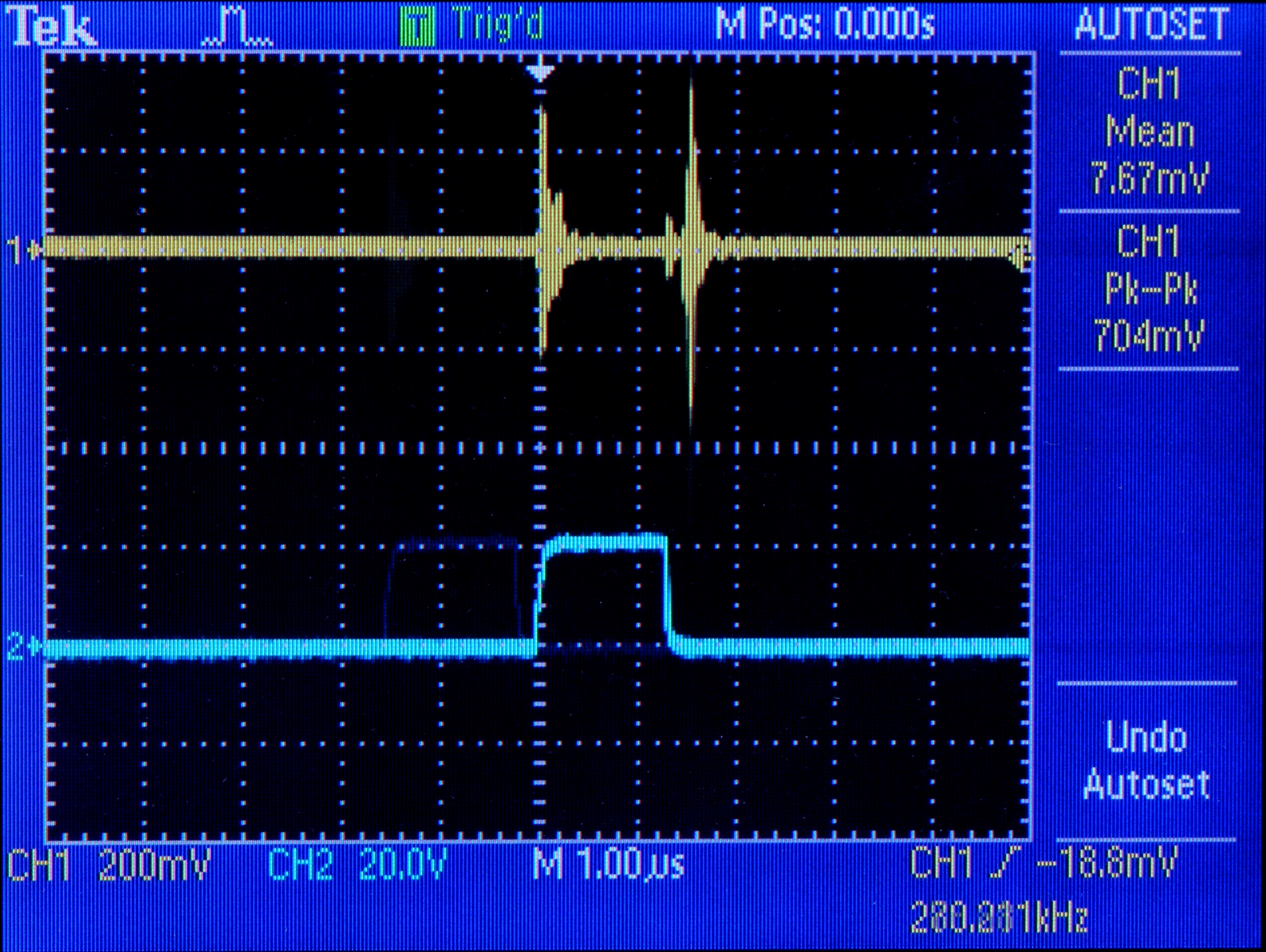
Trace 2 is the FET gate drive; trace 1 is noise on the ground plane. There’s almost a volt of spike on the ground plane every time the FET switches on and off. I hadn’t been seeing noise everywhere else throughout the circuit; I’d been seeing noise as measured between each point and noisy ground.
(Okay, how can a scope register a signal between its probe and its ground when they’re connected to the same point? I assume its ground connection is capacitor-filtered and its probe obviously is not. That could mean that I wasn’t just seeing dirty ground everywhere and there really is noise throughout the circuit — but I know there shouldn’t be that kind of noise on the ground plane, and I want to eliminate that before worrying too hard about the rest.)
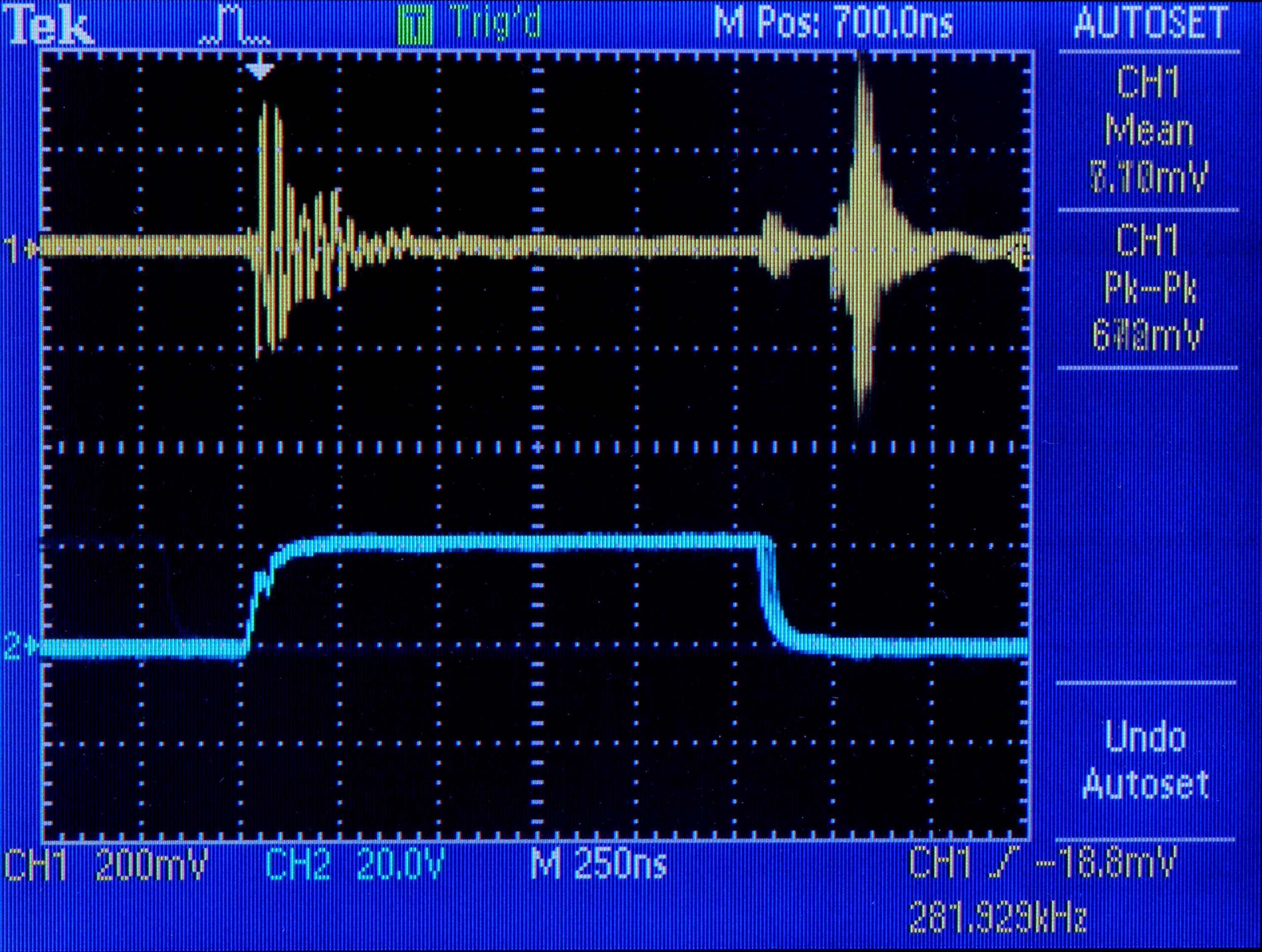
Here’s the same thing zoomed in,
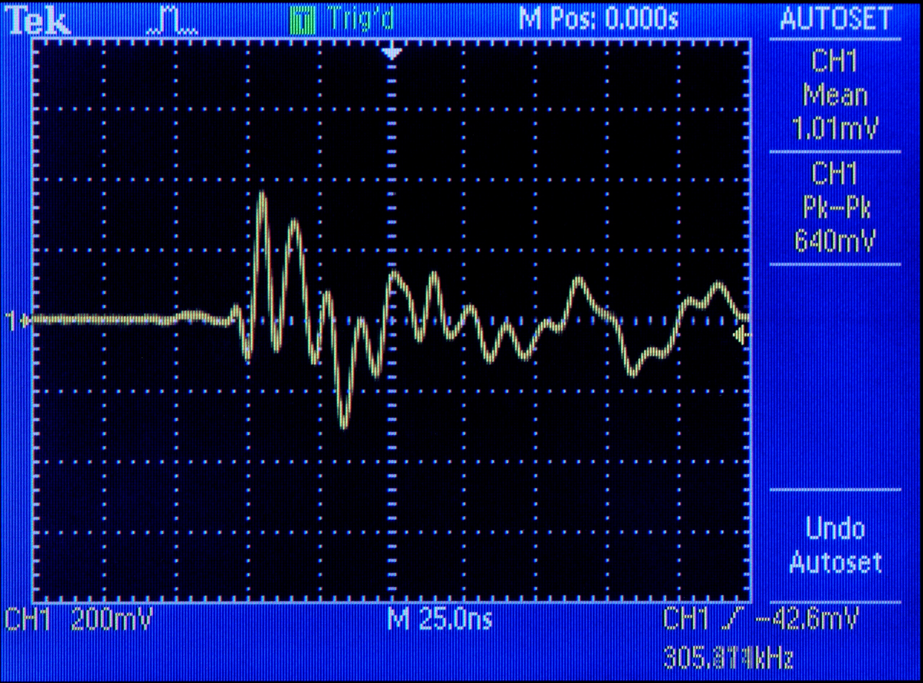
and a closeup of just the first ringing.
To add insult to injury, the only connection between the primary and secondary sides of the circuit besides the transformer is C24, which capacitively couples the two ground planes. (I don’t fully understand why.) And C24 couples the noise into the secondary side’s ground slick as can be, where it appears on the power going to the mixer. Crap.
My immediate intuition was that the big 100uF 400V capacitor across the power supply was aging and no longer able to respond to transients as fast as 10MHz. When the FET switches on, the circuit makes almost a dead short between +170V and ground through the transformer; it seems natural that ringing during the transistions should appear on both the power and ground lines, and C18 is the only thing that would really be in a position to catch it.
It also occurred to me that maybe this ringing has been there from day one, and either the engineers didn’t notice or didn’t care. But that’s not a happy thought; and as I don’t have access to an identical mixer to see how it operates, I’ll just push that back to the dark, cynical recesses of my mind.
C18 has a lot of capacitance; but it’s so big, it might not be able to respond quickly enough to very fast spikes. This, I assume, is why C2 is paralled with C1 — so perhaps a smaller-valued capacitor in parallel with C18 would help kill the 10MHz ringing. (Perhaps a brand new replacement for C18 would do the job also — but if that fixed it, then in a few years the new capacitor would have aged enough to regain the same problem. Better to fix by design than by manufacturing.)
I found a 330nF capacitor that looked like I could trust it with 170V plus spikes and soldered it on in parallel with C18, and it doesn’t appear to have made any difference. Also tried 4.7nF, 150pF, and 47pF (shown here), all with no apparent change to the ringing.
I don’t have many ideas left, and I’m really not happy leaving the power supply the way it is. Maybe someone out there with more design or repair experience has a suggestion? Maybe the scope is playing tricks on me and someone can explain how?
Oh, and this…
https://www.reelaudio.co.uk/Soundcraft_S_S2006APSU.shtml
Hello,
I also had a Soundcraft mixer with a bad power supply.
In my case the 100 V. zener and a diode for the 48 V had failed.
Just like your power supply, the center of the PCB looked like it had often been heated to a high temperature, but all components still looked ‘like new’, anyway not overheated!
What could cause this coloration of the PCB? (No high power parts there!)
Your schematic has been a great help in repairing this power supply, thanks!
Best regards,
Ruud van Steenis.
Hello, i want to give you a big thanks ! your investigation helps me a lot to understand and to repair a soundcraft mixer now… in 2021 !
Now i want to know the value of the R40 resistor which is burnt, just above the three op amps in the main board.
Anybody does have a schematic or a open mixer ?
thanks in advance
Saludos cordiales desde Carora Lara Venezuela.
Hello man.
Please send me your manual soundcraft EPM 8 or 12, mixer PDF.
The Power supply original no working.
Agradecido de antemano por su atención.
Ing. Miguel González