I finished assembling my CupCake a week and a half ago — more detail in a separate post. For now, information about my decision to use mouse cables to wire up the endstops.
The CupCake comes with CAT5E (ethernet, among other things) patch cords to use to connect everything together. The X stage doesn’t have room for 8P8C (RJ-45) connectors on the Y-axis endstops, so you have to butcher the cables and put one new end on each. Ethernet patch cords are pretty bulky and unsupple; and I figured since I had to terminate my own cables anyway, I might as well use something more to my liking. I don’t fault MakerBot for supplying patch cords — it’s a great choice for most makers, and weirdos like me can always roll their own.
I only needed three conductors and headphone cable is pretty supple; but the very fine stranded wires inside headphone cable can be a bit of a challenge to work with. Cords from dead mice seemed like a better fit, even though they have an extra conductor I didn’t need. So I grabbed some from the “Keith box” at the office and got to work.
Mouse Guts

For those who haven’t seen it before, here’s the inside of an optical mouse.

The left end of the scrolly wheel axle has an encoder; the right end sits on top of a microswitch (for clicking the wheel button).

The LED shines into the prism, is reflected onto the desk (or whatever) and back up into the IC, and picked up by the low-res CCD.
I snipped off the cable inside the case and closed Mr. Mousy back up for another salvaging visit.
CupCake Y Endstop Cables
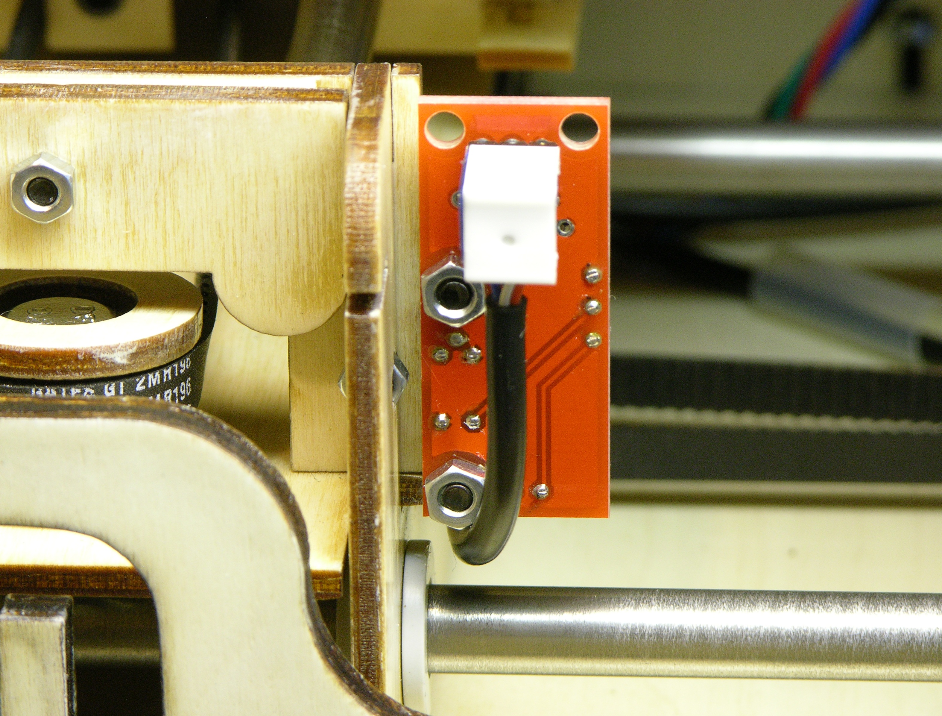
I plan ultimately to replace all of the ethernet patch cords with cut-to-length, slim, supple mouse cords; but for now I’ve just done the Y axis endstops. The three conductors press into insulation displacement connectors on the three-pin .1″-spacing header.
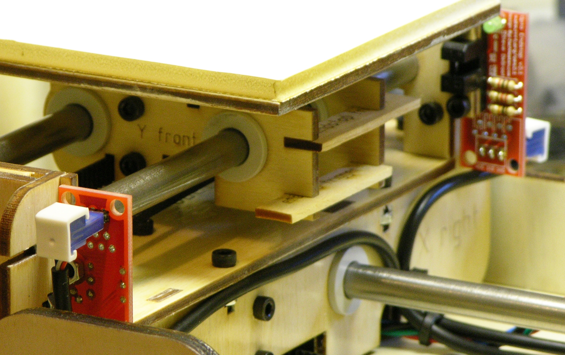
The two endstop cables are temporarily held in place with hot glue and are zip-tied to the stepper motor cabling.
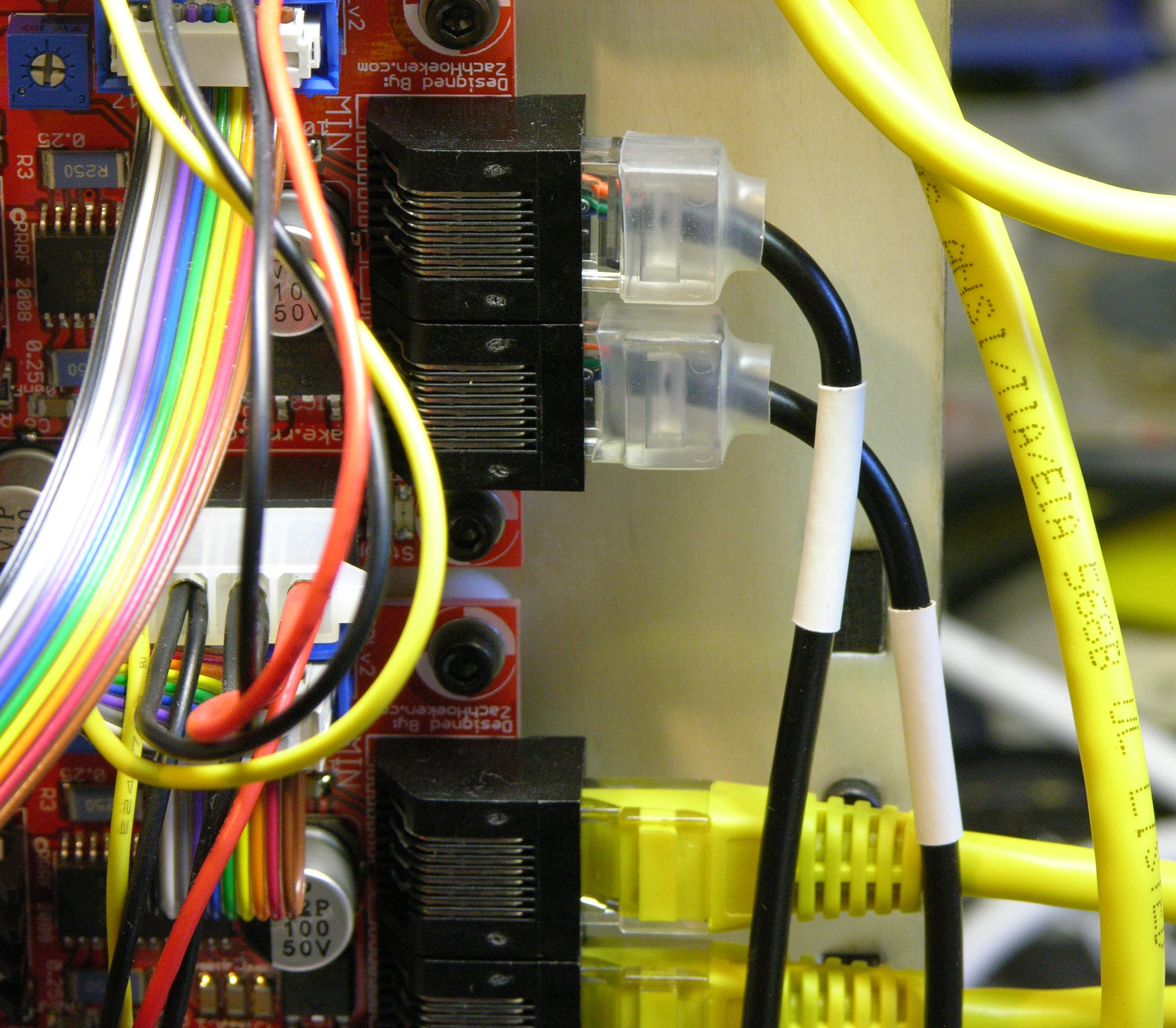
At the PCB end, I crimped on RJ-45 connectors and heatshrinked a “boot” over the locking tab for snagless cable-pulling. (It’s a bit of a trick to pry the tab back out just enough while the heatshrink is soft without burning yourself because it’s still hot.)
Prior to crimping, I heatshrinked a white band around each cable on which to write “Y max” and “Y min” after I know which is which, and I slipped more clear heatshrink (not shown) around the cable to shrink around the labeled white band to protect the writing.
About That Y Max and Min …
Right now X- stepper commands move the CupCake build stage to the right, placing the extruder above the left end of the stage. This seems correct to me. But Y- stepper commands move the stage forward so the extruder is above the back of the stage. That is, (Xmin, Ymin) is at the back left of the build stage, making the CupCake run on a left-handed coordinate system. Aaaargh!!!
Happily, the CupCake firmware has settings to mirror axes. But the Y axis appears to be mirrored somewhere else already — I’ve printed a model drawn in Art of Illusion (definitely right-handed) that was asymmetric in the Y axis and it came out correct. So I don’t know where the other Y flip is happening; and even if I should flip the Y axis in firmware, I don’t know whether or not that will flip the meaning of the min and max endstops. So meanwhile, I figure I better not label them yet.
Nice. Would you mind publishing a wiring diagram showing the endstop connector and the RJ45?
Regards,
tamberg
Keith,
This is great, much better in many ways than the ethernet cables (size, flexibility etc). I’d like to duplicate it, but am unsure about how to figure out wire placement at either end – could you explain this when you get a chance.
Thanks!
Kevin, I wouldn’t mind doing that but it’s not quite that simple. I suspect that not all mouse cables have the same colors (strike one); but more importantly, I wired the two cables differently, as one endstop mounts upside-down from the other but both cables are installed pointing down.
I could double-check my cables for the details, but I know that what I did is look at the pinouts for the connectors on both ends and come up with a pinning that would put the right wires through to the right places (duh!). I always hate doing that because of how long it takes me to be sure that I’m looking at the plug versus the jack and the top versus the bottom, but apparently I got it right because they work.
Maybe I just need to provide pinouts for the pair of endstops.